Sign In
Upload
Manuals
Brands
Kontron Manuals
Computer Hardware
cPCI-MXS64
Kontron cPCI-MXS64 Manuals
Manuals and User Guides for Kontron cPCI-MXS64. We have
2
Kontron cPCI-MXS64 manuals available for free PDF download: Technical Reference Manual
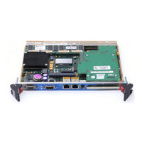
Kontron cPCI-MXS64 Technical Reference Manual (134 pages)
6U CompactPCI 64-bit System Processor
Brand:
Kontron
| Category:
Computer Hardware
| Size: 4.82 MB
Table of Contents
Table of Contents
10
Product Description
17
Product Overview
18
Product Specifications
19
Hot Swap Capability
21
Interfacing with the Environment
23
Cpci
23
Mezzanine
23
Compatibility with Other KONTRON Products
24
Mezzanine Card Concept
25
Kontron's Mezzanine Concept
26
PMC Concept
26
Compactflash Feature
26
Onboard Features
27
Compactflash Interface
28
Setups
28
Enhanced IDE Interfaces
29
Ethernet Interfaces
30
Front Plate Configuration
30
Cpci I/O Configuration
30
Floppy Disk Interface
31
PS/2 Keyboard / PS/2 Mouse Interface
31
Parallel Port
32
Standard Mode
33
EPP Mode
33
ECP Mode
33
Power Management
34
SCSI Interface
34
Serial Ports
35
Serial Port 1
35
Remote Reset
35
Front Plate Configuration
36
Serial Port 2
36
Serial Port 3
37
Infrared Mode
38
Protocol
38
Serial Port 4
39
Thermal Management
39
USB Interfaces
40
Video Interface
41
Supported Resolutions
41
Major Features Description
42
Installing the Board
43
Setting Jumpers
44
Jumper Description for the CPCI-MXS64
44
PCI-MXS64 - Jumper Settings
45
Register's Description RS232/RS485
46
History and Monitor Status
46
Multimedia, History Status
47
Monitoring Status and I/O Access
47
Uart 3 Pnp Configuration
47
Uart 4 Pnp Configuration
48
Digital Watchdog
48
NMI Control
49
0Register Bits Description (Summary)
50
Onboard Interconnectivity
51
Cpci-MXS64 Block Diagram
51
North Bridge Chipset
52
21154 PCI-To-PCI Bridge
53
82371AB PCI-To-ISA Bridge / IDE Xcelerator (PIIX4)
53
Onboard Connectors and Headers
54
Front Plate Connectors and Indicators
55
Faceplate Options
56
Compactpci Connectors
57
Customizing the Board
58
Processor and Fan
58
Backup Battery
59
Memory
60
SDRAM System Memory
60
DIMM Installation
61
Supervision Features
62
Power Fail Monitoring
62
Watchdog
63
Thermal Management
65
Building a Cpci System
66
Backplane
67
Rear-Panel I/O
68
Storage Devices
70
Power Supply
70
Fan Tray
70
Installing the Board into a Bay
70
Connector Keying
71
Bus Mastering
71
Connection
71
Cpci I/O Signals
72
J3 Signal Specification
72
Ethernet Leds
72
Ethernet 1
72
Serial Port 3
73
Serial Port 4
73
IDE LED Signals
73
IR Serial Port 2
73
Hot Swap HA (High Availability) Signals
74
Miscellaneous Signals
74
J4 Signal Specification
74
Power Management
74
SCSI Interface
75
Video Interface
75
Ethernet 1 Interface
76
Hot Swap HA (High Availability) Signals
76
IDE 1 Interface
76
J5 Signal Specification
77
IDE 0 Interface
77
USB 0 and 1 Interfaces
77
Floppy Disk Interface
78
Serial Port 2
78
Serial Port 1
78
Parallel Port
79
Miscellaneous Signals
79
Keyboard Interface
79
Mouse Interface
79
Software Setups
80
BIOS Setup Program
81
Accessing the BIOS Setup Program
81
Main Menu
83
Setups
84
Standard CMOS Setups
85
Saving & Exiting Operations
85
BIOS Features Setup
86
Chipset Features Setup
88
Power Management Setup
90
Pnp/Pci Configuration
92
Cpu/Board Features Setup
93
Integrated Peripherals
94
Bios Update & Emergency Procedure
95
VT100 Mode
96
Requirements
96
Setup & Configuration
96
Running Without a Terminal
97
Board Specifications
99
MEMORY & I/O MAPS Memory Mapping
103
I/O Mapping
104
Interrupt Lines
105
IRQ Lines
105
DMA Channels
105
Board Diagrams
106
Top Devices Surface Mount
106
Assembly Bottom Diagram
107
Mounting Holes
108
Connector Holes
109
Connector Pinouts
110
Cpci-MXS64 Connectors and Headers
110
J1 CPCI Bus
111
J2 CPCI Bus
112
J3 CPCI Bus
113
J4 CPCI Bus
114
J5 CPCI Bus
115
J12, Video (VGA
115
J13, Serial Port 1
116
J14, Mezzanine PCI
116
J15/J16, Ethernet 1 and 2
117
J17, PS/2 Keyboard/Mouse
117
J18, Compactflash Disk
117
J19, Storage Mezzanine
118
J20, Pmc
119
J21, Pmc
120
Hot Swap Switch
121
S1 - Reset Switch
121
BT1, CMOS Battery Backup Connector
121
Bios Setup Error Codes
122
POST Beep
122
POST Messages
122
Error Messages
123
POST Codes
124
Emergency Procedure
129
How to Run Emergency Procedure
129
Generate an Emergency Floppy Diskette
130
Getting Help
131
Advertisement
Kontron cPCI-MXS64 Technical Reference Manual (132 pages)
6U CompactPCI 64-bit System Processor
Brand:
Kontron
| Category:
Computer Hardware
| Size: 1.85 MB
Table of Contents
Table of Contents
9
Product Description
16
Product Overview
16
Product Specifications
18
Hot Swap Capability
20
Interfacing with the Environment
22
Cpci
22
Mezzanine
22
Compatibility with Other KONTRON Products
23
Mezzanine Card Concept
24
Kontron's Mezzanine Concept
25
PMC Concept
25
Compactflash Feature
25
Onboard Features
26
Compactflash Interface
26
Setups
27
Enhanced IDE Interfaces
28
Ethernet Interfaces
29
Front Plate Configuration
29
Cpci I/O Configuration
29
Floppy Disk Interface
30
PS/2 Keyboard / PS/2 Mouse Interface
30
Parallel Port
31
Standard Mode
32
EPP Mode
32
ECP Mode
32
Power Management
33
SCSI Interface
33
Serial Ports
34
Serial Port 1
34
Remote Reset
34
Front Plate Configuration
35
Serial Port 2
35
Serial Port 3
36
Infrared Mode
37
Protocol
37
Serial Port 4
38
Thermal Management
38
USB Interfaces
39
Video Interface
40
Supported Resolutions
40
Major Features Description
41
Installing the Board
42
Setting Jumpers
43
Jumper Description for the CPCI-MXS64
43
CPCI-MXS64 - Jumper Settings
44
Register's Description RS232/RS485
45
History and Monitor Status
45
Multimedia, History Status
46
Monitoring Status and I/O Access
46
Uart 3 Pnp Configuration
46
Uart 4 Pnp Configuration
47
Digital Watchdog
47
NMI Control
48
0Register Bits Description (Summary)
49
Onboard Interconnectivity
50
Cpci-MXS64 Block Diagram
50
Mobile Pentium ® II / III Processor
51
North Bridge Chipset
51
21154 PCI-To-PCI Bridge
52
82371AB PCI-To-ISA Bridge / IDE Xcelerator (PIIX4)
52
Onboard Connectors and Headers
53
Front Plate Connectors and Indicators
54
Faceplate Options
55
Compactpci Connectors
56
Customizing the Board
57
Processor and Fan
57
Backup Battery
58
Memory
59
SDRAM System Memory
59
DIMM Installation
60
Supervision Features
61
Power Fail Monitoring
61
Watchdog
62
Thermal Management
64
Building a Cpci System
65
Backplane
66
Rear-Panel I/O
67
Storage Devices
69
Power Supply
69
Fan Tray
69
Installing the Board into a Bay
69
Connector Keying
70
Bus Mastering
70
Connection
70
Cpci I/O Signals
71
J3 Signal Specification
71
Ethernet Leds
71
Ethernet 1
71
Serial Port 3
72
Serial Port 4
72
IDE LED Signals
72
IR Serial Port 2
72
Hot Swap HA (High Availability) Signals
73
Miscellaneous Signals
73
J4 Signal Specification
73
Power Management
73
SCSI Interface
74
Video Interface
74
Ethernet 1 Interface
75
Hot Swap HA (High Availability) Signals
75
IDE 1 Interface
75
J5 Signal Specification
76
IDE 0 Interface
76
USB 0 and 1 Interfaces
76
Floppy Disk Interface
77
Serial Port 2
77
Serial Port 1
77
Parallel Port
78
Miscellaneous Signals
78
Keyboard Interface
78
Mouse Interface
78
Software Setups
79
BIOS Setup Program
80
Accessing the BIOS Setup Program
80
Main Menu
82
Setups
83
Standard CMOS Setups
84
Saving & Exiting Operations
84
BIOS Features Setup
85
Chipset Features Setup
87
Power Management Setup
89
Pnp/Pci Configuration
91
Cpu/Board Features Setup
92
Integrated Peripherals
93
Bios Update & Emergency Procedure
94
VT100 Mode
95
Requirements
95
Setup & Configuration
95
Running Without a Terminal
96
Board Specifications
98
MEMORY & I/O MAPS Memory Mapping
102
I/O Mapping
103
Interrupt Lines
104
IRQ Lines
104
DMA Channels
104
Board Diagrams
105
Top Devices Surface Mount
105
Assembly Bottom Diagram
106
Mounting Holes
107
Connector Holes
108
Connector Pinouts
109
Cpci-MXS64 Connectors and Headers
109
J1 CPCI Bus
110
J2 CPCI Bus
111
J3 CPCI Bus
112
J4 CPCI Bus
113
J5 CPCI Bus
114
J13, Serial Port 1
115
J14, Mezzanine PCI
115
J15/J16, Ethernet 1 and 2
116
J17, PS/2 Keyboard/Mouse
116
J18, Compactflash Disk
116
J19, Storage Mezzanine
117
Hot Swap Switch
120
S1 - Reset Switch
120
Bios Setup Error Codes
121
POST Beep
121
POST Messages
121
Error Messages
122
POST Codes
123
Emergency Procedure
128
How to Run Emergency Procedure
128
Generate an Emergency Floppy Diskette
129
Getting Help
130
Advertisement
Related Products
Kontron cPCI-MXS64GX
Kontron cPCI-DMXS64GX
Kontron CPCI-MXS
Kontron CP308
Kontron CP3002-RA
Kontron CP6005-SA
Kontron CP3003-SA
Kontron CP3003-V
Kontron CP-ADAP-P47-PB (3U)
Kontron CP3-BP6-ATX
Kontron Categories
Computer Hardware
Motherboard
Server
Desktop
PCI Card
More Kontron Manuals
Login
Sign In
OR
Sign in with Facebook
Sign in with Google
Upload manual
Upload from disk
Upload from URL