Sign In
Upload
Manuals
Brands
Kollmorgen Manuals
Amplifier
S74802-NAF2NA
Kollmorgen S74802-NAF2NA Manuals
Manuals and User Guides for Kollmorgen S74802-NAF2NA. We have
1
Kollmorgen S74802-NAF2NA manual available for free PDF download: Instruction Manual
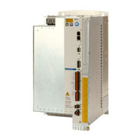
Kollmorgen S74802-NAF2NA Instruction Manual (166 pages)
Digital Servo Amplifier STO dual channel
Brand:
Kollmorgen
| Category:
Amplifier
| Size: 21.23 MB
Table of Contents
Table of Contents
3
1 Table of Contents
9
2 General
9
About this Manual
9
Using the PDF Format
9
Symbols Used
10
Standards Used
11
Abbreviations Used
12
3 Safety
13
You Should Pay Attention to this
13
Warning Notes Placed on the Product
15
Use as Directed
16
Prohibited Use
17
4 Product Life Cycle Handling
18
Transport
18
Packaging
18
Storage
18
Decommissioning
18
Maintenance and Cleaning
19
Disassembly
19
System Repair
20
Disposal
20
5 Approvals
21
Conformance with UL
21
CE Conformance
22
European Directives and Standards for the Machine Builder
22
Functional Safety Conformance According to EC Machinery Directive
23
Conformance with Rohs
23
Conformance with REACH
23
Conformance with EAC
24
6 Package
25
Package Supplied
25
Nameplate
25
Part Number Scheme
26
7 Technical Description
27
The S700 Family of Digital Servo Amplifiers
27
Technical Data
30
Rated Data
30
Inputs, Outputs, Aux. Voltage Supply
31
Connectors
31
Recommended Tightening Torques
31
Fusing
32
Ambient Conditions, Ventilation, and Mounting Position
32
Conductor Cross-Sections
33
Motor Holding Brake
34
LED Display
35
Grounding System
35
Dynamic Braking (Brake Circuit)
35
Switch-On and Switch-Off Behavior
36
Behavior in Standard Operation
37
Behavior in the Event of an Error (with Standard Setting)
38
Stop-, Emergency Stop-, Emergency off Function to IEC 60204
39
Stop
39
Emergency Stop
40
Emergency off
40
Safety Function STO
41
Safety Characteristic Data
41
Safety Notes
42
Use as Directed
43
Prohibited Use STO
43
Enclosure
43
Wiring
43
Technical Data
43
Pinout
44
Functional Description
45
Safe Operation Sequence
46
Control Circuit Single Channel Sil2/Pld (Example)
47
Control Circuit Dual Channel Sil2/Pld (Example)
48
Control Circuit Dual Channel Sil3/Ple (Example)
49
Mains Supply Circuit (Example)
50
Functional Test
50
Single or Dual Channel Control, SIL CL2 / Pld
50
SIL CL3 / Ple Dual Channel Control
51
Shock-Hazard Protection
52
Leakage Current
52
Residual Current Protective Device (RCD)
52
Isolating Transformers
52
8 Mechanical Installation
53
Important Notes
53
Guide to Mechanical Installation
53
Dimensions
54
Device with Heat Sink
54
Device with Coldplate
55
Assembly
56
Mounting the Shielding Plate
56
Backplane Mounting - Devices with Heat Sink
57
Backplane Mounting - Devices with Coldplate
58
9 Electrical Installation
59
Important Notes
59
Guide to Electrical Installation
60
Wiring
61
Shielding Connection to the Front Panel
62
Technical Data for Connecting Cables
63
Components of a Servo System
64
Block Diagram
65
Connector Assignments
66
Connection Diagram (Overview)
67
Voltage Supply
68
Connection to Various Mains Supply Networks
68
Mains Supply Connection (X0)
69
Auxiliary Supply (X4)
69
DC Bus Link (X8)
70
DC Bus Topology
71
External Brake Resistor (X8)
71
Capacitor Module KCM (X8)
72
Motor Connection
73
Motor Power Connection (X8)
73
Kollmorgen | Kdn.kollmorgen.com | July
73
Motor Holding Brake Connection (X8, X9)
74
Feedback Systems
74
Primary and Secondary Feedback Types
75
SFD3 (X1), Single Cable Connection
76
HIPERFACE DSL (X1), Single Cable Connection
77
Resolver (X2)
78
Sine Encoder with Biss Analog (X1)
79
Encoder with Biss Digital (X1)
80
Sine Encoder with Endat 2.1 (X1)
81
Encoder with Endat 2.2 (X1)
82
Sine Encoder with HIPERFACE (X1)
83
Sine Encoder with SSI (X1)
84
Sine Encoder Without Data Channel (X1)
85
Sine Encoder with Hall (X1)
86
ROD (Aquadb) 5V, 1.5Mhz (X1)
87
ROD (Aquadb) 5V, 350Khz (X1)
88
ROD (Aquadb) 5V, 350Khz with Hall (X1)
89
ROD (Aquadb) 24V (X3)
90
ROD (Aquadb) 24V with Hall (X3, X1)
91
SSI Absolute Encoder (X1)
92
Hall Sensors (X1)
93
Electronic Gearing, Master-Slave Operation
94
Encoder Control Types
94
Connection to Stepper Motor Controllers (Step and Direction)
95
Step / Direction with 24 V Signal Level (X3)
95
Step / Direction with 5 V Signal Level (X1)
95
Master-Slave Operation
96
Connection to an S700 Master, 5V Signal Level (X1)
96
Connection to an S700 Master, 5V Signal Level (X5)
96
Encoder Emulation, Position Output
97
Incremental Encoder Output - a Quad B (X1)
97
SSI Encoder Output (X1)
98
Digital and Analog Inputs and Outputs
99
Analog Inputs (X3B)
99
Digital Inputs (X3A, X3B, X4)
100
Connector X3A, X3B
100
Connector X4
101
Digital Outputs (X3A, X3B, X4)
102
Connector X4
103
Connectors X3A, X3B
103
RS232 Interface, PC Connection (X6)
104
CAN-Bus Interface (X6)
105
Ethernet Interface (X7)
106
Memory Card
107
10 Setup
108
Important Notes
108
Setup Software
109
Use as Directed
109
Software Description
109
Hardware Requirements, Operating Systems
110
Installation under WINDOWS
110
Quickstart, Initial Drive Test
111
Preparation
111
Connect
113
Important Screen Elements
114
Setup Wizard
115
Basic Setup
115
Units/Mechanical
116
Motor (Linear) / Feedback (Encoder)
117
Motor (Rotary) and Feedback
117
Save Parameters and Restart
118
Motion Service (Jog Mode)
118
More Setup Screens
119
Multi Axis System
120
Keypad Operation and LED Display
120
Operation
121
Status Display
121
Standard Menu Structure
121
Advanced Menu Structure
122
Error Messages
123
Warning Messages
124
Trouble Shooting
125
11 Expansions
126
Expansion Cards for Slot
126
Guide to Installation of Expansion Cards in Slot
126
Expansion Card -I/O-14/08
127
Entering a Motion Block Number (Example)
127
Leds
127
Technical Data
127
Connector Assignments
128
Connection Diagram (Default)
129
Expansion Card -PROFIBUS
130
Connection Diagram
130
Connection Technology
130
Expansion Card -SERCOS
131
Connection Technology
131
Leds
131
Connection Diagram
132
Setup
132
Expansion Card - DEVICENET
133
Connection Technology, Connection Diagram
133
Combined Module Status and Network Status LED
134
Setup
134
Bus Cable
135
Expansion Card -SYNQNET
136
NODE ID Switch
136
NODE LED Table
136
Synqnet Connection, Connector X21B / X21C (RJ-45)
136
Connection Diagram Digital Inputs and Outputs, Connector X21A
137
Digital Inputs and Outputs, Connector X21A (Subd 15-Pin, Socket)
137
Expansion Card - FB-2To1
138
Pinout
138
Wiring Example with Biss Digital (Primary) and Sincos (Secondary)
139
Expansion Module -2CAN
140
Connection Technology
140
Installation
140
Kollmorgen | Kdn.kollmorgen.com | July
141
Expansion Cards for Slot 2
142
Expansion Cards "Posi/O" & "Posi/O-Monitor
143
Feedback
144
ROD (Aquadb) 5V with Hall (X5, X1)
145
SSI Encoder (X5, X1)
146
Sine Encoder with SSI (X5, X1)
147
Electronic Gearing, Master-Slave Operation (X5)
148
Encoder-Emulation (X5)
149
SSI Encoder Output (X5)
150
Analoge Inputs and Outputs
151
Expansion Cards for Slot 3
152
Expansion Card "Safety 2-2" (S4)
153
Wiring Supply Voltage 24 V for Digital Outputs
154
Expansion Card "Safety 1-2" (S3)
155
External Encoder S1-2
156
12 Appendix
157
Order Codes
159
Expansion Cards
160
13 Index
161
14 Record of Document Revisions
165
Advertisement
Advertisement
Related Products
Kollmorgen S74802-NANAF2
Kollmorgen S74802
Kollmorgen S74802-NANANA
Kollmorgen S7010
Kollmorgen S70101-NANANA
Kollmorgen S70301-NAF2NA
Kollmorgen S70301-NANAF2
Kollmorgen S70601-SE
Kollmorgen S70101-NANAF2
Kollmorgen S7120P-NAF2NA
Kollmorgen Categories
Servo Drives
Amplifier
Touch terminals
DC Drives
Engine
More Kollmorgen Manuals
Login
Sign In
OR
Sign in with Facebook
Sign in with Google
Upload manual
Upload from disk
Upload from URL