Sign In
Upload
Manuals
Brands
Keithley Manuals
Switch
3700 series
Keithley 3700 series Manuals
Manuals and User Guides for Keithley 3700 series. We have
5
Keithley 3700 series manuals available for free PDF download: Reference Manual, User Manual, Installation Instructions Manual
Keithley 3700 series Reference Manual (657 pages)
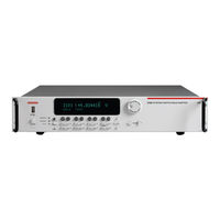
System Switch/Multimeter
Brand:
Keithley
| Category:
Test Equipment
| Size: 7 MB
Table of Contents
Limitation of Warranty
3
Safety Precautions
7
Table of Contents
9
Contact Information
23
Overview
23
In this Section
23
Introduction
23
Measure and Switching Capabilities
24
Warranty Information
24
Figure 1-1: DMM Measurement Capabilities
24
Displaying the Unit's Serial Number
25
TSP Programming Fundamentals
27
Introduction
27
Test Script Processor (TSPTM)
28
Run-Time Environment
29
Queries
29
Scripts
30
Named Scripts
31
Programming Overview
32
Chunk Defined
32
Script Defined
33
Figure 2-1: TSP Test Script Example
33
Run-Time Environment
34
Nonvolatile Memory
34
TSPTM Programming Levels
34
Programming Model for Scripts
35
Figure 2-2: Programming Model for Scripts
35
Installing the TSPTM Software
36
System Connections
36
Rear Panel Summary
36
Figure 2-3: Rear Panel Features
36
GPIB Interface Connection
37
Figure 2-4: GPIB Cable
37
GPIB Address
38
Standard RJ-45 (Ethernet) Interface Connection
38
USB Connection
39
Using Test Script Builder (TSB)
39
Project Navigator
40
Script Editor
40
Figure 2-5: Using Test Script Builder (TSB)
40
Programming Interaction
41
Sending Commands and Statements
41
Measure Voltage
41
Read and Write to the Digital I/O Port
42
Display User-Defined Messages
42
User Scripts
42
Script Examples
43
Creating a User Script
46
Saving a User Script
48
Loading a User Script
50
Running a User Script
51
Loading a Script from the Series 3700 Front Panel
54
Saving a Script from the Series 3700 Front Panel
55
Modifying a User Script
55
Script Management
56
Differences: Remote Versus Local State
58
Remote State
58
Local State
58
TSP-Linktm System
58
Stand-Alone System
59
Test Script Language (TSL) Reference
59
Introduction
59
Variables and Types
60
Operators
60
Functions
61
Tables/Arrays
62
Precedence
63
Logical Operators
64
Concatenation
65
Branching
66
Loop Control
67
Standard Libraries
68
Base Library Functions
69
String Library Functions
70
Math Library Functions
71
Introduction
73
In this Section
73
TSP Advanced Features
73
Figure 3-1: Multiple TSP-Link Networks
74
Figure 3-2: Single TSP-Link Network with Groups
75
Using Groups to Manage Nodes on TSP-Linktm Network
76
Master Node Overview
77
Group Leader Overview
77
Assigning Groups
77
Reassigning Groups
78
Running Parallel Test Scripts
78
Coordinating Overlapped Operations in Remote Groups
79
Using the Data Queue for Real-Time Communication
80
Copying Test Scripts Across the TSP-Linktm Network
80
Removing Stale Values from the Reading Buffer
81
Commands Related to TSP Advanced Features
82
Using the Front Panel
89
In this Section
89
Front Panel Introduction
89
Figure 4-1: Model 3706 System Switch/Multimeter
90
Figure 4-2: Model 3706-S System Switch (no DMM)
90
Figure 4-3: Model 3706-NFP System Switch/Multimeter
91
Figure 4-4: Model 3706-SNFP System Switch (no DMM)
91
Display
92
Figure 4-5: Active Channel Display Example
93
Figure 4-6: MAIN MENU Display
95
Channel Type Indication
96
Using the Front Panel with Non-Switch Channels
97
Special Keys and Power Switch
99
CONFIG Key
99
CONFIG CHAN Key
99
DISPLAY Key
104
POWER Switch
105
RESET Switch
105
Operation Keys
105
CHAN Key
105
DELETE Key
108
DMM Key
109
ENTER Key
113
EXIT Key
113
FILTER Key
113
Function Key
114
INSERT Key
114
LIMIT Key
115
LOAD Key
115
MENU Key
116
PATT Key
117
REL Key
118
RUN Key
118
SCAN Key
119
SLOT Key
120
TRIG Key
120
Range Keys, Cursor Keys, and Navigation Wheel
120
AUTO Key
120
CURSOR Keys
120
Navigation Wheel
121
RANGE Keys
121
Action Keys
121
CLOSE Key
121
OPEN ALL Key
121
OPEN Key
122
RATE Key
122
Recall Key
122
STEP Key
122
STORE Key
123
Range
125
Measurement Ranges and Maximum Readings
125
Range, Digits, Rate, Bandwidth, and Filter
125
In this Section
125
Manual Range Keys
126
Auto Ranging over the Front Panel
127
Scanning
127
Range Remote Programming (ICL)
127
Digits ICL Programming
128
Scanning
128
Setting Digits
128
Rate
129
Figure 5-1: Speed Versus Noise Characteristics
129
Setting Rate from the Front Panel
131
Setting Measurement Speed from a Remote Interface
131
Bandwidth
131
Filter
132
Filter Characteristics
132
Figure 5-2: Moving Average Filter
133
Figure 5-3: Repeating Average Filter
133
Digital Filter Window
134
Figure 5-4: Filter Window
135
Relative, Math, and Db
137
Relative
137
Basic Front Panel REL Procedure
138
REL Remote Operation
138
Scanning
139
Math Calculations
139
MX+B
140
Percent
142
Reciprocal (1/X)
143
Db Commands
146
Db Configuration
146
Db Scanning
147
Buffer: Data Storage and Retrieval
149
Buffer Overview
149
Front Panel Operation
150
Creating and Selecting a Reading Buffer
150
Selecting a Reading Buffer
151
Storing Readings
151
Saving Readings
151
Clearing Readings
152
Deleting a Reading Buffer
153
Recalling Readings
153
Time Stamp
153
Channel Display
154
Buffer Configuration (Front Panel)
154
Appending Readings
155
Remote Buffer Operation
155
Data Store (Buffer) Commands
156
Reading Buffers
160
Buffer Read-Only Attributes
161
Time and Date Values
164
Buffer Status
164
Dynamically-Allocated Buffers
165
Dynamic Buffer Programming Example
166
Exceeding Reading Buffer Capacity
169
In this Section
173
Scanning Fundamentals
173
Scanning
173
Channel Assignments
174
Events
174
Figure 8-1: Event Detector
174
Event Blenders
175
Foreground and Background Scan Execution
175
Trigger Model
176
Figure 8-2: Trigger Model
176
Trigger Model Components
177
Scan and Step Counts
179
Basic Scan Procedure
179
Buffer
181
Changing Channel and DMM Attributes of an Existing Scan
181
Front Panel Scanning
182
Scan Configuration
183
Bus Operation Scanning
184
ICL Commands
184
Scanning Examples
186
Hardware Trigger Modes
190
Set each Channel so It Closes with a Digio 1 Event Trigger. Scan.trigger.channel.stimulus = Digio.trigger[1].Event_Id
190
Scan.bypass = Scan.off
190
Create Scan for Channels 1 to 60 on the Card Installed
190
In Slot 3
190
Scan.create('3001:3060', 'Mydcv')
190
Initiate the Scan to Execute in the Background and Save
190
Readings to a Buffer Called "Mybuffer
190
Scan.background(Mybuffer)
190
Digio.trigger[1].Mode = Digio.trig_Falling
190
Falling Edge Trigger Mode
192
Figure 8-3: Falling Edge Input Trigger
192
Figure 8-4: Falling Edge Output Trigger
192
Rising Edge Master Trigger Mode (Version 1.4.0 or Higher)
193
Figure 8-5: Risingm Output Trigger
193
Rising Edge Acceptor Trigger Mode (Version 1.4.0 or Higher)
194
Figure 8-6: Risinga Input Trigger
194
Figure 8-7: Risinga Output Trigger
194
Either Edge Trigger Mode
195
Figure 8-8: Either Edge Input Trigger
195
Understanding Synchronous Triggering Modes
196
Figure 8-9: Either Edge Output Trigger
196
Figure 8-10: Synchronousm Input Trigger
197
Figure 8-11: Synchronousm Output Trigger
198
Figure 8-12: Synchronousa Input Trigger
199
Figure 8-13: Synchronousa Output Trigger
199
Synchronous Trigger Mode
200
Figure 8-14: Synchronous Input Trigger
200
Figure 8-15: Synchronous Output Trigger
201
In this Section
203
File Formats
203
Default File Extensions
203
Files
203
File System Navigation
204
File I/O
205
Script Examples
206
Command Table Entries
211
In this Section
217
Overview
217
TSP-Nettm Capabilities
217
TSP-Net
217
Using TSP-Nettm with any Ethernet-Enabled Device
218
Example Script
219
Using TSP-Nettm Vs. TSP-Linktm for Communication with TSP-Enabled Devices
220
Instrument Control Library (ICL) - General Device Control
221
Instrument Control Library - TSP-Specific Device Control
228
LXI Class B Triggering (IEEE-1588)
231
In this Section
231
Introduction to IEEE-1588 Based Triggering
231
IEEE-1588 Implementation in the Series 3700
231
Correlating PTP to Coordinated Universal Time (UTC)
232
Configuring and Enabling IEEE-1588
233
Scheduling Alarms
235
Monitoring Alarms with LAN Triggers and LXI Event Log
236
LXI Event Log
237
Example Applications of IEEE-1588 in Series 3700-Based Systems
237
Synchronizing Multiple Series 3700 Instruments
239
Status Model
241
Status Register Sets
241
Negative and Positive Transition Registers
242
Status Byte and SRQ
242
Queues
242
Figure 12-1: Status Byte and Queues
242
System Summary and Status Byte
243
Figure 12-2: Status Byte and System Summary Register
243
System Summary Registers
244
Figure 12-3: System Summary Registers
244
Standard Event Status Register and Enable
245
Figure 12-4: Standard Event Registers and Event Status Enable
245
Operation Events Registers
246
Figure 12-5: Operation Event Registers
246
Questionable Event Register
247
Figure 12-6: Questionable Event Register
247
Measurement Event Register (Measurement)
248
Status Function Summary
248
Figure 12-7: Measurement Event Register
248
Clearing Registers and Queues
249
Programming Enable and Transition Registers
250
Figure 12-8: 16-Bit Status Register
250
Reading Registers
251
Status Byte and Service Request (SRQ)
252
Figure 12-9: Status Byte and Service Request (SRQ)
252
Status Byte Register
253
Serial Polling and SRQ
254
Service Request Enable Register
254
SPE, SPD (Serial Polling)
254
Status Byte and Service Request Commands
255
Enable and Transition Registers
255
Controlling Node and SRQ Enable Registers
256
Status Register Set Specifics
256
System Summary Event Registers
256
Standard Event Register
259
Figure 12-10: Standard Event Register
260
Operation Event Registers
261
Questionable Event Registers
263
Measurement Event Registers
264
Queues
265
Output Queue
265
Error Queue
266
In this Section
267
Command Programming Notes
267
Wild Characters
267
Instrument Control Library (ICL)
267
Functions and Attributes
268
Syntax Rules
270
TSP-Linktm Nodes
271
Logical Instruments
271
Query Commands
272
DMM Configuration
274
ICL Command List
277
Beeper Functions and Attributes
282
Bit Functions
283
Channel Functions and Attributes
290
Figure 13-2: Multiplexer Card Display
292
Figure 13-3: Matrix Card Display
293
Dataqueue Functions and Attributes
351
Delay Functions
352
Digio Functions and Attributes
353
Display Functions and Attributes
359
DMM Functions and Attributes
375
Errorqueue Functions and Attributes
442
Eventlog Functions and Attributes
443
Exit Functions
446
File Functions
447
Format Attributes
449
Fs Functions
452
Gpib Attributes
453
Io Functions
454
LAN Functions and Attributes
456
Makegetter Functions
484
Memory Functions
485
Opc Functions
486
Print Functions
487
Ptp Functions and Attributes
489
Reset Functions
496
Scan Functions and Attributes
496
Schedule Functions and Attributes
516
Setup Functions and Attributes
518
Slot[X] Attributes
521
Status Functions and Attributes
530
Figure 13-4: Status Byte and Queues
530
Timer Functions
552
Trigger Functions and Attributes
553
Trigger.timer Functions and Attributes
556
Tsplink Functions and Attributes
560
Tsplink.trigger Functions and Attributes
561
Tspnet Functions and Attributes
566
Advertisement
Keithley 3700 series Reference Manual (434 pages)
System Switch/Multimeter
Brand:
Keithley
| Category:
Switch
| Size: 8 MB
Table of Contents
Safety Precautions
5
Table of Contents
7
Introduction
17
Introduction
18
Measure and Switching Capabilities
18
Warranty Information
18
Displaying the Unit's Serial Number
18
Figure 1-1: DMM Measurement Capabilities
18
Safety Symbols and Terms
19
Specifications
19
TSP Programming Fundamentals
21
Test Script Processor (TSP)
21
Run-Time Environment
22
Queries
22
Scripts
23
Named Scripts
23
Programming Overview
24
Chunk Defined
24
Script Defined
25
Figure 2-1: TSP Test Script Example
25
Run-Time Environment
26
Nonvolatile Memory
26
TSP Programming Levels
26
Programming Model for Scripts
27
Installing the TSP Software
27
Figure 2-2: Programming Model for Scripts
27
System Connections
28
Rear Panel Summary
28
Figure 2-3: Rear Panel Features
28
GPIB Interface Connection
29
Figure 2-4: GPIB Cable
29
Standard RJ-45 (Ethernet) Interface Connection
30
USB Connection
30
Using Test Script Builder
30
Project Navigator
31
Figure 2-5: Using TSP Builder
31
Script Editor
32
Programming Interaction
32
Sending Commands and Statements
32
Measure Voltage
32
Read and Write to Digital I/O Port
32
Display User-Defined Messages
33
User Scripts
33
Script Examples
33
Saving a User Script
37
Running a User Script
38
Modifying a User Script
40
Script Management
40
Differences: Remote Vs. Local State
42
Remote State
42
Test Script Language (TSL) Reference
43
Introduction
43
Variables and Types
44
Operators
44
Functions
45
Tables/Arrays
46
Precedence
47
Logical Operators
48
Concatenation
49
Branching
49
Loop Control
50
Standard Libraries
52
Using the Front Panel
57
Front Panel Introduction
57
Figure 3-1: Model 3706 System Switch/Multimeter
57
Figure 3-2: Model 3706-S System Switch (no DMM)
58
Display
59
Figure 3-3: Model 3706-NFP System Switch/Multimeter
59
Figure 3-4: Model 3706-SNFP System Switch (no DMM)
59
Figure 3-5: Active Channel Display Example
60
Front Panel Keys
62
Special Keys and Power Switch
62
Figure 3-6: MAIN MENU Display
62
Operation Keys
63
Range, Multifunction Keys, and Wheel
74
Function Keys
74
Range, Digits, Rate, Bandwidth, and Filter
77
Range
77
Measurement Ranges and Maximum Readings
77
Manual Ranging
78
Auto Ranging over the Front Panel
78
Scanning
79
Range Remote Programming (ICL)
79
Digits ICL Programming
79
Setting Digits
80
Rate
80
Figure 4-1: Speed Versus Noise Characteristics
80
Setting Measurement Speed over the Bus
81
Setting Rate from the Front Panel
81
Bandwidth
82
Filter
82
Filter Characteristics
83
Figure 4-2: Moving Average Filter
83
Digital Filter Window
84
Figure 4-3: Repeating Average Filter
84
Figure 4-4: Filter Window
85
Relative, Math, and Db
87
Relative
87
Basic Front Panel Operation Procedure
87
REL Remote Operation
88
Scanning
88
Math
89
MX+B
89
Percent
91
Reciprocal (1/X)
92
Db Commands
93
Db Configuration
94
Db Scanning
94
Buffer: Data Storage and Retrieval
95
Buffer Overview
95
Front Panel Operation
95
Procedure to Store Readings
95
Procedure to Save Readings
96
Procedure to Clear Readings
96
Recalling Readings
97
Buffer Configuration (Front Panel)
97
Append
98
Remote Buffer Operation
98
Data Store (Buffer) Commands
98
Reading Buffers
98
Time and Date Values
102
Buffer Status
103
Dynamically-Allocated Buffers
103
Dynamic Buffer Programming Example
104
Exceeding Reading Buffer Capacity
105
Scanning
109
Scanning Fundamentals
109
Channel Assignments
109
Sequential and Non-Sequential Scans
109
Foreground and Background Scan Execution
110
Pseudocards
110
2-Wire Scan Process
111
Trigger Model
112
Figure 7-1: Trigger Model
112
Trigger Model Components
113
Events
114
Event Blenders
114
Front Panel Scanning
115
Scan Configuration
115
SCAN Operation
116
STEP Operation
117
Basic Scan Procedure
117
Bus Operation Scanning
118
ICL Commands
118
Examples
120
Status Register Sets
123
Negative and Positive Transition Registers
123
Status Model
123
Status Byte and SRQ
124
Queues
124
Figure 8-1: Status Byte and Queues
124
System Summary and Status Byte
125
Figure 8-2: Status Byte and System Summary Register
125
System Summary Registers
126
Figure 8-3: System Summary Registers
126
Standard Event Status Register and Enable
127
Operation Events Registers
127
Figure 8-4: Standard Event Registers and Event Status Enable
127
Figure 8-5: Operation Event Registers
127
Questionable Event Register
128
Measurement Event Register
128
Figure 8-6: Questionable Event Register
128
Figure 8-7: Measurement Event Register
128
Status Function Summary
129
Clearing Registers and Queues
129
Programming Enable and Transition Registers
130
Figure 8-8: 16-Bit Status Register
130
Reading Registers
131
Status Byte and Service Request (SRQ)
132
Status Byte Register
132
Figure 8-9: Status Byte and Service Request (SRQ)
132
Serial Polling and SRQ
133
Service Request Enable Register
134
SPE, SPD (Serial Polling)
134
Status Byte and Service Request Commands
134
Enable and Transition Registers
135
Controlling Node and SRQ Enable Registers
135
Status Register Set Specifics
135
System Summary Event Registers
135
Standard Event Register
138
Figure 8-10: Standard Event Register
139
Operation Event Registers
140
Questionable Event Registers
141
Measurement Event Registers
142
Queues
142
Output Queue
142
Error Queue
142
Instrument Control Library (ICL)
145
Command Programming Notes
145
Wild Characters
145
Functions and Attributes
146
TSP-Link Nodes
148
Logical Instruments
149
Query Commands
149
DMM Configuration
150
Beeper Functions and Attribute
152
Bit Functions
153
Logic and Bit Operations
153
Channel Functions and Attributes
160
Figure 9-2: Multiplexer Card Display
161
Figure 9-3: Matrix Card Display
162
Delay Function
192
Digio Functions and Attributes
192
Display Functions and Attributes
198
DMM Functions
213
Changing Filter Settings
233
Errorqueue Functions and Attributes
267
Eventlog Functions and Attributes
269
Exit Function
271
Format Attributes
271
Gpib Attribute
274
Makegetter Functions
274
ICL LAN Commands
276
Localnode Attributes
292
Localnode.define
292
Opc Function
299
Printbuffer
299
Reset Function
300
Scan Functions
301
Setup Functions and Attribute
318
Slot[X] Attributes
320
Status Function and Attributes
330
Status Byte and SRQ
330
Figure 9-4: Status Byte and Queues
330
Timer Functions
352
Trigger.timer
353
Tsplink.trigger
356
Tsplink.trigger[N].Triggerstimulus
358
Trigger Functions
359
Trigger.blender
360
Tsplink Function and Attributes
362
Userstring Functions
363
Upgrade
365
Waitcomplete Function
366
Keithley 3700 series User Manual (292 pages)
Brand:
Keithley
| Category:
Switch
| Size: 9 MB
Table of Contents
Table of Contents
10
Introduction
22
Contact Information
22
Overview
22
Measure and Switching Capabilities
23
Reference Manual Content
23
Figure 1-1: DMM Measurement Capabilities
23
Warranty Information
24
Displaying the Unit's Serial Number
24
Using the Front Panel
27
Figure 2-1: Model 3706 System Switch/Multimeter
27
Figure 2-2: Model 3706-S System Switch (no DMM)
27
Figure 2-3: Model 3706-NFP System Switch/Multimeter
28
Figure 2-4: Model 3706-SNFP System Switch (no DMM)
28
Display
29
Figure 2-5: Active Channel Display Example
30
Channel Type Indication
32
Figure 2-6: MAIN MENU Display
32
Using the Front Panel with Non-Switch Channels
33
Special Keys and Power Switch
35
CONFIG Key
35
CONFIG CHAN Key
35
DISPLAY Key
40
POWER Switch
41
RESET Switch
41
Operation Keys
41
CHAN Key
41
DELETE Key
44
DMM Key
44
ENTER Key
48
EXIT Key
49
FILTER Key
49
Function Key
50
INSERT Key
50
LIMIT Key
51
LOAD Key
51
MENU Key
52
PATT Key
53
REL Key
54
RUN Key
54
SCAN Key
55
SLOT Key
56
TRIG Key
56
Range Keys, Cursor Keys, and Navigation Wheel
56
AUTO Key
56
CURSOR Keys
56
Navigation Wheel
57
RANGE Keys
57
Action Keys
57
CLOSE Key
57
OPEN ALL Key
57
OPEN Key
58
RATE Key
58
Recall Key
58
STEP Key
58
STORE Key
59
Rear Panel
60
Rear Panel Summary
60
Figure 3-1: Rear Panel Features
60
Rear Panel Connections
61
Analog Backplane AMPS Fuse
61
Slots
61
TSP-Linktm Connector
61
Instrument Fuse
61
Power Connector
61
Digital I/O Port
62
Figure 3-2: Digital I/O Port
62
GPIB Connector
63
Ethernet Connector (RJ-45)
63
USB Connectors
64
Figure 3-3: USB Connectors
64
Analog Backplane Connector
65
Figure 3-4: Analog Backplane Connector
65
Switching Module Installation and Connections
66
Module Installation
67
Figure 3-5: Typical Module Installation
68
Connections
69
Pseudocards
70
Channel Assignments
70
Bus Operation
71
Power-Up
73
Line Power Connection
73
Power-Up Sequence
74
Close-Open Overview
76
Overview
76
Channel Designations
76
Channel and Backplane Notation
76
Figure 4-1: Multiplexer Card Display
78
Selecting a Range of Channels on the Front Panel
79
Figure 4-2: Matrix Card Display
79
Channel List Parameter <Ch_List
81
Channel Attributes
82
Setting and Querying Channel Attributes
84
Closing and Opening Channels
84
Close/Open Channel Operations and Commands
85
Figure 4-3: Two-Wire Function
86
Figure 4-4: Four-Wire Function
87
Front Panel Close and Open Keys
88
Examples of Switch-Only and Switch with DMM Operations
88
Viewing Close/Open Status of a Channel
89
Connection Methods for Close Operations
90
Channel Patterns
93
Creating Channel Patterns
93
Performing Close and Open Operations on Channel Patterns
96
Relay Closure Count
97
Identifying Installed Modules
98
Switching Module Queries (Remote Operation)
98
Basic Digital Multimeter (DMM) Operation
100
DMM Measurement Capabilities
100
High-Energy Circuit Safety Precautions
101
Performance Considerations
102
Warm up
102
Autozero
102
Line Cycle Synchronization
103
Figure 5-1: Line Cycle Synchronization
104
Figure 5-2: 4-Wire Line Synchronization Block Diagram
104
Figure 5-3: 1Plc Line Sychronization Block Diagram
105
Voltage Measurements (DCV and ACV)
106
Figure 5-4: Line Sync off and on <1Plc
106
DCV Input Divider
107
Connections
107
Figure 5-5: DCV Connection
108
Figure 5-6: ACV Connection
108
Fast DCV Measurements
109
Figure 5-7: 3706 ACV Input on DCV at 0.0005Plc
109
Schematic
110
Figure 5-8: Rear Panel to Backplane to DMM Connect Relays Schematic
110
Voltage Measurement Procedure
111
AC Voltage Measurements and Crest Factor
112
Figure 5-9: ACV Measurements: Sine Waves
113
Figure 5-10: ACV Measurements: Square, Pulse, and Sawtooth Waves
114
Auto Delay
115
Measure Count
118
Figure 5-11: Autodelay Off, Once, and on Timeline
118
Speed, Accuracy, and Settling Times for AC Current and Voltage
119
Figure 5-12: Simplified ACV Detector Bandwidth 300 (FAST) Scan Block Diagram
119
Figure 5-13: Two Channel Scan Alternating from 1Vac to 100Mvac, 1Khz, with a Measurecount of
120
Low Level Considerations
122
Current Measurements (DCI and ACI)
124
AMPS Analog Backplane Fuse Replacement
124
Resistance Measurements
125
Basic Resistance Measurements
125
Offset Compensated Ohms (OC+)
126
Optimizing Low Ohm Measurement and Speed
126
Amps Measurement Procedure
127
Dry Circuit Testing (DRY+)
127
Connections
128
Figure 5-14: Two-Wire Resistance Measurements
128
Figure 5-15: Four-Wire Resistance Measurement
129
Figure 5-16: Two-Wire Switching Module Resistance Connection
129
Figure 5-17: Four-Wire Switching Module Resistance Connection
130
Standard Resistance Measurements
131
Offset-Compensated Ohms
131
Figure 5-18: Enabling Offset-Compensated Ohms
132
Figure 5-19: Four-Wire Ohm ATTR MENU: OFFSETCOMP
133
Dry Circuit Ohms (DRY+)
134
Figure 5-20: Enabling Dry-Circuit Ohms
136
Figure 5-21: Four-Wire Ohm ATTR MENU: DRYCIRCUIT
136
Measurement Methods
138
Figure 5-22: Two-Wire Constant-Current Source Method
139
Figure 5-23: Four-Wire Constant-Current Source Method
139
Figure 5-24: Two-Wire Ratiometric Method
140
Figure 5-25: Four-Wire Ratiometric Method
141
Figure 5-26: Fast Alternating Scan Block Diagram
142
Open Lead Detection
144
Figure 5-27: Simplified Normal 4W Open Detection Schematic
145
Figure 5-28: Model 3706 Internal DMM
146
Figure 5-29: 4W Open Detector with 3700 Card
147
Figure 5-30: Simplified Dry-Circuit Open V-Clamp Feedback Loop Schematic
150
Temperature Measurements
151
Thermocouples
151
Figure 5-31: Thermocouple Open Detector Drawing
156
Figure 5-32: Simulated Reference Junction
158
Figure 5-33: Simulated Reference Junction Switching Module
158
Figure 5-34: Internal Reference Junction (40 Channel Switching Module)
158
Thermistors
160
Figure 5-35: Thermistor Analog Backplane Connection
161
Figure 5-36: Thermistor Switching Module Connection
161
Rtds (Resistance Temperature Detector)
163
Figure 5-37: Three-Wire RTD Connections
164
Figure 5-38: Three-Wire RTD Switching Module Connections
164
Figure 5-39: Four-Wire RTD Connections
165
Figure 5-40: Four-Wire RTD Switching Module Connections
165
Temperature Measurement Configuration
167
Temperature Measurement Procedure
168
Frequency and Period Measurements
168
Trigger Level
169
Gate Time
169
Frequency Connections
169
Figure 5-41: FREQ and PERIOD Input Connections
169
Frequency and Period Measurement Procedure
170
Figure 5-42: FREQ and PERIOD Connections (Switching Module)
170
Continuity Testing
171
Continuity Testing Connections
171
Figure 5-43: Continuity Connections
171
Continuity Testing Procedure
172
Figure 5-44: Continuity Connections Using a Switching Module
172
Accuracy Calculations
173
Calculating DC Characteristics Accuracy
173
Calculating AC Characteristics Accuracy
174
Calculating Db Characteristics Accuracy
174
Additional Derating Factors
175
Optimizing Measurement Accuracy
176
Figure 5-45: Readings Rate Versus Aperture Time
176
DC Voltage, DC Current, and Resistance
177
AC Voltage and AC Current
177
Temperature
177
Figure 5-46: RMS Noise Vs. Aperture Time
177
Optimizing Measurement Speed
178
DC Voltage, DC Current, and Resistance
178
AC Voltage and AC Current
178
Temperature
178
Model 3750 Additional Information
180
Digital I/O
180
Simplified Jumper Configuration Model
181
Figure 6-1: Simplified Schematic of the Jumper Configuration
181
Figure 6-2: Simplified Schematic of a Digital I/O Channel
182
Sourcing Current to an External Load
183
Sinking Current and Overload Protection
183
Using Auto Protect Mode
183
Using External User Logic Circuits
183
Programming Overview
184
Counter/Totalizer
186
Using the Card to Count Closures
186
Figure 6-3: Switch Count Example
186
Using the Gating Function
187
Figure 6-4: Model 3750 Gate Setup Time Example
187
Analog Output
188
Configuring the Card for Output Type
189
Using the Card When Configured as Voltage Outputs
190
Using the Card When Configured as Current Outputs
191
Output Loading Precautions
192
Hardware Configuration
193
Figure 6-5: Removing the Top Shield
193
Figure 6-6: Location of P3 and J5 Jumpers
194
Calibration
195
Power Consumption Information
200
Using Match Counts
200
Setting and Meeting Match Counts
200
Using Match Counts to Generate an Event
201
Latching Values
202
Power Consumption Implications
203
Options for Working with Power Consumption Limitations
203
Upgrade Procedure Using USB Flash Drive
204
Firmware Upgrade from a USB Flash Drive
204
Upgrade Procedure
205
Maintenance
206
Introduction
206
Fuse Replacement
206
Front Panel Tests
207
Figure 8-1: Fuse Location
207
Test Procedure
208
Series 3700 Module Schematics and Connections
210
Maximum Power Usage with Series 3700 Cards
210
Power Budgeting and Calculation
211
Power Budgeting Examples
213
Pseudocards
218
Hardware Interlocks
219
Figure 9-1: Simplified Interlock Circuit
219
Engaging Hardware Interlocks
220
Interlock Status
220
Figure 9-2: Slot[X].Interlock.state ICL Command
220
Interlock Pin Numbers
221
Model 3720 Dual 1X30 Multiplexer Card
222
Available Accessories: Model 3720
222
Figure 9-3: Model 3720
222
Connection Information: Model 3720
223
Figure 9-4: D-Sub Connection Information for the Model 3720
223
Schematics: Model 3720
224
Figure 9-5: Schematic of the Model 3720
224
Figure 9-6: Models 3720, 3723, and 3724 Screw Terminal
225
Model 3720 Connection Log
226
Figure 9-7: Sample Model 3720 Connection Log (1 of 2)
226
Figure 9-8: Sample Model 3720 Connection Log (2 of 2)
227
Model 3721 Dual 1X20 Multiplexer Card
228
Available Accessories: Model 3721
228
Figure 9-9: Model 3721
228
Model 3721-ST Accessory Board Channel List
229
Connection Information: Model 3721
230
Figure 9-10: D-Sub Connection Information for the Model 3721
230
Schematics: Model 3721
231
Figure 9-11: Schematic of the Model 3721 in Two-Pole Mode
231
Figure 9-12: Schematic of the Model 3721 in Four-Wire Common Side Ohm Mode
232
Model 3721: AMPS Channels Fuse Replacement
233
Amps Channel Fuse Replacement Procedure
233
Figure 9-13: Removing the Top Shield
234
Figure 9-14: Fuse Location
234
Figure 9-15: Model 3721-ST
235
Model 3721 Connection Log
236
Advertisement
Keithley 3700 series Installation Instructions Manual (14 pages)
cables and connector kits
Brand:
Keithley
| Category:
Adapter
| Size: 0 MB
Keithley 3700 series Installation Instructions Manual (11 pages)
Screw Terminal Assemblies
Brand:
Keithley
| Category:
Touch terminals
| Size: 1 MB
Advertisement
Related Products
Keithley 3700A Series
Keithley 3706
Keithley 3706-S
Keithley 3706-NFP
Keithley 3706-SNFP
Keithley Instruments 3706A
Keithley Instruments 3706A-NFP
Keithley Instruments 3706A-S
Keithley Instruments 3706A-SNFP
Keithley Instruments 3720
Keithley Categories
Measuring Instruments
Multimeter
Test Equipment
Power Supply
Switch
More Keithley Manuals
Login
Sign In
OR
Sign in with Facebook
Sign in with Google
Upload manual
Upload from disk
Upload from URL