Sign In
Upload
Manuals
Brands
INVT Manuals
Water Pump
Goodrive270 Series
INVT Goodrive270 Series Manuals
Manuals and User Guides for INVT Goodrive270 Series. We have
2
INVT Goodrive270 Series manuals available for free PDF download: Operation Manual
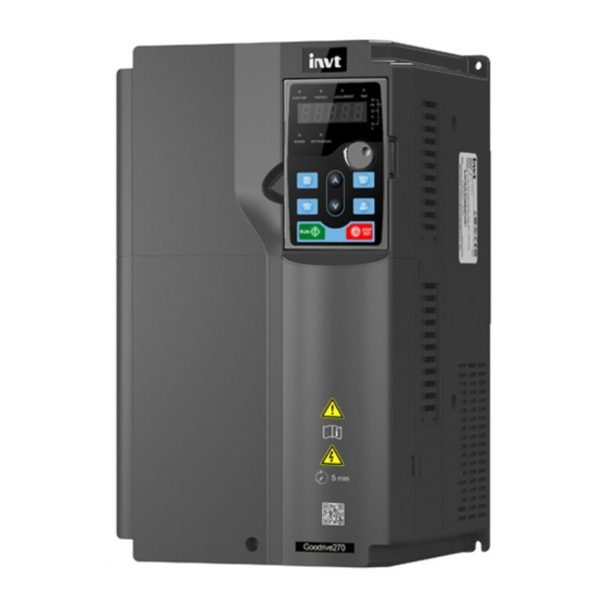
INVT Goodrive270 Series Operation Manual (372 pages)
VFD for Fan and Pump
Brand:
INVT
| Category:
Servo Drives
| Size: 26.17 MB
Table of Contents
Table of Contents
5
Safety Precautions
11
What this Chapter Contains
11
Safety Definition
11
Warning
11
Safety Guidelines
12
Delivery and Installation
12
Commissioning and Running
13
Maintenance and Component Replacement
14
Disposal
14
Quick Startup
15
What this Chapter Contains
15
Unpacking Inspection
15
Checking before Use
15
Environment Checking
15
Checking after Installation
16
Basic Commissioning
16
Product Overview
18
What this Chapter Contains
18
Basic Principles
18
Product Specifications
19
Product Nameplate
21
Model Designation Code
21
Product Ratings
22
Structure
23
Installation Guidelines
25
What this Chapter Contains
25
Mechanical Installation
25
Installation Environment
25
Installation Direction
26
Mounting Method
26
Installing One VFD
27
Multiple-VFD Installation
28
Vertical Installation
28
Tilted Installation
29
Cabinet Installation
29
Standard Wiring of the Main Circuit
38
Main Circuit Wiring Diagram
38
Main Circuit Terminal Diagram
39
Wiring Procedure for Main Circuit Terminals
44
Standard Wiring of the Control Circuit
45
Wiring Diagram of Basic Control Circuit
45
Input/Output Signal Connection Diagram
47
External Optional Keypad Wiring
48
Wiring Protection
49
Basic Operation Guidelines
51
What this Chapter Contains
51
Keypad Operation
51
LED Keypad (BOP-270) Display and Operation
51
Displaying Stopped-State Parameters
53
Displaying Running-State Parameters
54
Displaying Fault Alarms
54
Editing Function Codes
54
Modifying Function Codes
55
Setting a Password for the VFD
55
Viewing VFD Status
56
LCD Keypad (SOP-270) Display and Operation
56
Displaying Stopped-State Parameters
60
Displaying Running-State Parameters
60
Displaying Fault Information
61
Entering/Exiting Menus
61
Editing a Parameter List
66
Adding Parameters to the Parameter List Displayed in Stopped/Running State
67
Adding Parameters to the User Defined Parameter List
67
Editing User Defined Parameters
68
Editing Parameters in Parameter Groups
69
Monitoring States
69
Autotuning Motor Parameters
70
Backing up Parameters
70
System Settings
70
Power-On Setup Wizard
71
Basic Operation Description
73
What this Section Describes
73
Common Commissioning Procedure
73
Vector Control
77
Space Voltage Vector Control Mode
83
Torque Control
91
Motor Parameters
95
Start/Stop Control
101
Frequency Setting
105
Analog Input
110
Analog Output
112
Digital Input
116
Digital Output
125
Simple PLC
130
Multi-Step Speed Running
133
PID Control
135
Water Pump Control
140
PID Function Only for Water Supply
152
Segmented Water Pressure
153
Automatic Sleep
153
Pump Cleaning
154
Water Pipe Break Detection
156
Water Pipe Soft Padding
156
Freezing Protection
157
Condensation Protection
158
Function Parameter List
159
What this Chapter Contains
159
P00 Group-Basic Functions
160
P01 Group-Start and Stop Control
164
P02 Group--Parameters of Motor 1
171
P03 Group--Vector Control of Motor 1
174
P04 Group-V/F Control
181
P05 Group--Input Terminals
189
P06 Group-Output Terminals
197
P07 Group--Human-Machine Interface
202
P08 Group--Enhanced Functions
209
P09 Group--PID Control
217
P10 Group--Simple PLC and Multi-Step Speed Control
221
P11 Group-Protection Parameters
225
P12 Group--Parameters of Motor 2
235
P13 Group--SM Control
238
P14 Group--Serial Communication
240
P15 Group--Functions of Communication Expansion Card 1
242
P16 Group--Functions of Communication Expansion Card 2
242
P17 Group--Status Viewing
243
P19 Group--Expansion Card Status Viewing
248
P23 Group--Vector Control of Motor 2
249
P25 Group--Input Functions of Expansion I/O Card
251
P26 Group--Output Functions of Expansion I/O Card
253
P28 Group--Master/Slave Control
255
P89 Group--HVAC Status Viewing
256
P90 Group--PID1 Control
258
P91 Group--PID2 Control
262
P92 Group--Real-Time Clock and Timer (Available at Use of LCD Keypad)
266
P93 Group--Fire Control
266
P94 Group--HVAC
267
P95 Group--Segmented Water Pressure (Available at Use of LCD Keypad)
272
P96 Group--HVAC Protection
272
Troubleshooting
276
What this Chapter Contains
276
Indications of Alarms and Faults
276
Fault Reset
276
Fault History
276
Faults and Solutions
276
Other Status
283
Analysis on Common Faults
284
Motor Fails to Work
284
Motor Vibrates
285
Overvoltage
286
Undervoltage
286
Motor Overheating
287
VFD Overheating
288
Motor Stalls During ACC
289
Overcurrent
290
Countermeasures on Common Interference
290
Interference on Meter Switches and Sensors
290
Interference on RS485 Communication
292
Failure to Stop and Indicator Shimmering Due to Motor Cable Coupling
293
Leakage Current and Interference on RCD
293
Live Device Chassis
294
Maintenance
296
What this Chapter Contains
296
Periodical Inspection
296
Cooling Fan
299
Capacitor
301
Capacitor Reforming
301
Electrolytic Capacitor Replacement
302
Power Cable
302
Communication Protocol
303
What this Chapter Contains
303
Modbus Protocol Introduction
303
Application of Modbus
303
Rs485
303
RTU Mode
306
RTU Command Code and Communication Data
309
Command Code 03H, Reading N Words (Continuously up to 16 Words)
309
Command Code 06H, Writing a Word
311
Command Code 10H, Continuous Writing
312
Data Address Definition
313
Fieldbus Scale
317
Error Message Response
318
Read/Write Operation Examples
319
Common Communication Faults
324
Appendix A Expansion Card
325
Model Definition
325
Dimensions and Installation
326
Wiring
329
I/O Cards
330
Ec-Io501-00
330
Ec-Io503-00
332
Communication Cards
334
PROFIBUS-DP Communication Card (EC-TX503D)
334
CAN Multi-Protocol Communication Card (EC-TX505C)
336
PROFINET Communication Card (EC-TX509C)
337
Appendix B Technical Data
340
What this Chapter Contains
340
Derated Application
340
Capacity
340
Derating
340
Grid Specifications
341
Motor Connection Data
341
EMC Compatibility and Motor Cable Length
341
Application Standards
342
CE Marking
342
EMC Compliance Declaration
342
EMC Regulations
342
Appendix C Dimension Drawings
344
What this Chapter Contains
344
Keypad Structure
344
Structure Diagram
344
Keypad Mounting Bracket
344
VFD Structure
345
Dimensions of AC 3PH 380V VFD Models
346
Wall-Mounting Dimensions
346
Flange Mounting Dimensions
348
Floor Mounting Dimensions
351
Appendix D Optional Peripheral Accessories
354
What this Chapter Contains
354
Wiring of Peripheral Accessories
354
Power Supply
355
Cables
355
Power Cables
355
Control Cables
356
Recommended Cable Size
357
Cable Arrangement
360
Insulation Inspection
360
Breakers and Electromagnetic Contactors
361
Reactors
362
Filters
364
Input Filters
364
Output Filters
367
List of Other Optional Accessories
368
Appendix E Energy Efficiency Data
369
Appendix F Further Information
371
Product and Service Queries
371
Feedback on INVT VFD Manuals
371
Documents on the Internet
371
Advertisement
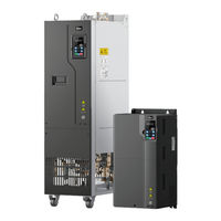
INVT Goodrive270 Series Operation Manual (336 pages)
VFD for Fan and Pump
Brand:
INVT
| Category:
Water Pump
| Size: 7.43 MB
Table of Contents
Table of Contents
5
Contents
9
Safety Precautions
11
What this Chapter Contains
11
Safety Definition
11
Warning
11
Safety Guidelines
12
Delivery and Installation
12
Commissioning and Running
13
Maintenance and Component Replacement
14
Disposal
14
Quick Startup
15
What this Chapter Contains
15
Unpacking Inspection
15
Checking before Use
15
Environment Checking
15
Checking after Installation
16
Basic Commissioning
16
Product Overview
17
What this Chapter Contains
17
Basic Principles
17
Product Specifications
18
Product Nameplate
20
Model Designation Code
20
Product Ratings
21
Structure
21
Installation Guidelines
23
What this Chapter Contains
23
Mechanical Installation
23
Installation Environment
23
Installation Direction
24
Installation Method
25
Single-Unit Installation
26
Multiple-VFD Installation
26
Vertical Installation
27
Tilted Installation
28
In-Cabinet Installation
28
Standard Wiring of the Main Circuit
37
Wiring Diagram of the Main Circuit
37
Terminal Diagram of the Main Circuit
38
Wiring Procedure for Main Circuit Terminals
42
Standard Wiring of the Control Circuit
43
Wiring Diagram of Basic Control Circuit
43
Input/Output Signal Connection Diagram
45
Wiring Protection
46
Basic Operation Guidelines
48
What this Chapter Contains
48
Keypad Introduction
48
Keypad Display
50
Displaying Stopped-State Parameters
50
Displaying Running-State Parameters
51
Displaying Fault Alarms
51
Editing Function Codes
51
Operation Procedure
52
Modifying Function Codes
52
Setting a Password for the VFD
52
Viewing VFD Status
53
Basic Operation Description
53
What this Section Describes
53
Common Commissioning Procedure
53
Vector Control
57
Space Voltage Vector Control Mode
63
Torque Control
72
Motor Parameters
76
Start/Stop Control
82
Frequency Setting
86
Analog Input
90
Analog Output
92
Digital Input
96
Digital Output
105
Simple PLC
109
Multi-Step Speed Running
111
PID Control
113
Run at Wobbling Frequency
119
HVAC Function
120
Electric Wiring and Timing Diagram of HVAC Function
125
Motor Reducing
129
Fault Handling
130
Function Parameter List
134
What this Chapter Contains
134
P00 Group Basic Functions
135
P01 Group Start and Stop Control
139
P02 Group Parameters of Motor 1
146
P03 Group Vector Control of Motor 1
149
P04 Group V/F Control
155
P05 Group Input Terminals
163
P06 Group Output Terminals
171
P07 Group Human-Machine Interface
176
P08 Group Enhanced Functions
183
P09 Group PID Control
191
P10 Group Simple PLC and Multi-Step Speed Control
196
P11 Group Protection Parameters
199
P12 Group Parameters of Motor 2
210
P13 Group SM Control
212
P14 Group Serial Communication
214
P15 Group Communication Expansion Card 1 Functions
216
P16 Group Communication Expansion Card 2 Functions
217
P17 Group Status Viewing
217
P19 Group Expansion Card Status Viewing
222
P23 Group Vector Control of Motor 2
223
P25 Group I/O Card Input Functions
225
P26 Group I/O Card Output Functions
227
P28 Group Master/Slave Control
230
P89 Group HVAC Status Viewing
231
P90 Group PID1 Control
233
P91 Group PID2 Control
237
P92 Group Real-Time Clock and Timer (Available at Use of LCD Keypad)
240
P93 Group Fire Control
241
P94 Group HVAC
241
P95 Group Segmented Water Pressure
246
P96 Group HVAC Protection
246
Troubleshooting
250
What this Chapter Contains
250
Indications of Alarms and Faults
250
Fault Reset
250
Fault History
250
Faults and Solutions
250
Other Status
257
Analysis on Common Faults
258
Motor Fails to Work
258
Motor Vibrates
259
Overvoltage
260
Undervoltage
261
Motor Overheating
262
VFD Overheating
263
Motor Stalls During ACC
264
Overcurrent
265
Countermeasures on Common Interference
265
Interference on Meter Switches and Sensors
265
Interference on RS485 Communication
267
Failure to Stop and Indicator Shimmering Due to Motor Cable Coupling
268
Leakage Current and Interference on RCD
268
Live Device Chassis
269
Maintenance
270
What this Chapter Contains
270
Periodical Inspection
270
Cooling Fan
273
Capacitor
274
Capacitor Reforming
274
Electrolytic Capacitor Replacement
275
Power Cable
275
Communication
276
What this Chapter Contains
276
Modbus Protocol Introduction
276
Application of Modbus
276
Rs485
276
RTU Mode
279
RTU Command Code and Communication Data
282
Command Code 03H, Reading N Words (Continuously up to 16 Words)
282
Command Code 06H, Writing a Word
284
Command Code 08H, Diagnosis
285
Command Code 10H, Continuous Writing
286
Data Address Definition
287
Fieldbus Scale
291
Error Message Response
292
Read/Write Operation Examples
293
Common Communication Faults
298
Appendix A Expansion Card
299
Model Definition
299
Dimensions and Installation
301
Wiring
303
IO Expansion Card (EC-IO501-00)
304
Communication Cards
306
PROFIBUS-DP Communication Card (EC-TX503)
306
Ethernet Communication Card (EC-TX504)
308
Communication Card (EC-TX511)
309
PROFINET Communication Card (EC-TX509)
310
GPRS Iot Card EC-IC501-2
312
Appendix B Technical Data
314
What this Chapter Contains
314
Derated Application
314
Capacity
314
Derating
314
Grid Specifications
315
Motor Connection Data
315
EMC Compatibility and Motor Cable Length
315
Application Standards
315
CE Marking
316
EMC Compliance Declaration
316
EMC Regulations
316
VFD Category of C2
317
VFD Category of C3
317
Appendix C Dimension Drawings
318
What this Chapter Contains
318
Keypad Structure
318
Structure Diagram
318
Keypad Mounting Bracket
318
VFD Structure
319
Dimensions of AC 3PH 380V VFD Models
319
Wall-Mounting Dimensions
319
Flange Mounting Dimensions
322
Floor Mounting Dimensions
323
Appendix D Optional Peripheral Accessories
325
What this Chapter Contains
325
Wiring of Peripheral Accessories
325
Power Supply
326
Cable
326
Powe Cable
326
Control Cables
327
Recommended Cable Size
328
Cable Arrangement
329
Insulation Inspection
330
Breaker and Electromagnetic Contactor
330
Reactor
331
Filters
333
Filter Model Description
333
Filter Model Selection
333
Appendix E Further Information
335
Product and Service Queries
335
Feedback on INVT VFD Manuals
335
Documents on the Internet
335
Advertisement
Related Products
INVT GD270-030-4
INVT GD270-045-4
INVT GD270-055-4
INVT GD270-110-4
INVT GD270-160-4
INVT GD270-185-4
INVT GD270-250-4
INVT GD270-280-4
INVT GD270-500-4
INVT GD270-450-4
INVT Categories
Inverter
DC Drives
Servo Drives
Controller
I/O Systems
More INVT Manuals
Login
Sign In
OR
Sign in with Facebook
Sign in with Google
Upload manual
Upload from disk
Upload from URL