Sign In
Upload
Manuals
Brands
INVT Manuals
Water Pump
GD270-450-4
User Manuals: INVT GD270-450-4 VFD Pump Controller
Manuals and User Guides for INVT GD270-450-4 VFD Pump Controller. We have
1
INVT GD270-450-4 VFD Pump Controller manual available for free PDF download: Operation Manual
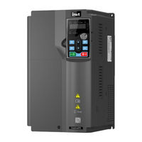
INVT GD270-450-4 Operation Manual (336 pages)
VFD for Fan and Pump
Brand:
INVT
| Category:
Water Pump
| Size: 7 MB
Table of Contents
Table of Contents
5
Contents
9
Safety Precautions
11
What this Chapter Contains
11
Safety Definition
11
Warning
11
Safety Guidelines
12
Delivery and Installation
12
Commissioning and Running
13
Maintenance and Component Replacement
14
Disposal
14
Quick Startup
15
What this Chapter Contains
15
Unpacking Inspection
15
Checking before Use
15
Environment Checking
15
Checking after Installation
16
Basic Commissioning
16
Product Overview
17
What this Chapter Contains
17
Basic Principles
17
Product Specifications
18
Product Nameplate
20
Model Designation Code
20
Product Ratings
21
Structure
21
Installation Guidelines
23
What this Chapter Contains
23
Mechanical Installation
23
Installation Environment
23
Installation Direction
24
Installation Method
25
Single-Unit Installation
26
Multiple-VFD Installation
26
Vertical Installation
27
Tilted Installation
28
In-Cabinet Installation
28
Standard Wiring of the Main Circuit
37
Wiring Diagram of the Main Circuit
37
Terminal Diagram of the Main Circuit
38
Wiring Procedure for Main Circuit Terminals
42
Standard Wiring of the Control Circuit
43
Wiring Diagram of Basic Control Circuit
43
Input/Output Signal Connection Diagram
45
Wiring Protection
46
Basic Operation Guidelines
48
What this Chapter Contains
48
Keypad Introduction
48
Keypad Display
50
Displaying Stopped-State Parameters
50
Displaying Running-State Parameters
51
Displaying Fault Alarms
51
Editing Function Codes
51
Operation Procedure
52
Modifying Function Codes
52
Setting a Password for the VFD
52
Viewing VFD Status
53
Basic Operation Description
53
What this Section Describes
53
Common Commissioning Procedure
53
Vector Control
57
Space Voltage Vector Control Mode
63
Torque Control
72
Motor Parameters
76
Start/Stop Control
82
Frequency Setting
86
Analog Input
90
Analog Output
92
Digital Input
96
Digital Output
105
Simple PLC
109
Multi-Step Speed Running
111
PID Control
113
Run at Wobbling Frequency
119
HVAC Function
120
Electric Wiring and Timing Diagram of HVAC Function
125
Motor Reducing
129
Fault Handling
130
Function Parameter List
134
What this Chapter Contains
134
P00 Group Basic Functions
135
P01 Group Start and Stop Control
139
P02 Group Parameters of Motor 1
146
P03 Group Vector Control of Motor 1
149
P04 Group V/F Control
155
P05 Group Input Terminals
163
P06 Group Output Terminals
171
P07 Group Human-Machine Interface
176
P08 Group Enhanced Functions
183
P09 Group PID Control
191
P10 Group Simple PLC and Multi-Step Speed Control
196
P11 Group Protection Parameters
199
P12 Group Parameters of Motor 2
210
P13 Group SM Control
212
P14 Group Serial Communication
214
P15 Group Communication Expansion Card 1 Functions
216
P16 Group Communication Expansion Card 2 Functions
217
P17 Group Status Viewing
217
P19 Group Expansion Card Status Viewing
222
P23 Group Vector Control of Motor 2
223
P25 Group I/O Card Input Functions
225
P26 Group I/O Card Output Functions
227
P28 Group Master/Slave Control
230
P89 Group HVAC Status Viewing
231
P90 Group PID1 Control
233
P91 Group PID2 Control
237
P92 Group Real-Time Clock and Timer (Available at Use of LCD Keypad)
240
P93 Group Fire Control
241
P94 Group HVAC
241
P95 Group Segmented Water Pressure
246
P96 Group HVAC Protection
246
Troubleshooting
250
What this Chapter Contains
250
Indications of Alarms and Faults
250
Fault Reset
250
Fault History
250
Faults and Solutions
250
Other Status
257
Analysis on Common Faults
258
Motor Fails to Work
258
Motor Vibrates
259
Overvoltage
260
Undervoltage
261
Motor Overheating
262
VFD Overheating
263
Motor Stalls During ACC
264
Overcurrent
265
Countermeasures on Common Interference
265
Interference on Meter Switches and Sensors
265
Interference on RS485 Communication
267
Failure to Stop and Indicator Shimmering Due to Motor Cable Coupling
268
Leakage Current and Interference on RCD
268
Live Device Chassis
269
Maintenance
270
What this Chapter Contains
270
Periodical Inspection
270
Cooling Fan
273
Capacitor
274
Capacitor Reforming
274
Electrolytic Capacitor Replacement
275
Power Cable
275
Communication
276
What this Chapter Contains
276
Modbus Protocol Introduction
276
Application of Modbus
276
Rs485
276
RTU Mode
279
RTU Command Code and Communication Data
282
Command Code 03H, Reading N Words (Continuously up to 16 Words)
282
Command Code 06H, Writing a Word
284
Command Code 08H, Diagnosis
285
Command Code 10H, Continuous Writing
286
Data Address Definition
287
Fieldbus Scale
291
Error Message Response
292
Read/Write Operation Examples
293
Common Communication Faults
298
Appendix A Expansion Card
299
Model Definition
299
Dimensions and Installation
301
Wiring
303
IO Expansion Card (EC-IO501-00)
304
Communication Cards
306
PROFIBUS-DP Communication Card (EC-TX503)
306
Ethernet Communication Card (EC-TX504)
308
Communication Card (EC-TX511)
309
PROFINET Communication Card (EC-TX509)
310
GPRS Iot Card EC-IC501-2
312
Appendix B Technical Data
314
What this Chapter Contains
314
Derated Application
314
Capacity
314
Derating
314
Grid Specifications
315
Motor Connection Data
315
EMC Compatibility and Motor Cable Length
315
Application Standards
315
CE Marking
316
EMC Compliance Declaration
316
EMC Regulations
316
VFD Category of C2
317
VFD Category of C3
317
Appendix C Dimension Drawings
318
What this Chapter Contains
318
Keypad Structure
318
Structure Diagram
318
Keypad Mounting Bracket
318
VFD Structure
319
Dimensions of AC 3PH 380V VFD Models
319
Wall-Mounting Dimensions
319
Flange Mounting Dimensions
322
Floor Mounting Dimensions
323
Appendix D Optional Peripheral Accessories
325
What this Chapter Contains
325
Wiring of Peripheral Accessories
325
Power Supply
326
Cable
326
Powe Cable
326
Control Cables
327
Recommended Cable Size
328
Cable Arrangement
329
Insulation Inspection
330
Breaker and Electromagnetic Contactor
330
Reactor
331
Filters
333
Filter Model Description
333
Filter Model Selection
333
Appendix E Further Information
335
Product and Service Queries
335
Feedback on INVT VFD Manuals
335
Documents on the Internet
335
Advertisement
Advertisement
Related Products
INVT GD270-400-4
INVT GD270-030-4
INVT GD270-045-4
INVT GD270-055-4
INVT GD270-110-4
INVT GD270-160-4
INVT GD270-185-4
INVT GD270-250-4
INVT GD270-280-4
INVT GD270-500-4
INVT Categories
Inverter
DC Drives
Servo Drives
Controller
UPS
More INVT Manuals
Login
Sign In
OR
Sign in with Facebook
Sign in with Google
Upload manual
Upload from disk
Upload from URL