Sign In
Upload
Manuals
Brands
Intel Manuals
Server
H2000WP
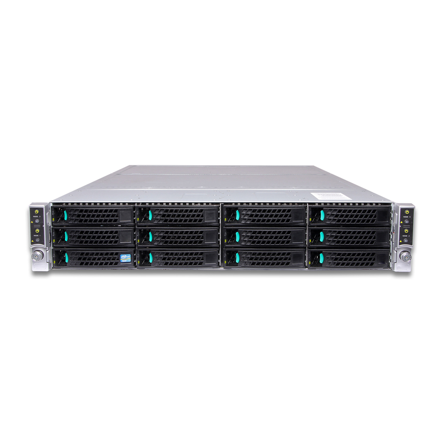
Intel H2000WP Server System Manuals
Manuals and User Guides for Intel H2000WP Server System. We have
3
Intel H2000WP Server System manuals available for free PDF download: Technical Manual, Service Manual, Quick Installation User's Manual
Intel H2000WP Technical Manual (117 pages)
Brand:
Intel
| Category:
Server
| Size: 3 MB
Table of Contents
Revision History
2
Table of Contents
4
1 Introduction
15
Chapter Outline
15
Server Board Use Disclaimer
16
2 Product Overview
17
Table 1. System Feature Set
17
Table 2. System SKU Matrix
18
Figure 1. System Overview (Air Duct Is Removed)
19
Figure 2. Compute Node Scheme (Rear View)
19
System Dimensions
19
System Views
19
Table 3. Chassis Dimension (SKU: H2312WPJR)
19
System Level Environmental Limits
20
Table 4. Chassis Dimension (SKU: H2216WPJR)
20
Table 5. System Environmental Limits Summary
20
High Temperature Ambience (HTA) Support
21
Table 6. Ambient Temperature Versus System Configuration
23
Figure 7. Intel
24
Set Throttling Mode
24
Altitude
25
Fan PWM Offset
25
Quiet Fan Idle Mode
25
Set Fan Profile
25
Thermal Sensor Input for Fan Speed Control
25
Figure 3. Fan Speed Control Structure
26
Hard Drive and Peripheral Bays
26
Figure 4. Intel Server System H2312WP Drive Bay Overview
27
Figure 5. Intel Server System H2216WP Drive Bay Overview
27
Server Board Overview
27
Figure 6. Intel
28
Figure 8. Back Panel Feature Overview
28
Figure 9. Light-Guided Diagnostic LED Locations
29
Figure 10. System Bezel Front View
30
Front Bezel Support
30
Rack and Cabinet Mounting Options
30
3 Power Sub-System
31
Mechanical Overview
31
AC Power Supply Unit Dimension Overview
31
AC Power Supply Unit General Data
31
Figure 11. AC Power Supply Unit Dimension Overview
31
AC Input Connector
32
AC Power Cord Specification Requirements
32
Power Supply Unit DC Output Connector
32
Table 8. Specification Data for AC Power Supply Unit
32
Table 9. AC Power Cord Specification
32
Table 10. DC Output Power Connector
32
Handle Retention
33
LED Marking and Identification
33
Power Cage with Power Distribution Board
33
Table 11. Power Supply Status LED
33
Power Cage Output Pin Assignment
34
Figure 12. Power Cage Overview
34
Figure 13. Power Distribution Board
35
Table 12. Pin Assignment of Power Output Connector
35
Table 13. Pin Assignment of Control Signal Connector
35
AC Input Specification
36
Input Voltage and Frequency
36
AC Input Power Factor
36
Efficiency
36
Table 14. AC Input Rating
36
Table 15. Typical Power Factor
36
AC Line Fuse
37
AC Line Inrush
37
AC Line Dropout/Holdup
37
AC Line Fast Transient (EFT) Specification
37
Table 16. Platinum Efficiency Requirement
37
Table 17. AC Power Holdup Reuqirement
37
Hot Plug
38
Susceptibility Requirements
38
Electrostatic Discharge Susceptibility
38
Fast Transient/Burst
38
Radiated Immunity
38
Surge Immunity
38
Table 18. Performance Criteria
38
AC Line Transient Specification
39
Power Recovery
39
Voltage Interruptions
39
AC Line Isolation
39
AC Power Inlet
39
Table 19. AC Line Sag Transient Performance
39
Table 20. AC Line Surge Transient Performance
39
DC Output Specification
40
Output Power/Currents
40
Standby Output
40
Voltage Regulation
40
Figure 14. AC Power Cord Specification
40
Table 21. Load Ratings for Single Power Supply Unit
40
Table 22. Voltage Regulation Limits
40
Dynamic Loading
41
Capacitive Loading
41
Ripple/Noise
41
Grounding
41
Table 23. Transient Load Requirements
41
Table 24. Capacitive Loading Conditions
41
Table 25. Ripple and Noise
41
Closed Loop Stability
42
Residual Voltage Immunity in Standby Mode
42
Common Mode Noise
42
Soft Starting
42
Zero Load Stability Requirement
42
Hot Swap Requirement
42
Forced Load Sharing
43
Timing Requirement
43
Table 26. Timing Requirement
43
Power Supply Cold Redundancy Support
44
Figure 15. Turn On/Off Timing (Power Supply Signals)
44
Table 7. Intel
44
1200W CRPS Cold Redundancy
45
System Behavior with One Power Supply AC Lost or Failed
45
Control and Indicator Functions
45
Table 27. 1200W CRPS Cold Redundancy Threshold
45
Table 28. 1600W CRPS Cold Redundancy Threshold
45
Table 29. System Behavior with One Power Supply AC Lost or Failed
45
PSON# Input Signal
46
PWOK (Power Good) Output Signal
46
Smbalert# Signal
46
Table 30. PSON# Signal Characteristics
46
Table 31. PWOK Signal Characteristics
46
Protection Circuits
47
Current Limit (OCP)
47
Over Voltage Protection (OVP)
47
Over Thermal Protection
47
Table 32. Smbalert# Signal Characteristics
47
Table 33. over Current Protection
47
Table 34. over Voltage Protection (OVP) Limits
47
Pmbus
48
PSU Address Lines A0
48
Figure 16. Power Supply Device Address
48
Table 35. PSU Addressing
48
Accuracy
49
Power Management Policy
49
Figure 17. Pmbus* Monitoring Accuracy
49
Table 36. Pmbus* Accuracy
49
4 Cooling Sub-System
50
Processor Heatsink
50
Node Cooling Fans
51
Figure 18. Processor Heatsink Overview
51
Figure 19. Node Fan Set and Power/Control Connection
52
Power Supply Fan
53
Air Duct Module
53
Drive Bay Population Requirement
53
Figure 20. Compute Node Air Duct
53
Table 37. 8-Pin Connector Pin-Out for Node Dual Rotor Fans
53
5 System Boards in the Node Tray
55
Node Docking Board
55
Overview of Node Docking Board
55
Figure 21. Compute Node Tray Overview
55
Figure 22. Node Docking Board
55
Pinout Definition on Node Docking Board
56
Table 38. Main Power Input Connector
56
Table 39. Fan Control Signal Connector
56
Table 40. Node Fan Connector
56
Bridge Board
57
Overview of Bridge Board
57
Figure 23. Bridge Board Overview
57
Table 41. Main Power Output Connector
57
Pinout Definition on Bridge Board
58
Figure 24. Connectors on Bridge Board
58
Table 42. Card Edge Connector Pinout
58
Table 43. AHCI SATA0 DOM Connector Pinout
59
6Gbs SAS Support Option 1
60
Overview of Bridge Board
60
Table 44. USB 2.0 Type-A Connector Pinout
60
Table 45. 5V_AUX Power Connector Pinout
60
Figure 25. SAS 6Gbs Bridge Board Overview
61
Pinout Definition on SAS 6Gbs Bridge Board
62
Figure 26. Connectors and Components on Spare Bridge Board
62
Table 46. Pinout of Card Edge to Baseboard
62
Table 47. Pinout of Card Edge to Hot Swap Back Plane
62
6Gbs SAS Support Option 2
63
Bridge Board
63
Table 48. Pinout of Mini SAS Connector
63
Figure 27. Overview of the Bridge Board
64
Figure 28. Connectors on the Bridge Board
64
Table 49. Card Edge Pin-Out of Bridge Board to SAS Controller
64
Riser Card
65
Figure 29. Overview of the Riser Card
65
Table 50. Card Edge Pin-Out of Riser Card to SAS Controller
65
Table 51. Card Edge Pin-Out of Riser Card to Pcie Slot2 of Baseboard
66
SAS Controller Module
67
Figure 30. SAS Controller Module Overview
68
6 Hard Disk Drive Support
69
Hard Disk Drive Bays Scheme
69
Figure 31. HDD Scheme for H2312WPGR
69
Figure 32. HDD Scheme for H2216WPGR
69
Hard Drive Carrier
70
Hot Swap Hard Drive Support
70
Figure 33. 3.5-Inch HDD Assembly Overview
70
Figure 34. 2.5-Inch HDD Assembly Overview
70
Backplane Feature Set
71
3.5" Hot Swap Backplane Connector Scheme
72
Backplane Block Diagram
72
Figure 35. Passive Backplane Block Diagram (for One Node)
72
Figure 36. 3.5" Backplane Component and Connectors (Front View)
72
Figure 37. 3.5" Backplane Component and Connectors (Back View)
73
Hot Swap Backplane Connector Scheme
73
Figure 38. 2.5" Backplane Component and Connectors (Front View)
74
Figure 39. 2.5" Backplane Component and Connectors (Back View)
74
Backplane Connector Definition
75
Backplane LED Support
75
Figure 40. Hard Drive Carrier LED
75
Table 52. Hard Drive Carrier Status LED Functions
75
Table 53. Hard Drive Carrier Activity LED Functions
75
Table 54. Backplane Input Power Connector Pin-Out
76
Table 55. 2-Blade Compute Node Power Connector Pin-Out
76
Table 56. 2X40 Pin Connector Pin-Out for Node Bridge Board
76
Table 57. Front Panel Connector Pin-Out
77
Table 58. Power Supply Control Connector Pin-Out
78
7 Front Panel Control and Indicators
79
Figure 41. Front Control Panel
79
Control Panel Button
80
Control Panel LED Indicators
80
Table 59. Front Control Button Function
80
Table 60. Front LED Indicator Functions
80
Power/Sleep LED
81
System Status LED
81
Table 61. Power LED Operation
81
Table 62. System Status LED Operation
81
System Status LED - BMC Initialization
82
8 Configuration Jumpers
83
Figure 42. Jumper Locations and Functions
83
Force Integrated BMC Update (J6B1)
84
Table 63. Force Integrated BMC Update Jumper
84
Table 64. Force Integrated BMC Update Jumper
84
Force ME Update (J1E2)
85
Password Clear (J1E3)
85
Table 65. Force ME Update Jumper
85
Table 66. BIOS Password Clear Jumper
85
BIOS Recovery Mode (J1E1)
86
Table 67. BIOS Recovery Mode Jumper
86
Reset BIOS Settings (J1D5)
87
Table 68. Reset BIOS Jumper
87
9 PCI Express* Riser Card and Assembly
89
PCI Express* Riser for Slot 1
89
Overview of PCI-Express Riser
89
Pinout Definition on Slot 1 Riser
89
Figure 43. PCI Express* Riser for Riser Slot 1
89
Table 69. Riser Card Edge Pinout
89
Table 70. PCI Express* Slot Pinout on Riser Card
91
PCI Express* Riser with IOM Carrier for Slot 2 (Optional)
93
Overview of PCI-E Riser with IOM Carrier
93
Figure 44. PCI Express* Riser with Bracket for Riser Slot 2
94
Figure 45. IOM Carrier
94
Table 71. Dedicated NIC Port LED Functionality
94
Pinout Definition on Slot 2 Riser and IOM Carrier
95
Table 72. Riser Card Edge Pinout
95
Table 73. PCI Express* Slot Pinout on Riser Card
97
Table 74. IO Module Slot on Carrier
99
Appendix A: Integration and Usage Tips
101
Appendix B: POST Code LED Decoder
102
Figure 46. Diagnostic LED Location
102
Table 75. POST Code Diagnostic LED Location
102
Table 76. POST Progress Code LED Example
103
Table 77. MRC Fatal Error Codes
103
Table 78. MRC Progress Codes
104
Table 79. POST Progress Codes
104
Appendix C: Video POST Code Errors
108
Table 80. POST Error Message and Handling
108
Post Error Beep Codes
113
Glossary
114
Reference Documents
117
Advertisement
Intel H2000WP Service Manual (88 pages)
Brand:
Intel
| Category:
Server
| Size: 3 MB
Table of Contents
Safety Information
3
Preface
5
Table of Contents
7
1 Server System Features
15
Server System Feature Overview
15
Figure 1. Intel Server System H2000WP Family (H2312WP as Demonstrated)
15
Table 3. Intel ® Server System H2000WP Feature Summary
15
Server System Components
17
Figure 2. Intel Server System H2000WP Overview (H2312WP as Demonstrated)
18
Figure 3. Front View of Intel
18
Figure 4. Front View of Intel
18
Front Panel
19
Figure 5. Rear View of Intel
19
Figure 6. HDD Array Scheme on Intel
19
Figure 7. HDD Array Scheme on Intel
19
Back Panel
20
Figure 8. Front Panel Options
20
Figure 9. Back Panel Feature Identification Per Compute Node
20
Server Board Components
21
Figure 10. Server Board S2600WPQ Connector and Component Locations
21
Intel ® Light-Guided Diagnostics
22
Figure 11. Intel Light-Guided Diagnostic Leds - Server Board
22
System Jumpers
23
Figure 12. Configuration Jumpers
23
Bezel
24
Figure 13. Front View of System Bezel
24
Hard Disk Drive Carriers
24
Hot-Swap SAS/SATA Backplane
24
Table 4. Hard Disk Drive Options
24
Figure 14. 12 X 3.5-Inch Hard Drive Backplane Components (Front View)
25
Figure 15. 12 X 3.5-Inch Hard Drive Backplane Components (Rear View)
25
Advanced Management Options
26
Figure 16. 16 X 2.5-Inch Hard Drive Backplane Components (Front View)
26
Figure 17. 16 X 2.5-Inch Hard Drive Backplane Components (Rear View)
26
Dummy Tray Cover
27
2 Hardware Installations and Upgrades
28
Before You Begin
28
Tools and Supplies Needed
28
System Reference
28
Cable Routing
28
For Cable Connection Inside Node Tray
29
Removing and Installing the Front Bezel
29
Removing the Front Bezel
29
Installing the Front Bezel
29
Figure 19. Cable Routing Inside Node Tray
29
Figure 20. Removing the Front Bezel
29
Removing and Installing the System Top Cover
30
Removing the System Top Cover
30
Figure 21. Installing the Front Bezel
30
Installing the System Cover
31
Removing and Installing the Compute Node Tray
31
Figure 22. Removing the System Top Cover
31
Figure 23. Installing the System Cover
31
Installing the Node Tray
32
Removing the Node Tray
32
Removing and Installing the Redundant Power Supply Unit
32
Figure 24. Pulling out the Node Tray
32
Figure 25. Installing the Node Tray
32
Installing the Power Supply Unit
33
Removing the Power Supply Unit
33
Removing and Installing the Node Tray Air Duct
33
Figure 26. Removing the PSU
33
Figure 27. Installing the PSU
33
Figure 28. Removing the Air Duct
34
Installing the Air Duct
34
Removing the Air Duct
34
Figure 29. Installing the Air Duct
35
Figure 30. Transparent Isolation Film for Air Duct
35
Transparent Mylar Installation
35
Removing and Installing Processor
36
Removing Processor Heatsink(S)
36
Installing the Processor
36
Figure 31. Removing Processor Heatsink
36
Figure 32. Installing Processor - Open the Socket Lever
37
Figure 33. Installing Processor - Open the Load Plate
37
Figure 34. Installing Processor - Install the Processor
37
Installing Processor Heatsink(S)
38
Figure 35. Installing Processor - Remove the Cover
38
Figure 36. Installing Processor - Close the Load Plate
38
Figure 37. Installing Processor - Latch the Locking Lever
38
Removing the Processor
39
Installing and Removing Memory
39
Installing Memory
39
Figure 38. Installing Processor Heatsink
39
Removing Memory
40
Installing and Removing Hot-Swap Hard Drive
40
Installing a Hard Disk Drive into 3.5" Hard Drive Carrier
40
Figure 39. Installing Memory
40
Figure 40. Installing Hard Disk Drive - Installing 3.5" HDD to Carrier
40
Installing a Hard Disk Drive into 2.5" Hard Drive Carrier
41
Figure 41. Installing Hard Disk Drive - Inserting 3.5" HDD Assembly
41
Figure 42. Installing Hard Disk Drive - Installing 2.5" HDD to Carrier
41
Installing and Removing the Pcie Riser Assembly
42
On Riser Slot 1
42
Installing the PCI Riser Assembly and Add-In Card
42
Figure 43. Installing Hard Disk Drive - Inserting 2.5" HDD Assembly
42
Figure 44. Assembly Riser with Bracket
42
Figure 45. Installing Riser 1 Assembly
42
Removing a PCI Add-In Card
43
Figure 46. Installing a PCI Adapter to PCI Riser 1 Assembly
43
Figure 47. Removing IOM Assembly
43
Figure 48. Removing Pcie Add-In Card Assembly
44
Figure 49. Removing Pcie Add-In Card from Riser Slot
44
Installing IOM Riser and Carrier Assembly
44
On Riser Slot 2
44
Figure 50. Installing the Riser to Bracket
45
Figure 51. Installing IO Module
45
Figure 52. Installing Assembly to Riser
45
Figure 53. Fastening the Assembly in Chassis
46
Figure 54. Unscrewing IOM Assembly
46
Removing IO Module
46
Installing and Removing the Intel
47
Remote Management Module 4 Lite
47
Installing the Intel RMM4 Lite
47
Figure 55. Removing IOM Assembly from Chassis
47
Figure 56. Removing IO Module from Assembly
47
Installing the Intel Storage Upgrade Key
48
Figure 57. Installing the Intel
48
Table 5. Intel ® RAID C600-A Storage Upgrade Key Options for S2600WP
48
Installing and Removing the Bridge Board
49
Removing the Bridge Board
49
Installing the Bridge Board
49
Figure 58. Installing the Intel Storage Upgrade Key
49
Figure 59. Removing the Bridge Board
49
Installing Spare Bridge Board with SAS 6G Solution Option 1
50
Replacing Node Bridge Board
50
Figure 60. Installing the Bridge Board
50
Connecting Mini SAS Cable between Bridge Board and RAID/SAS Controller
51
Installing SAS 6G Solution Option 2
53
Replacing Node Bridge Board
53
Installing and Removing the Node Power Docking Board
54
Removing the NPD Board
54
Installing the NPD Board
55
Installing and Removing the Fan Set in Node Tray
55
Removing the Fan Set
55
Figure 67. Removing the NPD Board
55
Figure 68. Installing the NPD Board
55
Installing the Fan Set
56
Replace Server Board
56
Removing Server Board
56
Figure 69. Removing the Node Fan Set
56
Figure 70. Installing the Server Board
56
Installing Server Board
57
Replacing the Backup Battery
58
Installing and Removing the 2.5" Backplane Board
59
Removing the 2.5" Backplane Board
59
Installing the 2.5" Backplane Board
59
Figure 76. Removing the 2.5" Backplane Board
59
Installing and Removing the 3.5" Backplane Board
60
Removing the 3.5" Backplane Board
60
Figure 77. Align the Backplane to the Clamps on the Chassis Base
60
Figure 78. Installing the 2.5" Backplane Board
60
Installing the 3.5" Backplane Board
61
Figure 79. Removing the 3.5" Backplane Board
61
Figure 80. Align the Backplane to the Clamps on the Chassis Base
61
Installing and Removing the Power Distribution Board
62
Removing the PDB
62
Figure 81. Installing the 3.5" Backplane Board
62
Figure 82. Removing the Upper PDB
62
Installing the PDB
63
Figure 83. Removing the Lower PDB
63
Figure 84. Installing the Lower PDB
63
Figure 85. Installing the Upper PDB
63
Replacing the Front Control Panel Board
64
Removing the Front Control Panel
64
Figure 86. Removing FP Assembly from Rack Handle
64
Figure 87. Disconnecting Control Panel Cable
64
Installing Front Control Panel Board
65
Figure 88. Removing Control Panel Board
65
Figure 89. Installing Control Panel Board
65
Rack Mounting the Chassis
66
Mounting the Chassis to Rack
66
Figure 90. Connecting Cable to Front Panel Board
66
Figure 91. Installing Control Panel Assembly to Rack Handle
66
Figure 92. Removing Inner Member from Slides
66
Figure 93. Installing Slides to the Rack
67
Figure 94. Installing Inner Member to the Chassis
67
Removing the Chassis from Rack
68
Figure 95. Installing the Chassis to Rack
68
Figure 96. Extending Slides to Remove the Chassis
68
Figure 97. Removing the Inner Member from the Chassis
69
3 Server Utilities
70
Using the BIOS Setup Utility
70
Starting Setup
70
Setup Navigation Keyboard Commands
70
Table 6. BIOS Setup: Keyboard Command Bar
70
Setup Screen Menu Selection Bar
71
BIOS Setup Utility Screens
71
Map of Screens and Functionality
72
Table 7. Screen Map
72
Appendix A: Technical Reference
74
Power Supply Input Voltages
74
Power Supply Output Voltages
74
System Environmental Specifications
74
Table 8. CRPS Input Voltage
74
Table 9. CRPS Output Voltage
74
Table 10. System Environmental Limits Summary
74
Appendix B: Regulatory and Compliance Information
76
Appendix C: LED Decoder
77
Table 11. POST Progress Code LED Example
77
Table 12. Diagnostic LED POST Code Decoder
78
Appendix D: Getting Help
83
Warranty Information
83
Appendix E: Intel Server Issue Report Form
84
Intel H2000WP Quick Installation User's Manual (22 pages)
Server System
Brand:
Intel
| Category:
Server
| Size: 23 MB
Table of Contents
Table of Contents
3
System Overview (Intel® Server System H2000JF Family)
6
System Overview (Intel® Server System H2000WP Family)
7
General Installation Process
8
Preparing the System
8
Install/Remove the Power Supply Unit
8
Install/Remove Computer Node Tray
8
Install/Remove Node Tray Air Duct
9
Remove Processor Heatsink(S)
9
Install the Processor(S)
10
Install Processor Heatsink(S)
11
Install Memory Modules
11
Install/Remove the Front Bezel
12
Install Hard Drives
12
Installing PCI Riser Assembly and Add-In Card on Riser Slot 1
13
Install I/O Module Riser and Carrier Assembly on Riser Slot 2
14
Install Intel® RAID C600 Upgrade Key (Optional)
14
Install Intel® Remote Management Module 4 (Optional)
14
Remove the Top Cover
15
Install Top Cover
15
Software
15
Assembling the Server System with Server Chassis H2000
16
Removing a Node Tray from a Chassis
16
Reference
17
Intel® Server Board S2600JF Component Layout
17
Intel® Server Board S2600WP Component Layout
17
Front Panel Controls and Indicators
18
Cable Routing Inside Server System H2000JF Node Tray
18
Optional Accessories
18
Cable Routing Inside Server System H2000WP Node Tray
19
Optional Accessories
19
Intel® Server System RAID Options
19
Intel® Server System RAID Options
20
Advertisement
Advertisement
Related Products
Intel H2000JF
Intel H2312JFJR
Intel H2216JFFJR
Intel H2216JFQJR
Intel H2312JFFKR
Intel H2216 KR2 Series
Intel H2216 JR Series
Intel H2312 JR Series
Intel H2312 KR2 Series
Intel H2312JFFJR
Intel Categories
Motherboard
Computer Hardware
Server
Desktop
Server Board
More Intel Manuals
Login
Sign In
OR
Sign in with Facebook
Sign in with Google
Upload manual
Upload from disk
Upload from URL