Sign In
Upload
Manuals
Brands
IEI Technology Manuals
Single board computers
HYPER-AL series
IEI Technology HYPER-AL series SBC Manuals
Manuals and User Guides for IEI Technology HYPER-AL series SBC. We have
1
IEI Technology HYPER-AL series SBC manual available for free PDF download: User Manual
IEI Technology HYPER-AL series User Manual (109 pages)
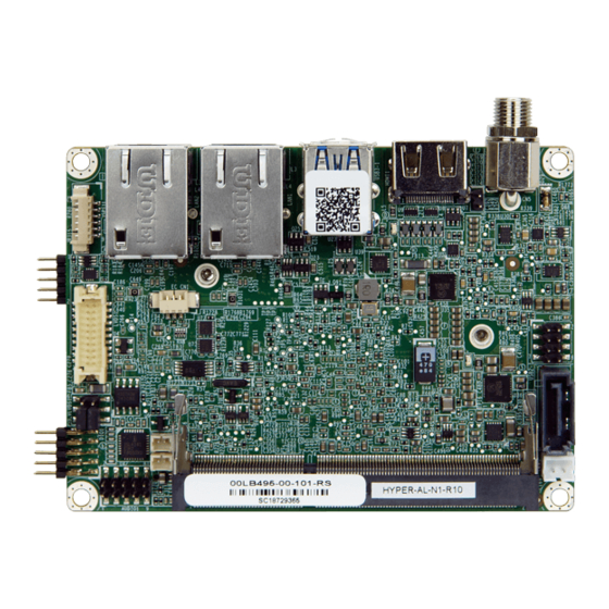
Pico-ITX SBC with 14nm Intel Celeron N3350 SoC, HDMI, LVDS, Dual PCle GbE, USB 3.0, M.2 Slots, SATA6G/s, RS-232, HD Audio and RoHS
Brand:
IEI Technology
| Category:
Single board computers
| Size: 2 MB
Table of Contents
Table of Contents
5
1 Introduction
13
Figure 1-1: HYPER-AL
14
Introduction
14
Features
15
Connectors
16
Figure 1-3: Connectors (Solder Side)
16
Figure 1-4: Dimensions with Heat Spreader (MM)
17
Figure 1-5: Data Flow Diagram
18
Technical Specifications
19
Table 1-1: Technical Specifications
20
Data Flow
18
Figure 1-2: Connectors (Front Side)
16
Dimensions
17
2 Unpacking
21
Anti-Static Precautions
22
Unpacking Precautions
22
Packing List
23
Optional Items
24
3 Connectors
25
Figure 3-1: Connector and Jumper Locations (Front Side)
26
Figure 3-2: Connector and Jumper Locations (Solder Side)
26
Figure 3-3: Audio Connector Location
28
Figure 3-4: Battery Connector Location
30
Table 3-4: Battery Connector Pinouts
30
DDR3L SO-DIMM Socket
31
Table 3-2: Rear Panel Connectors
28
Battery Connector
29
Table 3-3: Audio Connector Pinouts
29
Buzzer Connector
30
Figure 3-5: Buzzer Connector Location
31
Figure 3-6: DDR3L SO-DIMM Socket Location
31
Figure 3-7: Digital I/O Connector Location
32
Table 3-6: Digital I/O Connector Pinouts
32
Figure 3-8: Front Panel Connector Location
33
Front Panel Connector
33
Table 3-7: Front Panel Connector Pinouts
33
Figure 3-9: LVDS Connector Location
34
LVDS LCD Connector
34
Figure 3-10: Backlight Inverter Connector Location
35
LVDS Backlight Inverter Connector
35
Table 3-8: LVDS Connector Pinouts
35
Figure 3-11: M.2 A-Key Slot Location
36
Slot, A-Key
36
Table 3-9: Backlight Inverter Connector Pinouts
36
Figure 3-12: M.2 B-Key Slot Location
38
Slot, B-Key
38
Table 3-10: M.2 A-Key Slot Pinouts
38
Table 3-11: M.2 B-Key Slot Pinouts
39
Figure 3-13: RS-232 Serial Port Connector Location
40
Serial Port Connector
40
Table 3-12: RS-232 Serial Port Connector Pinouts
40
Figure 3-14: SATA 6Gb/S Connector Location
41
SATA 6Gb/S Connector
41
SATA Power Connector
41
Figure 3-15: SATA Power Connector Location
42
Figure 3-16: SPI Flash Connector Location
42
SPI Flash Connector
42
Table 3-13: SATA Power Connector Pinouts
42
Figure 3-17: USB Connector Location
43
Table 3-14: SPI Flash Connector Pinouts
43
Table 3-15: USB Connector Pinouts
43
USB 2.0 Connector
43
External Peripheral Interface Connector Panel
44
Figure 3-18: External Peripheral Interface Connector
44
HDMI Connector
44
Figure 3-19: HDMI Connector
45
LAN Connectors
45
Table 3-16: HDMI Connector Pinouts
45
Table 3-17: LAN Pinouts
45
Figure 3-20: LAN Connector
46
Table 3-18: USB 3.0 Port Pinouts
46
USB 3.0 Connectors
46
Power Connector (Power Adapter)
47
Table 3-5: Buzzer Connector Pinouts
31
Digital I/O Connector
32
Peripheral Interface Connectors
26
HYPER-AL Layout
26
Peripheral Interface Connectors
27
Table 3-1: Peripheral Interface Connectors
27
External Interface Panel Connectors
28
Internal Peripheral Connectors
28
Audio Connector
28
Figure 3-21: USB 3.0 Port Pinout Locations
47
Figure 3-22: Power Input Connector
47
4 Installation
48
Anti-Static Precautions
49
Installation Considerations
49
Figure 4-1: SO-DIMM Installation
51
Module Installation
51
So-DIMM Installation
51
Figure 4-3: Securing the M.2 Module
52
Figure 4-2: Inserting the M.2 Module into the Slot at an Angle
52
Figure 4-4: AT/ATX Mode Select Switch Location
53
Table 4-1: AT/ATX Mode Select Switch Settings
53
LVDS Voltage Selection
54
Table 4-2: LVDS Voltage Selection Jumper Settings
54
Chassis Installation
55
Airflow
55
Heat Spreader Installation
55
Motherboard Installation
55
Internal Peripheral Device Connections
56
SATA Drive Connection
56
System Configuration
53
AT/ATX Mode Select Switch
53
5 Bios
58
Introduction
59
Starting Setup
59
Using Setup
59
Getting Help
60
Unable to Reboot after Configuration Changes
60
BIOS Menu Bar
60
Table 5-1: BIOS Navigation Keys
60
Main
61
BIOS Menu 1: Main
61
Advanced
62
BIOS Menu 2: Advanced
62
ACPI Settings
63
BIOS Menu 3: ACPI Settings
63
BIOS Menu 4: Iwdd H/W Monitor
64
Iwdd H/W Monitor
64
Iwdd Super IO Configuration
65
BIOS Menu 5: Iwdd Super IO Configuration
65
BIOS Menu 6: Serial Port 1 Configuration
65
Serial Port 1 Configuration
65
BIOS Menu 7: USB Configuration
67
USB Configuration
67
BIOS Menu 8: CPU Configuration
68
CPU Configuration
68
BIOS Menu 9: RTC Wake Settings
70
RTC Wake Settings
70
BIOS Menu 10: Power Saving Configuration
71
Power Saving Configuration
71
Serial Port Console Redirection
72
BIOS Menu 11: Serial Port Console Redirection
72
BIOS Menu 12: Legacy Console Redirection Settings
73
Legacy Console Redirection Settings
73
BIOS Menu 13: IEI Feature
74
IEI Feature
74
Chipset
75
BIOS Menu 14: Chipset
75
North Bridge Configuration
76
BIOS Menu 15: North Bridge Configuration
76
Intel IGD Configuration
76
BIOS Menu 16: Intel IGD Configuration
77
BIOS Menu 17: LCD Control
78
LCD Control
78
South Bridge Configuration
80
BIOS Menu 18: South Bridge Configuration
80
BIOS Menu 19: HD-Audio Configuration
81
HD-Audio Configuration
81
BIOS Menu 20: PCI Express Configuration
82
PCI Express Configuration
82
M2_Cn1
83
BIOS Menu 22: SATA Configuration
84
SATA Configuration
84
Security
85
BIOS Menu 23: Security
85
Boot
86
BIOS Menu 24: Boot
86
Save & Exit
88
BIOS Menu 25: Save & Exit
88
6 Software Drivers
90
Available Drivers
91
Driver Download
91
A Regulatory Compliance
94
B Product Disposal
96
CBIOS Menu Options
98
D Digital I/O Interface
101
E Watchdog Timer
104
F Hazardous Materials Disclosure
107
Advertisement
Advertisement
Related Products
IEI Technology HYPER-AL
IEI Technology HPCIE-Q470
IEI Technology HYPER-RK3566
IEI Technology HPCIE-RPL-Q670
IEI Technology HYPER-KBN-2101-R10
IEI Technology HYPER-BT-E38 1 Series
IEI Technology HYPER-BT-N28071
IEI Technology HYPER-EHL
IEI Technology HYPER-RK39
IEI Technology HYPER-KBN-2171-R10
IEI Technology Categories
Motherboard
Touch Panel
Computer Hardware
Single board computers
Desktop
More IEI Technology Manuals
Login
Sign In
OR
Sign in with Facebook
Sign in with Google
Upload manual
Upload from disk
Upload from URL