Sign In
Upload
Manuals
Brands
IEI Technology Manuals
Computer Hardware
HYPER-EHL
IEI Technology HYPER-EHL Manuals
Manuals and User Guides for IEI Technology HYPER-EHL. We have
2
IEI Technology HYPER-EHL manuals available for free PDF download: User Manual, Quick Installation Manual
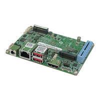
IEI Technology HYPER-EHL User Manual (114 pages)
Pico-ITX SBC Supports Intel® Celeron® J6412/N6210 on-board SoC with 4GB LPDDR4x, HDMI, iDPM, M.2, 2.5GbE LAN, PCIe x4 Slot, COM, iSATA 6Gb/s, USB 3.2 Gen 2, and RoHS
Brand:
IEI Technology
| Category:
Computer Hardware
| Size: 6 MB
Table of Contents
Table of Contents
5
Introduction
12
Ntroduction
13
Figure 1-1: HYPER-EHL
13
Features
14
Connectors
15
Figure 1-2: Connectors
15
Dimensions
16
Figure 1-3: HYPER-EHL Dimensions (MM)
16
Data Flow
17
Figure 1-4: Data Flow Diagram
17
Technical Specifications
18
Table 1-1: HYPER-EHL Specifications
19
Packing List
20
Anti-Static Precautions
21
Unpacking Precautions
21
Packing List
22
Table 2-1: Packing List
22
Optional Items
23
Table 2-2: Optional Items
24
Connectors
25
Peripheral Interface Connectors
26
HYPER-EHL Layout
26
Figure 3-1: Peripheral Interface Connectors
26
External Interface Panel Connectors
27
Table 3-1: Peripheral Interface Connectors
27
Table 3-2: Rear Panel Connectors
27
Internal Peripheral Connectors
28
Battery Connector
28
Figure 3-2: Battery Connector Location
29
Table 3-3: Battery Connector Pinouts
29
AT/ATX Power Mode Setting
30
Figure 3-3: AT/ATX Power Mode Switch Location
30
Table 3-4: AT/ATX Power Mode Switch Settings
30
Digital I/O Connector
31
Figure 3-4: Digital I/O Connector Location
31
Table 3-5: Digital I/O Connector Pinouts
31
Clear CMOS Button
32
Figure 3-5: Clear CMOS Jumper Location
32
Table 3-6: Clear CMOS Jumper Pinouts
32
I 2 C Connector
33
Figure 3-6: I 2 C Connector Location
33
Table 3-7: I² C Connector Pinouts
33
Internal USB 2.0 Connectors
34
Figure 3-7: Internal USB 2.0 Connector Location
34
Table 3-8: Internal USB 2.0 Connector Pinouts
34
M-Key Slot
35
Figure 3-8: M.2 M-Key Slot Location
35
Table 3-9: M.2 M-Key Connector Pinouts
36
IEI Idpm Slot
37
Figure 3-9: Idpm Slot Location
37
Table 3-10: Idpm Connector Pinouts
38
Pcie X4 Slot
39
Power Button Connector
39
Figure 3-10: Pcie X4 Slot Location
39
Reset Button Connector
40
Figure 3-11: Power Button Connector Location
40
Figure 3-12: Reset Button Connector Location
40
Isata 6Gb/S Connectors
41
Figure 3-13: Isata Connector Location
41
Table 3-11: Isata Connector Pinouts
41
RS-232/422/485 Serial Port Connector
42
Figure 3-14: RS-232/422/485 Connector Location
42
Table 3-12: RS-232/422/485 Connector Pinouts
42
Buzzer Connector
43
Figure 3-15: Buzzer Connector Location
43
Table 3-13: Buzzer Connector Pinouts
43
Flash SPI ROM Connector
44
Figure 3-16: Flash SPI ROM Connector Location
44
Table 3-14: Flash SPI ROM Connector Pinouts
44
External Peripheral Interface Connector Panel
45
External 12V DC Input Jack
45
Figure 3-17: External Peripheral Interface Connector
45
Figure 3-18: External 12V DC Input Jack Location
45
Table 3-15: External 12V DC Input Jack Pinouts
45
External 2.5Gbe RJ-45 Connector
46
Figure 3-19: LAN Connector
46
Table 3-16: 2.5Gbe RJ-45 Connector Pinouts
46
Table 3-17: LAN LED Pinouts
46
External HDMI Combo Connector
47
Figure 3-20: External HDMI Connector Location
47
Table 3-18: External HDMI Connector Pinouts
47
External Dual USB 3.2 Gen2 10Gb/S Connector
48
Figure 3-21: External Dual USB 3.2 Gen2 Connectors Location
48
Table 3-19: External Dual USB 3.2 Gen2 Connectors Pinouts
48
Installation
49
Anti-Static Precautions
50
Installation Considerations
50
Module Installation
51
Figure 4-1: Inserting the M.2 Module into the Slot at an Angle
52
Figure 4-2: Securing the M.2 Module
52
Figure 4-3: Press the Retainer
53
Figure 4-4: Aligning the M.2 Module with the Retainer
53
Riser Card Installation
54
Figure 4-5: Securing the M.2 Module
54
The Inwards-Facing Riser Card
55
Figure 4-6:Inwards Riser Card Installation Example (P/N: HPR-R2S-R10)
55
The Outwards-Facing Riser Card
56
Figure 4-7: Inwards Riser Card Installation Example (P/N: HPR-R4S-R10)
56
Figure 4-8: Outwards Riser Card Installation Example (P/N: NWR-L2S-R10)
56
Figure 4-9: Outwards Riser Card Installation Example (P/N: NWR-L4S-R10)
57
Software Installation
58
Driver Download
58
Figure 4-10: IEI Resource Download Center
58
Bios
60
Introduction
61
Starting Setup
61
Figure 5-1: BIOS Starting Menu
61
Using Setup
62
Keyboard Navigation
62
Table 5-1: BIOS Navigation Keys
62
Touch Navigation
63
Table 5-2: BIOS On-Screen Navigation Keys
63
Getting Help
64
Unable to Reboot after Configuration Changes
64
BIOS Menu Bar
64
Main
65
Advanced
68
BIOS Menu 4: Advanced
68
CPU Configuration
69
Trusted Computing
73
BIOS Menu 8: PCH-FW Configuration
73
IT5571 Super IO Configuration
74
BIOS Menu 9: IT5571 Super IO Configuration
74
Serial Port 1 Configuration
75
BIOS Menu 10: Serial Port 1 Configuration Menu
75
IT5571 H/W Monitor
76
BIOS Menu 11: IT5571 H/W Monitor
76
RTC Wake Settings
77
Serial Port Console Redirection
79
BIOS Menu 14: Serial Port Console Redirection
79
Console Redirection Settings
80
BIOS Menu 15: COM Console Redirection Settings
80
Nvme Configuration
82
BIOS Menu 16: Nvme Configuration
82
Chipset
83
BIOS Menu 17: Chipset
83
System Agent (SA) Configuration
84
BIOS Menu 18: System Agent (SA) Configuration
84
Memory Configuration
85
BIOS Menu 19: Memory Configuration
85
Graphics Configuration
86
BIOS Menu 20: Graphics Configuration
86
BIOS Menu 21: LCD Control
88
PCH-IO Configuration
89
BIOS Menu 22: PCH-IO Configuration
89
PCI Express Configuration
90
BIOS Menu 23: PCI Express Configuration
90
Pcie Root Port Setting
91
BIOS Menu 24: Pcie Slot Configuration Submenu
91
SATA Configuration
92
BIOS Menu 25: SATA Configuration
92
Security
94
Boot
96
Boot Configuration
96
BIOS Menu 28: Boot
96
Boot Option Priorities
97
Save & Exit
98
BIOS Menu 29: Save & Exit
98
A Regulatory Compliance
100
B Product Disposal
102
CBIOS Options
104
D Watchdog Timer
107
E Error Beep Code
110
Pei Beep Codes
111
Dxe Beep Codes
111
F Hazardous Materials Disclosure
112
Rohs II Directive (2015/863/EU)
113
China Rohs
114
Advertisement
IEI Technology HYPER-EHL Quick Installation Manual (12 pages)
Pico-ITX SBC Supports Intel® Celeron® J6412/N6210 on-board SoC with 4GB LPDDR4x, HDMI, iDPM, 2.5GbE LAN, M.2, PCIe x4 Slot, iSATA 6Gb/s, COM, USB 3.2 Gen 2, and RoHS
Brand:
IEI Technology
| Category:
Computer Hardware
| Size: 0 MB
Advertisement
Related Products
IEI Technology HYPER-BT-E38 1 Series
IEI Technology HYPER-BT-J19001 HYPER-BT-N29301
IEI Technology HYPER-BT-N28071
IEI Technology HYPER-BT
IEI Technology HYPER-BW
IEI Technology HYPER-AL series
IEI Technology HYPER-AL
IEI Technology HYPER-RK3566
IEI Technology HYPER-RK39
IEI Technology HYPER-KBN-2171-R10
IEI Technology Categories
Motherboard
Touch Panel
Computer Hardware
Single board computers
Desktop
More IEI Technology Manuals
Login
Sign In
OR
Sign in with Facebook
Sign in with Google
Upload manual
Upload from disk
Upload from URL