Sign In
Upload
Manuals
Brands
IEI Technology Manuals
Single board computers
167320
IEI Technology 167320 Manuals
Manuals and User Guides for IEI Technology 167320. We have
1
IEI Technology 167320 manual available for free PDF download: User Manual
IEI Technology 167320 User Manual (79 pages)
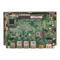
3.5" SBC with Intel 10nm Jasper Lake Celeron N5105 Processor with Dual Displays, DDR4, Triple Intel 2.5 GbE, USB3.2, M.2, SATA, COM, SoC, RoHS
Brand:
IEI Technology
| Category:
Single board computers
| Size: 8.88 MB
Table of Contents
Table of Contents
5
Introduction
13
Ntroduction
14
Figure 1-1: WAFER-JL-N5105
14
Features
15
Connectors
15
Figure 1-2: Connectors
15
Dimensions
16
Figure 1-3: Dimensions (MM)
16
Data Flow
17
Figure 1-4: Data Flow Diagram
17
Technical Specifications
18
Table 1-1: Technical Specifications
19
Unpacking
20
Anti-Static Precautions
21
Unpacking Precautions
21
Packing List
22
Table 2-1: Packing List
22
Optional Items
23
Table 2-2: Optional Items
23
Connectors
24
Peripheral Interface Connectors
25
WAFER-JL-N5105 Layout
25
Figure 3-1: Connector and Jumper Locations
25
Table 3-1: Peripheral Interface Connectors
26
External Interface Panel Connectors
27
Internal Peripheral Connectors
27
Clear CMOS Button
27
Table 3-2: Rear Panel Connectors
27
Figure 3-2: Clear CMOS Location
28
Table 3-3: Clear CMOS Pinouts
28
AT/ATX Power Mode Setting
29
ME Override Setting Jumper
29
Figure 3-3: AT/ATX Power Mode Switch Locations
29
Table 3-4: AT/ATX Power Mode Switch Pinouts
29
Figure 3-4: ME Override Setting Jumper Locations
30
Table 3-5: ME Override Setting Jumper Pinouts
30
Audio Connector
31
Figure 3-5: Audio Connector Location
31
Table 3-6: Audio Connector Pinouts
31
ATX 12V Power Connector
32
Digital I/O Connector
32
Figure 3-6: ATX 12V Power Connector Location
32
Table 3-7: ATX 12V Power Connector Pinouts
32
Figure 3-7: Digital I/O Connector Location
33
Table 3-8: Digital I/O Connector Pinouts
33
Fan Connector
34
Figure 3-8: Fan Connector Location
34
Table 3-9: Fan Connector Pinouts
34
Power LED & HDD LED Connector
35
Figure 3-9: Power LED & HDD LED Connector Location
35
Table 3-10: Power LED & HDD LED Connector Pinouts
35
LAN LED Connectors
36
Figure 3-10: LAN LED Connector Locations
36
Table 3-11: LAN1 LED Connector Pinouts
36
Table 3-12: LAN2 LED Connector Pinouts
36
Battery Connector
37
Table 3-13: LAN3 LED Connector Pinouts
37
Figure 3-11: Battery Connector Location
38
Table 3-14: Battery Connector Pinouts
38
Power Button Connector
39
Figure 3-12: Power Button Connector Location
39
Table 3-15: Power Button Connector Pinouts
39
Reset Button Connector
40
Figure 3-13: Reset Button Connector Location
40
Table 3-16: Reset Button Connector Pinouts
40
RS-232 Serial Port Connector
41
Figure 3-14: RS-232 Serial Port Connector Location
41
Table 3-17: RS-232 Serial Port Connector Pinouts
41
SATA 6Gb/S Drive Connector
42
Figure 3-15: SATA 6Gb/S Drive Connectors Location
42
Table 3-18: SATA 6Gb/S Drive Connectors Pinouts
42
SATA Power Connector
43
Figure 3-16: SATA Power Connector Location
43
Table 3-19: SATA Power Connector Pinouts
43
Smbus/I C Connector
44
Figure 3-17: Smbus Connector Location
44
Table 3-20: Smbus Connector Pinouts
44
SPI Flash Connector
45
Figure 3-18: SPI Flash Connector Location
45
Table 3-21: SPI Flash Connector Pinouts
45
USB 2.0 Connector
46
Figure 3-19: USB Connector Location
46
Table 3-22: USB Connector Pinouts
46
Slot, B-Key
47
Figure 3-20: M.2 B Key Slot Location
47
Table 3-23: M. 2 B Key Slot Pinouts
48
Slot, A-Key
49
Figure 3-21: M.2 A-Key Slot Location
49
Table 3-24: M.2 A-Key Slot Pinouts
50
SIM Slot
51
Figure 3-22: SIM Slot Location
51
Table 3-25: SIM Slot Pinouts
51
DDR4 SO-DIMM Socket
52
Figure 3-23: DDR4 SO-DIMM Socket Location
52
External Peripheral Interface Connector Panel
53
Figure 3-24: External Peripheral Interface Connector
53
External 2.5Gbe RJ-45 Connectors
54
Figure 3-25: LAN Location
54
Figure 3-26: LAN LED Location
54
Table 3-26: LAN Pinouts
54
External USB 3.2 Gen 2X1 Type-A
55
Figure 3-27: USB 3.2 Gen 2 Port Location
55
Table 3-27: LAN LED Pinouts
55
External Displayport Connector
56
Table 3-28: USB 3.2 Gen 2 Port Pinouts
56
External Interface Panel Connectors
57
Figure 3-28: External Displayport Connector Location
57
Figure 3-29: HDMI Connector Pinout Locations
57
Installation
58
Anti-Static Precautions
59
Installation Considerations
59
So-DIMM Installation
61
Figure 4-1: SO-DIMM Installation
61
Module Installation
62
Figure 4-2: Inserting the M.2 Module into the Slot at an Angle
62
Figure 4-3: Securing the M.2 Module
62
Chassis Installation
63
Heat Spreader
63
Figure 4-4: Heat Sink Retention Screws
63
Motherboard Installation
64
Figure 4-5: Active Cooling
64
Figure 4-6: Passive Cooling
64
Figure 4-7: DRPC-W-JL-R10
64
Figure 4-8: DRPC-W-JL-R10 with Extra Fan Cooling
64
Internal Peripheral Device Connections
65
AT Power Connection
65
Figure 4-9: Motherboard Installation Example
65
Figure 4-10: Power Cable to Motherboard Connection
66
Channel Audio Kit Installation
67
Figure 4-11: Connect Power Cable to Power Supply
67
RS-232 Cable Connection
68
Figure 4-12: 7.1 Channel Audio Kit
68
SATA Drive Connection
69
Figure 4-13: Single RS-232 Cable Installation
69
Figure 4-14: SATA Drive Cable Connection
70
Software Drivers
71
Available Drivers
72
Driver Download
72
Figure 5-1: IEI Resource Download Center
72
A Regulatory Compliance
74
C Product Disposal
76
D Error Beep Code
78
Pei Beep Codes
79
Dxe Beep Codes
79
Advertisement
Advertisement
Related Products
IEI Technology iSignager 10.4
IEI Technology PPC-F 15B-BTi-J1/2G/PC-R10
IEI Technology PPC-F 17B-BTi-J1/2G/PC-R10
IEI Technology AESQ170-969
IEI Technology DRPC-124-EHL Series
IEI Technology DRPC-124-EHL-JC-R10
IEI Technology DRPC-230-ULT5-C/8G/S
IEI Technology gKINO-DMF Series
IEI Technology gKINO-R1000 Series
IEI Technology gKINO-R1505G
IEI Technology Categories
Motherboard
Touch Panel
Computer Hardware
Single board computers
Desktop
More IEI Technology Manuals
Login
Sign In
OR
Sign in with Facebook
Sign in with Google
Upload manual
Upload from disk
Upload from URL