Sign In
Upload
Manuals
Brands
IEI Technology Manuals
Touch Panel
AFL3-W15B-H81
IEI Technology AFL3-W15B-H81 Manuals
Manuals and User Guides for IEI Technology AFL3-W15B-H81. We have
1
IEI Technology AFL3-W15B-H81 manual available for free PDF download: User Manual
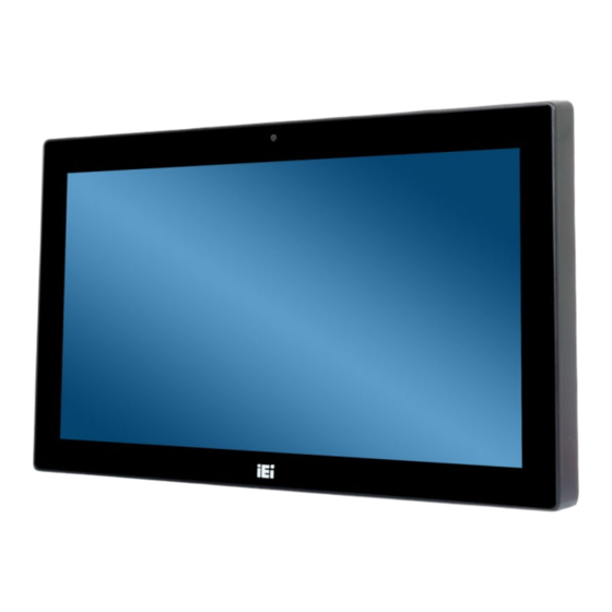
IEI Technology AFL3-W15B-H81 User Manual (138 pages)
flat bezel panel PC with Intel H81 chipset, touchscreen, dual GbE LAN, Wi-Fi 802.11a/b/g/n/ac, dual USB 3.0, 2-megapixel camera, UP 64 compliant front panel
Brand:
IEI Technology
| Category:
Touch Panel
| Size: 5 MB
Table of Contents
Table of Contents
5
1 Introduction
15
Overview
16
Model Variations
16
Figure 1-1: AFL3-W15B-H81 Flat Bezel Panel PC
16
Features
17
Table 1-1: Model Variations
17
Front Panel
18
Figure 1-2: Front View
18
Rear Panel
19
Bottom Panel
19
Figure 1-3: Rear View
19
System Specifications
20
Figure 1-4: Bottom Panel
20
Table 1-2: System Specifications
22
Dimensions
23
Figure 1-5: AFL3-W15B-H81 Dimensions (MM)
23
Figure 1-6: AFL3-W15B-H81 with AFL3-2D-R10 Dimensions (MM)
24
2 Unpacking
25
Unpacking
26
Packing List
27
Optional Items
28
3 Installation
31
Anti-Static Precautions
32
Installation Precautions
32
Installation and Configuration Steps
33
Removing the
33
Figure 3-1: AFL3-W15B-H81 Back Cover Retention Screws
33
Hdd Installation
34
Figure 3-2: Removing the Back Cover
34
Figure 3-3: HDD Bracket Retention Screws
35
Figure 3-4: HDD Retention Screws
35
Msata Module Installation
36
Figure 3-5: HDD Installation
36
Figure 3-6: Msata Slot Location
36
Com1 Db-9 Serial Port Pin 9 Selection
37
Figure 3-7: Msata Module Installation
37
Table 3-1: COM1 DB-9 Serial Port Pin 9 Setting Jumper Settings
37
Or Rs-422/485 Selection for Com1 Serial Port
38
Figure 3-8: COM1 DB-9 Serial Port Pin 9 Setting Jumper Location
38
Table 3-2: COM1_SEL1 Jumper Settings
38
Or Rs-485 Selection for Com1 Serial Port
39
Figure 3-9: COM1_SEL1 Jumper Location
39
Table 3-3: JP6 Jumper Settings
39
Clear Cmos
40
Figure 3-10: JP6 Jumper Location
40
Table 3-4: Clear CMOS Jumper Settings
40
At/Atx Mode Selection
41
Figure 3-11: Clear CMOS Jumper Location
41
Figure 3-12: AT/ATX Switch Location
41
AT Power Mode
42
ATX Power Mode
42
Mounting the System
42
Figure 3-13: Wall-Mounting Bracket
43
Wall Mounting
43
Figure 3-14: Chassis Support Screws
45
Figure 3-15: Secure the Panel PC
45
Figure 3-16: AFL3-W15B-H81 Cutout Dimensions
46
Panel Mounting
46
Figure 3-17: Panel Mounting Kit Installation
47
Cabinet and Rack Installation
48
Figure 3-18: Securing Panel Mounting Brackets
48
Figure 3-19: Rack/Cabinet Bracket Installation
49
Figure 3-20: Rack Mounting Kit Installation
50
Figure 3-21: Securing Rack Mounting Brackets
51
Figure 3-22: Install into a Rack/Cabinet
51
Arm Mounting
52
Figure 3-23: Arm Mounting Retention Screw Holes
53
Figure 3-24: Arm Mounting
53
Figure 3-25: Stand Mounting (Stand-A/Bxx)
54
Stand Mounting
54
Powering on the System
55
Figure 3-26: Powering on the System
55
Reset the System
56
Software Installation
56
Figure 3-27: Reset Button Location
56
Calibrating the Resistive Type Touchscreen
57
Figure 3-28: Keypad AP
57
Figure 3-29: Select Control Panel
57
Keypad AP
57
Figure 3-30: Touchscreen Control Panel
58
Figure 3-31: Select Calibration Type
58
Figure 3-32: Calibration Window
59
4 Bios Setup
60
Introduction
61
Starting Setup
61
Using Setup
61
BIOS Menu Bar
62
Getting Help
62
Table 4-1: BIOS Navigation Keys
62
Unable to Reboot after Configuration Changes
62
Main
63
BIOS Menu 1: Main
63
Advanced
64
BIOS Menu 2: Advanced
64
System Date [XX/XX/XX]
64
System Time [XX:XX:XX]
64
ACPI Settings
65
BIOS Menu 3: ACPI Settings
65
ACPI Sleep State [S1 Only (CPU Stop Clock)]
65
RTC Wake Settings
66
BIOS Menu 4: RTC Wake Settings
66
Wake System with Fixed Time [Disabled]
66
CPU Configuration
67
BIOS Menu 5: CPU Configuration
67
Hyper-Threading [Enabled]
67
Active Processor Cores [All]
68
Intel Virtualization Technology [Disabled]
68
EIST [Enabled]
68
SATA Configuration
69
BIOS Menu 6: SATA Configuration
69
SATA Controller(S) [Enabled]
69
SATA Mode Selection [IDE]
69
Intel(R) Rapid Start Technology
70
BIOS Menu 7: Intel(R) Rapid Start Technology
70
Intel(R) Rapid Start Technology [Disabled]
70
USB Configuration
71
BIOS Menu 8: USB Configuration
71
USB Devices
71
Legacy USB Support [Enabled]
71
F81866 Super IO Configuration
72
BIOS Menu 9: F81866 Super IO Configuration
72
Serial Port 1 Configuration
73
Serial Port N Configuration
73
BIOS Menu 10: Serial Port N Configuration Menu
73
Serial Port [Enabled]
73
Change Settings [Auto]
73
Serial Port 2 Configuration
74
Device Mode [RS232]
74
Serial Port [Enabled]
74
Change Settings [Auto]
74
Touch Configuration
75
Serial Port [Enabled]
75
Change Settings [Auto]
75
F81866 H/W Monitor
76
BIOS Menu 11: F81866 H/W Monitor
76
PC Health Status
76
Smart Fan Mode Configuration
77
BIOS Menu 12: Smart Fan Mode Configuration
77
CPU_FAN1 Smart Fan Control/Sys_Fan1 Smart Fan Control [Auto Duty-Cycle Mode]
77
Serial Port Console Redirection
78
BIOS Menu 13: Serial Port Console Redirection
78
CPU Temperature 1/2/3/4
78
System Temperature 1/2/3/4
78
Console Redirection Settings
79
BIOS Menu 14: Console Redirection Settings
79
Console Redirection [Disabled]
79
Terminal Type [ANSI]
79
Bits Per Second [115200]
80
Data Bits [8]
80
Parity [None]
80
Iei Feature
81
BIOS Menu 15: Iei Feature
81
Stop Bits [1]
81
Auto Recovery Function [Disabled]
81
Chipset
82
BIOS Menu 16: Chipset
82
PCH-IO Configuration
83
BIOS Menu 17: PCH-IO Configuration
83
Restore AC Power Loss [Last State]
83
M_PCIE1/M-SATA and M_PCIE2
84
PCI Express Configuration
84
BIOS Menu 18: PCI Express Configuration
84
BIOS Menu 19: M_PCIE1/M-SATA and M_PCIE2 Configuration Menu
84
Pcie Speed [Auto]
85
Detect Non-Compliance Device [Disbled]
85
PCH Azalia Configuration
86
BIOS Menu 20: PCH Azalia Configuration
86
Azalia (HD Audio) [Enabled]
86
System Agent (SA) Configuration
87
BIOS Menu 21: System Agent (SA) Configuration
87
VT-D [Disabled]
87
Graphics Configuration
88
BIOS Menu 22: Graphics Configuration
88
Primary Display [Auto]
88
DVMT Pre-Allocated [256M]
88
LCD Control
89
BIOS Menu 23: LCD Control
89
DVMT Total Gfx Mem [MAX]
89
Memory Configuration
90
BIOS Menu 24: Memory Configuration
90
Primary IGFX Boot Display [VBIOS Default]
90
Boot
91
BIOS Menu 25: Boot
91
Bootup Numlock State [On]
91
Quiet Boot [Enabled]
92
Option ROM Messages [Force BIOS]
92
Launch PXE Oprom [Disabled]
92
UEFI Boot [Disabled]
92
Security
93
Save & Exit
93
BIOS Menu 26: Security
93
Administrator Password
93
User Password
93
BIOS Menu 27: Save & Exit
94
Save Changes and Reset
94
Discard Changes and Reset
94
Restore Defaults
94
Save as User Defaults
94
Restore User Defaults
94
5 System Maintenance
95
System Maintenance Introduction
96
Anti-Static Precautions
96
Turn off the Power
97
So-DIMM Replacement
97
Figure 5-1: SO-DIMM Module Locations
97
Wlan Card Replacement
98
Figure 5-2: SO-DIMM Module Installation
98
Figure 5-3: WLAN Card Location
99
Figure 5-4: Releasing the WLAN Card
99
Reinstalling the Cover
100
Figure 5-5: Removing the WLAN Card
100
6 Interface Connectors
101
Peripheral Interface Connectors
102
Figure 6-1: Main Board Layout Diagram (Front Side)
102
Internal Peripheral Connectors
103
Figure 6-2: Main Board Layout Diagram (Solder Side)
103
Battery Connector (BAT1)
104
Table 6-1: Peripheral Interface Connectors
104
Table 6-2: Battery Connector (BAT1) Pinouts
104
Digital I/O Connector (DIO1)
105
Fan Connector (CPU_FAN1)
105
Fan Connector (SYS_FAN1)
105
Hotkey Connector (HOTKEY_CN1)
105
Table 6-3: Digital I/O Connector (DIO1) Pinouts
105
Table 6-4: Fan Connector (CPU_FAN1) Pinouts
105
Table 6-5: Fan Connector (SYS_FAN1) Pinouts
105
Inverter Connector (INVERTER1)
106
LVDS Connector (LVDS1)
106
Table 6-6: Hotkey Connector (HOTKEY_CN1) Pinouts
106
Table 6-7: Inverter Connector (INVERTER1) Pinouts
106
MCU Firmware Connector (JP8)
107
Microphone Connector (DMIC1)
107
Pcie Mini/Msata Slot (M_PCIE1)
107
Table 6-10: Microphone Connector (DMIC1) Pinouts
107
Table 6-8: LVDS Connector (LVDS1) Pinouts
107
Table 6-9: MCU Firmware Connector (JP8) Pinouts
107
Pcie Mini Slot (M_PCIE2)
108
Table 6-11: Pcie Mini/Msata Slot (M_PCIE1) Pinouts
108
Power Button Connector (PW_BT1)
109
Power LED Connector (PW_LED1)
109
Table 6-12: Pcie Mini Slot (M_PCIE2) Pinouts
109
Table 6-13: Power LED Connector (PW_LED1) Pinouts
109
Table 6-14: Power Button Connector (PW_BT1) Pinouts
109
SATA Signal and Power Connector (SATA1)
110
Smbus Connector (CN1)
110
Table 6-15: SATA Signal and Power Connector (SATA1) Pinouts
110
Table 6-16: Smbus Connector (CN1) Pinouts
110
Speaker Connector (AUDIO_OUT1)
111
SPI Flash Connector (JSPI1)
111
Table 6-17: Speaker Connector (AUDIO_OUT1) Pinouts
111
Table 6-18: SPI Flash Connector (JSPI1) Pinouts
111
Table 6-19: TTL Serial Connector (NFC_COM4) Pinouts
111
TTL Serial Connector (NFC_COM4)
111
Table 6-20: USB Connector for Barcode Reader (BR_USB1) Pinouts
112
Table 6-21: USB Connector for Bluetooth (BT_USB1) Pinouts
112
Table 6-22: USB Connector for Camera (CAM_USB1) Pinouts
112
USB Connector for Barcode Reader (BR_USB1)
112
USB Connector for Bluetooth (BT_USB1)
112
USB Connector for Camera (CAM_USB1)
112
Table 6-23: USB Connector for NFC (NFC_USB1) Pinouts
113
Table 6-24: USB Connector for Touchscreen (TOUCH_USB1) Pinouts
113
Table 6-25: VGA Connector (VGA_CON1) Pinouts
113
USB Connector for NFC (NFC_USB1)
113
USB Connector for Touchscreen (TOUCH_USB1)
113
VGA Connector (VGA_CON1)
113
External Interface Panel Connectors
114
Gbe Connectors (LAN1 & LAN2)
114
Table 6-26: Rear Panel Connectors
114
Table 6-27: Gbe Connectors (LAN1 & LAN2) Pinouts
114
HDMI Connector (HDMI1)
115
Power Connector (PWR1)
115
Serial Port (COM2)
115
Table 6-28: HDMI Connector (HDMI1) Pinouts
115
Table 6-29: Power Connector (PWR1) Pinouts
115
Table 6-30: RS-232 DB-9 Serial Port (COM2) Pinouts
115
RS-232/422/485 DB-9 Serial Port (COM1)
116
Table 6-31: RS-232/422/485 DB-9 Serial Port (COM1) Pinouts
116
Table 6-32: USB 2.0 Connectors (USB20_CN1) Pinouts
116
Table 6-33: USB 2.0 Connectors (USB20_CN2) Pinouts
116
USB 2.0 Connectors (USB20_CN1)
116
USB 2.0 Connectors (USB20_CN2)
116
USB 3.0 Connectors (USB_CON1)
116
Preconfigured Jumper Settings
117
Flash Descriptor Security Override Jumper (J_FLASH1)
117
Table 6-34: USB 3.0 Connectors (USB_CON1) Pinouts
117
Table 6-35: Preconfigured Jumpers
117
Table 6-36: Flash Descriptor Security Override Jumper (J_FLASH1) Settings
117
LVDS Panel Voltage Selection Jumper (J_VLVDS1)
118
Table 6-37: LVDS Panel Voltage Selection Jumper (J_VLVDS1) Settings
118
A Regulatory Compliance
119
B Safety Precautions
124
Safety Precautions
125
B.1 S Afety P Recautions
125
General Safety Precautions
125
Anti-Static Precautions
126
Product Disposal
127
Maintenance and Cleaning Precautions
128
B.2 M Aintenance and C Leaning P Recautions
128
Cleaning Tools
128
Maintenance and Cleaning
128
C Bios Menu Options
130
Appendix C
131
D Watchdog Timer
133
E Hazardous Materials Disclosure
136
Advertisement
Advertisement
Related Products
IEI Technology AFL3-W15C
IEI Technology AFL3-W15A-AL
IEI Technology AFL3-W15C-ULT5-P-PC-4G
IEI Technology AFL3-W15C-ULT3
IEI Technology AFL3W19C-ULT3
IEI Technology AFL3-W10A-AL
IEI Technology AFL3-W10A
IEI Technology AFL3-W12A
IEI Technology AFL3-W12A-BT
IEI Technology AFL3-W10A-BT
IEI Technology Categories
Motherboard
Touch Panel
Computer Hardware
Single board computers
Desktop
More IEI Technology Manuals
Login
Sign In
OR
Sign in with Facebook
Sign in with Google
Upload manual
Upload from disk
Upload from URL