Sign In
Upload
Manuals
Brands
Honeywell Manuals
Security System
Notifier NFS2-640/E
Honeywell Notifier NFS2-640/E Manuals
Manuals and User Guides for Honeywell Notifier NFS2-640/E. We have
4
Honeywell Notifier NFS2-640/E manuals available for free PDF download: Operation Manual, Programming Manual, Manual, Operating Instructions
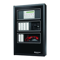
Honeywell Notifier NFS2-640/E Operation Manual (477 pages)
Fire Alarm Control Panel
Brand:
Honeywell
| Category:
Control Panel
| Size: 28 MB
Table of Contents
Installation Precautions
6
FCC Warning
6
Software Downloads
7
Documentation Feedback
7
Table of Contents
8
Section 1: General Information
11
UL 864 Compliance
11
About this Manual
11
1: Cautions and Warnings
11
2: Typographic Conventions
11
3: Supplemental Information
12
4: Shortcuts to Operating Functions
14
Introduction to the Control Panel
14
Section 2: Use of the Controls
15
Introduction
15
System Status Indicator Leds
15
Control Keys
16
1: Acknowledge/Scroll Display
16
2: Signal Silence
17
3: System Reset
17
4: Drill
17
5: Lamp Test
18
Programming Keypad
18
Section 3: Operation of the Control Panel
21
Normal Mode of Operation
21
Fire Alarm Mode of Operation
21
1: How the Control Panel Indicates a Fire Alarm
21
2: How to Respond to a Fire Alarm
22
3: Interpreting Fire Alarm Type Codes
22
Monitor Modules
22
Mass Notification Mode of Operation
24
1: How the Control Panel Indicates a Mass Notification Alarm
24
2: How to Respond to an MN Alarm
25
3: How the Control Panel Indicates a Mass Notification Supervisory
25
4: How to Respond to an MN Supervisory
26
5: How the Control Panel Indicates a Mass Notification Trouble
26
6: How to Respond to an MN Trouble
26
7: Interpreting MN Type Codes
28
System Trouble Mode of Operation
28
1: How the Control Panel Indicates a System Trouble
28
2: How to Respond to a System Trouble
29
Security Alarm Mode of Operation
30
1: How the Control Panel Indicates a Security Alarm
30
2: How to Respond to a Security Alarm
30
3: Interpreting Security Type Codes
31
Active Supervisory Signal Mode of Operation
31
1: How the Control Panel Indicates an Active Supervisory
31
2: How to Respond to an Active Supervisory
32
3: How to Interpret Supervisory Type Codes
32
Pre-Alarm Warning Mode of Operation
34
1: How the Control Panel Indicates a Pre-Alarm Warning
34
2: How to Respond to a Pre-Alarm Warning
34
Disabled Points Mode of Operation
35
Non-Alarm Mode of Operation
35
1: Purpose of Non-Alarm Points
35
2: How the Control Panel Indicates an Active Fire Control
36
3: How the Control Panel Indicates an Active Non-Fire Point
36
CO Alarm Mode of Operation
36
1: How the Control Panel Indicates a CO Alarm
36
2: How to Respond to a CO Alarm
37
3: Interpreting CO Alarm/Supervisory Type Codes
38
Active Trouble Monitor Mode of Operation
38
1: How the Control Panel Indicates an Active Trouble Monitor
38
2: How to Respond to an Active Trouble Monitor
39
Output Circuit Trouble Mode of Operation
39
1: Overview
39
2: How the Control Panel Indicates a NAC Trouble
40
3: How the Control Panel Indicates a Control/Relay Trouble
41
4: How to Respond to a NAC or Control/Relay Trouble
41
Operation of Special System Timers
41
1: What Are System Timers
41
2: How to View System Timer Selections
41
3: How System Timers Work
42
Auto Silence Timer
42
Silence Inhibit Timer
42
Waterflow Circuit Operation
43
Style 6 and Style 7 Operation
43
Section 4: Read Status Operation
44
Introduction
44
What Is Read Status
44
1: Quick Reference Key Sequences
44
Entering Read Status
44
Viewing and Printing a Read Status
45
2: How to View Read Status for Event and Alarm History
55
3: How to Print Points, Event and Alarm History
56
4: How to View and Print Hidden Event and Alarm History
58
Appendix A: Special Zone Operation
59
A.2: Releasing Zones (R0-R9)
59
A.2.1: Purpose of Releasing Zones
59
A.3: Time, Date, and Holiday Functions
59
A.4: NAC Coding
59
How Releasing Zones Operate
60
NAC Coding
64
A.4.1: Overview of Coding
64
A.4.2: How to View Coding (F8) Selections
65
A.4.3: How to Respond to an Alarm with Coding
65
A.5: Presignal and Positive Alarm Sequence (PAS) Operation
65
A.5.2: What Is Presignal and PAS
65
A.5.3: How to View Presignal and PAS Selections
67
A.5.4: How to Respond to an Alarm with Presignal Delay Timer (no PAS)
67
A.5.5: How to Respond to an Alarm with Presignal Delay Timer (PAS Selected)
68
Appendix B: Intelligent Detector Functions
69
Appendix C: Remote Terminal Access
70
C.1: General Description
70
C.2: Operating Modes
70
C.2.1: Local Terminal Mode (Loct)
70
Local Monitor Mode (Locm)
71
C.2.3: Remote Terminal Mode (Remt)
71
C.3: Using the CRT-2 for Read Status
72
C.3.2: Accessing Read Status Options
72
Read Point
73
C.3.4: Display Devices in Alarm or Trouble
73
C.3.5: Display All Programmed Points
74
C.3.6: Step-Through History
74
C.3.7: View All History
74
C.3.8: Step-Through Alarm History
74
C.3.9: View All Alarm History
74
C.4: Using the CRT-2 for Alter Status
75
C.4.2: Accessing Alter Status Options
75
C.4.3: Enable or Disable Detectors, Modules or Zones
76
C.4.4: Change Alarm and Pre-Alarm Levels
76
C.4.5: Clear Verification Counter
77
C.4.6: Clear the Entire History Buffer
77
C.4.7: Set the Pre-Alarm for Alert or Action
77
Appendix D: Point and System Troubles Lists
79
D.1: Point (Device) Troubles
79
D.2: System Troubles
80
Index
83
Manufacturer Warranties and Limitation of Liability
86
Installation Precautions
90
FCC Warning
90
Software Downloads
91
Documentation Feedback
91
Section 1: about this Manual
95
Standards and Specifications
95
UL 864 Ninth Edition Compliance
95
Programming Features Subject to AHJ Approval
96
Related Documentation
96
Notes, Cautions, and Warnings
97
Conventions
98
Section 2: Overview
99
General Description
99
2: Compatibility with NOTI•FIRE•NET™ Panel Nodes
100
NCA-2 and Displayless Panels
101
NCA-2 / NFS2-640 Standalone Application
102
NCA-2 Board Layout
103
2: EIA-232 Optional Devices
104
3: EIA-485 Annunciator Devices
104
4: Other Optional Devices
106
Section 3: Installation
107
Preparing for Installation
107
Installation Checklist
108
ABS-2D, ABS-4D Cabinets
110
CHS-M3 Chassis
111
Mounting Chassis in Backbox
112
3: Memory-Backup Battery
112
4: Option Boards
113
Mounting Procedures
113
CA-2 Chassis Assembly
114
NCA-2 / NFS2-640 Standalone
115
Retrofits
115
Form-C Relays on the NCA-2
115
Network Communications Module
116
Central Station Fire Alarm System Canadian Requirements
117
Connecting Power Sources and Outputs
118
2: Connecting the Power Supply
118
3: Checking AC Power
119
4: Power Considerations When Servicing
120
UL Power-Limited Wiring Requirements
120
Installing Printers
121
1: Printer Installation Sequence
122
Configuring the Printer
123
PRN Printer Settings
123
Keltron Printer VS4095/5 Settings
124
Connecting a PC for Programming
124
Annunciator Key Switch (AKS-1B)
124
Security Tamper Switch
125
ACS Devices and the NCA-2
125
LCD-160, LCD-80, LCD2-80 and NCA-2
126
Section 4: Operation
127
The Keypad
127
1: Fixed Function Keys
127
2: Special Function Keys
128
3: Soft Keys
128
4: Diagnostic Indicators and Controls
128
The LCD Display
129
1: Basic Screen Navigation: the Main Menu
130
2: Event Counts Display
131
Multiple Event List
133
Screen Navigation
133
4: Local and Node History Display
134
5: Read Status
138
6: Program/Alter Status
144
7: Printer Functions
144
Programming Reports
144
Events
147
1: about Events
147
2: Types of Events
147
3: Event Handling
148
Section 5: Programming
150
Security Access
150
1: Master Password
150
2: User Password
151
3: Unprotected Functions
152
4: Key Switches
152
The Program/Alter Status Menu
152
Alter Status Menu
154
1: Alter Status Menu Options
154
2: Disable/Enable
154
3: Changing Detector Sensitivity
155
4: Clear Verify Counters
157
5: Clear History
157
6: Walk Test
158
7: Change Time/Date
160
8: Control On/Off
160
Node Program Menu
162
1: Node Program Menu Options
162
2: Edit Point Labels
163
Panel Program Menu
164
Event Monitoring
165
1: Network Parameters
165
2: Network Mapping
166
3: Panel Settings
168
4: Panel Timers
172
5: LCD Display
173
6: ACS Programming
173
ACS Point Programming
175
8: more Menu
183
Point Program Menu
183
1: DVC/Daa
184
2: Logic Zone
185
Logic Zone Programming
185
Edit Logic Equation
186
Add Point/Zone
187
Add Logic Function
187
Add Time/Date
188
3: Annunciator Board Label
189
4: General Zone
191
Delete Programming
191
Appendix A: Power Supply Calculations
193
Appendix B: Menu Hierarchy
194
Appendix C: Wire Requirements
195
Circuit Function
195
Appendix D: Display and Control Center (DCC)
196
Appendix E: Regional Settings
197
Appendix F: UL 8Th Edition Panel Applications
200
F.1: Conversions Common to UL 8Th Edition Panels
200
Detector Sensitivity
200
F.2: Am2020/Afp-1010
201
System Troubles
202
Read Status
202
Auto-Acknowledge
203
Appendix G: Logic Equations
204
Logic Functions
204
Time-Based Functions
206
Index
209
Manufacturer Warranties and Limitation of Liability
216
Product Overview
218
Installation
219
Mounting Options
219
Diagnostic Indicators
224
Supplemental Documentation
225
Fire Alarm Control Panel
245
Installation Precautions
247
FCC Warning
247
Software Downloads
248
Documentation Feedback
248
Section 1: General Information
252
UL 864 Compliance
252
About this Manual
252
Introduction to the Control Panel
255
Section 2: Use of the Controls
256
Introduction
256
System Status Indicator Leds
256
Control Keys
257
Signal Silence
258
System Reset
258
Programming Keypad
259
Section 3: Operation of the Control Panel
261
Overview
261
Normal Mode of Operation
262
Fire Alarm Mode of Operation
262
Monitor Modules
263
Mass Notification Mode of Operation
265
Carbon Monoxide (CO) Alarm Mode of Operation
269
System Trouble Mode of Operation
270
Security Alarm Mode of Operation
272
Active Supervisory Signal Mode of Operation
273
Pre-Alarm Warning Mode of Operation
276
Disabled Points Mode of Operation
277
Non-Alarm Mode of Operation
277
Active Trouble Monitor Mode of Operation
278
Output Circuit Trouble Mode of Operation
279
Operation of Special System Timers
281
Waterflow Circuit Operation
283
Style 6 and Style 7 Operation
283
Section 4: Read Status Operation
284
Introduction
284
What Is Read Status
284
Entering Read Status
284
Appendix C.3, "Remote Terminal Mode Functions
284
Viewing and Printing a Read Status
285
Appendix A: Special Zone Operation
298
A.2: Releasing Zones (R0-R9)
298
A.3: Time, Date, and Holiday Functions
298
A.4: NAC Coding
298
A.5: Presignal and Positive Alarm Sequence (PAS) Operation
298
Appendix B: Intelligent Detector Functions
308
Appendix C: Remote Terminal Access
309
General Description
309
System Troubles
318
Manufacturer Warranties and Limitation of Liability
323
Carbon Monoxide Detector
331
Installation Precautions
337
FCC Warning
337
Software Downloads
338
Documentation Feedback
338
Section 1: System Overview
342
General
342
Features
342
Specifications
342
Open/Short/Ground Fault Trip Values in Standby
343
Switch SW1 - Ground Fault Detection
344
Applications
345
Start-Up Procedure
345
Section 2: Installation
346
Backbox Mounting
346
NAC Circuit Wiring
347
Addressable Module Mounting
348
NEC Power-Limited (Class 2) Wiring Requirements
349
FACP with PSE Power Supply in Slave Mode
350
PSE Power Supply in Master Mode Connected to FACP
350
Connecting to an External Charger
351
Cascading Multiple Units
352
Canadian Applications
353
Section 3: Programming Options
354
S1 Global Options DIP Switch
355
Input Debounce/Dejitter/Delay
355
Command Input #1
356
Charger Enable/Disable
356
AC Loss Door Holder Dropout Timer
356
AC Fail Indication Delay
356
Special Operating Modes
356
Output Circuit Control DIP Switch Settings
357
Command Inputs/Nac Circuits
357
Unused Outputs
358
Remote Supply with Resettable and Non-Resettable Power
358
Door Holder
358
Master Mode - Selective Silence
359
Command Input #1 - Normal/Sync Mode of Operation
359
Class a Wiring
360
Section 4: LED Indicators
361
Section 5: Trouble Supervision
363
Trouble Supervision Using Input Circuits
363
Trouble Relay
363
AC Trouble Relay
363
Ground Fault Relay (Canadian Applications Only)
364
Section 6: Power Supply Requirements
365
Overview
365
Calculating the AC Branch Circuit
365
Calculating the System Current Draw
365
Selecting and Locating Batteries
366
NFPA Battery Requirements
366
Section 7: Testing and Maintenance
367
Periodic Testing and Service
367
Manufacturer Warranties and Limitation of Liability
377
Section 1: System Overview
388
General
388
Features
388
Specifications
388
Open/Short/Ground Fault Trip Values in Standby
389
Switch SW1 - Ground Fault Detection
390
Applications
391
Start-Up Procedure
391
Section 2: Installation
392
Backbox Mounting
392
NAC Circuit Wiring
393
Addressable Module Mounting
394
NEC Power-Limited (Class 2) Wiring Requirements
395
FACP with PSE Power Supply in Slave Mode
396
PSE Power Supply in Master Mode Connected to FACP
396
Connecting to an External Charger
397
Cascading Multiple Units
398
Canadian Applications
399
Section 3: Programming Options
400
S1 Global Options DIP Switch
401
Input Debounce/Dejitter/Delay
401
Command Input #1
402
Charger Enable/Disable
402
AC Loss Door Holder Dropout Timer
402
AC Fail Indication Delay
402
Special Operating Modes
402
Output Circuit Control DIP Switch Settings
403
Command Inputs/Nac Circuits
403
Unused Outputs
404
Remote Supply with Resettable and Non-Resettable Power
404
Door Holder
404
Master Mode - Selective Silence
405
Command Input #1 - Normal/Sync Mode of Operation
405
Class a Wiring
406
Section 4: LED Indicators
407
Section 5: Trouble Supervision
409
Trouble Supervision Using Input Circuits
409
Trouble Relay
409
AC Trouble Relay
409
Ground Fault Relay (Canadian Applications Only)
410
Section 6: Power Supply Requirements
411
Overview
411
Calculating the AC Branch Circuit
411
Calculating the System Current Draw
411
Selecting and Locating Batteries
412
Section 7: Testing and Maintenance
413
Periodic Testing and Service
413
Installation and Maintenance Instructions
425
Monitor Module
425
Installation
430
Maintenance
431
Terminal Block
437
Section 1.3.3 Control Panel
449
Serial Port Communications
452
Copyright Notice
471
Advertisement
Honeywell Notifier NFS2-640/E Programming Manual (126 pages)
Fire Alarm Control Panel
Brand:
Honeywell
| Category:
Control Panel
| Size: 2 MB
Table of Contents
Table of Contents
5
Section 1: General Information
7
UL 864 Compliance
7
1: Products Subject to AHJ Approval
7
2: Programming Features Subject to AHJ Approval
7
About this Manual
8
1: Cautions, Warning, and Notes
8
2: Typographic Conventions
8
3: Supplemental Information
9
4: Shortcuts to Operating Functions
10
Introduction to the Control Panel
10
Features
11
How to Enter a Password
11
Section 2: Programming
13
Overview
13
How to Enter Programming
14
Basic Program
14
1: Clear Memory (0= CLR )
15
2: Autoprogram the Control Panel (1= AUTO )
15
3: Modify or Delete a Point (2= POINT )
19
4: Change a Password (3= PASSWD )
25
5: Create a System Message (4= MESSAGE )
26
6: Create a Custom Zone Label (5= ZONE )
27
7: Program Special Zones
27
Spl Funct )
27
8: Change Global System Functions (7= SYSTEM )
31
9: How to Check the Program for Errors
47
Check Prg )
47
The Network Program
47
The Utility Program
48
Flashscan Poll
49
Setting the Baud Rate of Serial Ports
50
1: Printer Serial Port
50
2: CRT Serial Port
51
Section 3: Status Change
52
Overview
52
How to Enter Status Change
52
Disable or Enable a Point
53
Changing Detector Sensitivity
54
Clearing Alarm Verification Counters
55
Clearing the History Buffer
55
Setting the System Time and Date
55
Walk Test
56
1: Basic Walk Test
57
2: Advanced Walk Test
58
3: Walk Test Activation Indications
58
4: Viewing Walk Test Results
59
A.1: Overview
60
A.1.1: Description of Releasing Zones
60
A.1.2: NFPA Releasing Applications
61
A.2: How to Program a Releasing Zone
61
A.2.1: Programming a Delay Timer
61
A.2.2: Abort Switches
62
A.2.3: Using Cross Zones
70
A.2.4: Programming a Soak Timer
72
A.2.5: Using Type Codes for Releasing Zones
73
A.3: Initiating Devices
91
A.4: Warning Sounders
91
A.5: Auxiliary Control Functions
91
A.6: ACS Annunciation
91
B.1: Presignal and Positive Alarm Sequence (PAS)
92
B.1.1: What Is Presignal and PAS
92
B.1.2: Selecting Presignal and PAS Outputs
93
B.2: Time Control Zones
93
B.3: Coding Functions for NACS
93
C.1: Overview
95
C.2: Features
95
C.2.1: Drift Compensation and Smoothing
95
C.2.2: Maintenance Warnings - Three Levels
96
C.2.3: Self-Optimizing Pre-Alarm
97
C.2.4: Detector Sensitivity
97
C.2.5: Cooperative Multi-Detector Sensing
98
C.3: Pre-Alarm
99
C.3.1: Definition
99
C.3.2: Alert Level
99
C.3.3: Action Level
100
C.3.4: How to Select a Pre-Alarm Level
100
C.4: Detector Sensitivity Settings
101
C.4.1: How to Select Pre-Alarm and Alarm Sensitivity
101
C.4.2: How to Test Detectors Set below 0.50% Obscuration Per Foot
102
C.5: Detector Maintenance Features
103
C.5.1: Overview
103
C.5.2: How to Access Detector Maintenance Information
103
C.5.3: View Detector Maintenance for a Detector
103
C.5.4: Print a Detector Maintenance Report
104
C.5.5: Interpreting a Detector Status Display or Maintenance Report
104
D.1: Description
106
D.2: Input and Outputs
106
D.3: Equations
106
D.4: Equation Entry
107
D.4.1: Logic Functions
107
D.4.2: Equation Syntax Example
108
D.4.3: Evaluating an Equation
108
D.4.4: Argument Entries
108
D.4.5: Time Delay Functions
109
D.5: CBE Example
109
E.1: Overview
110
E.2: System Testing and Detector Initialization
110
E.3: How to Replace a Detector
110
E.4: How to Manually Initialize a Detector
111
F.1: What Are Type Codes
112
F.2: How to Select a Type Code
112
F.3: in this Appendix
112
F.4: Type Codes for Input Devices
112
F.4.1: Overview
112
F.4.2: Type Codes for Intelligent Detectors
112
F.4.3: Type Codes for Monitor Modules
114
F.5: Type Codes for Output Devices
115
F.5.1: Overview
115
F.5.2: Type Codes for Control Modules
115
F.5.3: NAC Type Codes
116
Index
121
Honeywell Notifier NFS2-640/E Manual (42 pages)
Brand:
Honeywell
| Category:
Control Panel
| Size: 1 MB
Table of Contents
UL Power-Limited Wiring Requirements
10
Fire/Security Applications
10
General Operation
10
Earth Ground
16
Operation
17
Canadian Applications
23
Programming Options
23
Testing/Maintenance
32
Periodic Testing and Service
33
Operational Checks
33
Battery Checks and Maintenance
35
Compatible Equipment
36
NOTIFIER Compatible Equipment
36
System Configuration
37
System Power/Size
40
Advertisement
Honeywell Notifier NFS2-640/E Operating Instructions (1 page)
Brand:
Honeywell
| Category:
Security System
| Size: 0 MB
Advertisement
Related Products
Honeywell NETAXS NX4L1
Honeywell NetAXS NX4S1
Honeywell Notifier HS-NCM
Honeywell Notifier DVC
Honeywell Notifier ONYXWorks-WS
Honeywell NOTIFIER NFXI-ASD11-HS
Honeywell NOTIFIER NFXI-ASD12-HS
Honeywell NOTIFIER NFXI-ASD22-HS
Honeywell NOTIFIER ONYXWorks NION-MXL
Honeywell nfs2-3030
Honeywell Categories
Thermostat
Controller
Control Unit
Security Camera
Security System
More Honeywell Manuals
Login
Sign In
OR
Sign in with Facebook
Sign in with Google
Upload manual
Upload from disk
Upload from URL