Sign In
Upload
Manuals
Brands
Hitachi Manuals
Measuring Instruments
902
Hitachi 902 Manuals
Manuals and User Guides for Hitachi 902. We have
1
Hitachi 902 manual available for free PDF download: Service Manual
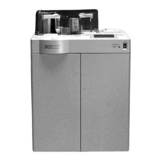
Hitachi 902 Service Manual (428 pages)
AUTOMATIC ANALYZER
Brand:
Hitachi
| Category:
Measuring Instruments
| Size: 4.58 MB
Table of Contents
Service Manual
1
Table of Contents
2
Product Specifications
3
Overall System
4
Product Specifications
4
Sampling System
5
Reagent System
6
Reaction System
7
Photometric System
8
ISE (Option)
8
Deionised Water
9
Installation Conditions
9
User Interface
9
Accuracy Control
10
Analytical Methods
10
Data Storage
10
System Interface
11
Options for Analyzer
11
Troubleshooting
12
Alarm Code Table
13
Calculation Items
30
Buzzer Output for Small-Size Automatic Analyzer
36
LCD Display Alarm
36
Output of Boot Error
36
Output to Console
36
Contents of Output
37
Kinds of Console Message Output
37
Motor Control Alarms
38
Operation Check Procedure at Occurrence of Alarm
39
At Input of START Key in STANDBY Status
41
Parameter Check
41
Processing Flow
41
Details of Parameter Check
42
Details of Twin Test Simultaneous Analysis
46
Data Alarm
47
Data Alarm Registration Flow
47
Data Alarm Code List
48
Data Alarm Codes
49
Calibration Alarm
61
ISE Data Alarms
61
Registration of Data Alarm "Sample Short"
63
Alarm Check Method
64
Duplication Check
64
Photometry Assay Calibration Check
64
SD Check of Approximate Expression
64
Automatic Correction of Reaction Limit Level
65
Reaction Limit Level Check
65
Relationship between Alarm Name and Photometric Point
65
Calibration Check
66
Electrolyte Compensable Range Check
66
Handling of Calibration Result with Comment
66
STD Check
66
Reaction Linearity Check
67
Antigen Readdition Method
68
Prozone Check
68
Reaction Rate Ratio Method
68
ISE Calibration Alarm Check
70
ISE Data Alarm Check
71
Calibration
72
Check and Set Alarm of each Data
72
Routine Sample Measurement
72
Calculation Error Factors
73
Details of Data and Alarm Outputs Resulting from Calibration
73
Sample Error Factors
73
List of Calibration Output Media
75
Relationship between Alarm and Output in Calibration
75
Retry Code Table
76
Logging Program List
77
Page Length
78
Paper Feed
78
Printing Performance
78
Printout with no Blank Space
78
Alarm Data
79
Daily Alarm Trace
79
Details of Printout
79
Retry Data
79
Instrument Status Code Table
80
Cumulative Alarm Trace
81
Printout System
81
Alarm Trace Printout (CUMULATIVE)
83
Alarm Trace Printout (DAILY)
83
Parameter Code List
84
Contents of Printout
85
Parameter Printout
85
Program Check Printout
85
Communication Trace
86
Printing Items and Their Contents
86
Presence/Absence of Error Message and Printout System
87
Control Codes and Corresponding Character Strings Printed
88
Communication Trace Printout
89
Cumulative Instrument Operation List
90
FD File Management
91
Flow Path Diagrams
92
List of Solenoid Valves
93
Overall Piping Diagram
94
Flow Rate at each Location
95
Wash
96
Details of WASH Processing
96
Carry-Over Evasion Function
98
Method of Carry-Over Evasion
98
Condition for Carry-Over Evasion
98
Carry-Over Evasion-Specified Pattern
98
Examples of Evading Procedure
99
Measure for ISE
99
Specification from Screen
99
Probe Washing Cycle
99
Priority of Carry-Over Washing
102
Block Diagrams
103
Model 902 Operating Principle
104
System Configuration of 902
104
Principle of 902
105
Measuring Principle
105
Operation of Mechanisms
105
Reaction Cuvette Rinsing and Water Blank Measurement
105
2Nd and 3Rd Reagent Addition and Stirring
106
Rinsing
106
Analytical Flow
107
Flow of Analysis
107
Operating Position
108
Operating Position of each Mechanism Around the Reaction Disk
108
Block Wiring Diagram
109
Ise
110
Functional Specifications of Model 902 ISE
111
ISE Principle
112
Outline of ISE Unit
112
Movement of Reaction Disk (Model 902)
113
Error Handling
114
Mechanical Operation When Reagent Is Short
114
Mechanical Operation When Sample Is Short
114
Configuration of ISE Hardware
115
ISE Hardware Configuration
115
Internal Standard Solution Pipetting + Water + Stirring
116
ISE Measurement Sequence
116
Sample Aspiration
116
Sample Pipetting
116
Internal Standard Solution Aspiration
117
ISE A/D Conversion
118
ISE A/D Conversion Timing
118
ADC Setting Parameters
118
ISE ADC Calibration Timing
118
Time Chart
119
Routine Plus ISE Time Chart
120
ISE Wash Time Chart
131
Switch Setting
134
Short Pins on Mother Board
135
Setting of DIP Switch on ECPU237 Board
135
Setting of DIP Switches on EMOT200 Board
135
Sw2
136
Log Amp (P/N 707-5009)
136
Ise Amp (P/N 707-5023)
136
Setting of YD-702D-6539 Short Plugs
137
Setting of YD-702D-6037D Short Plugs
138
Function of each Short Plug
139
Explanation of Functions
141
Explanation of Function
142
Routine Analysis Plus Wash
143
Timing Charts
143
Reset
144
Reset Time Chart
144
T/M Cell Blank Measurement
145
Air Purge
146
Probe Adjustment
147
Operation
148
Sample Probe Status Transition
148
Reagent Probe Status Transition
149
Operation (Photometry/Ise Measuremment Sequence)
150
Photometer Check
152
Incubator Water Exchange
153
Water Exchange
153
Measurement
154
ADC Timing
155
Configuration of Photometry ADC Hardware
156
Configuration of Temperature ADC Hardware
157
Temperature Measurement Data Flow
158
Incubator Temperature (Pt Feeler)
159
MPX Data
159
Temperature Calculation Formula
159
Temperature Measurement Sequence
159
Alarm Specifications
160
Outline of Function
161
Status Transition (Routine/Easy Analysis)
162
Calculation of Measurement End Time (Bath Processing)
166
Control Sample/Calibration Sample
166
Routine Sample
166
Scheduling When Sample Is Insufficient
166
Calculation Equation
167
Difference from Actual Analysis Time
167
Initialize Status
168
Instrument Status
168
POWER up Processing
168
Reset Status
169
Standby Status
170
Operation (Reaction Disk)
171
Explanation of Photometric Point
172
Operation (Photometry Assay)
172
Definition of Control Variable
173
Operatiton (Sample Disk)
173
Rotation Control System
173
Discharge of Cell Blank Water
174
Operation (Cell Rinse Mechanism)
174
Rinse Tip Wash
174
Status Transition for Cell Rinse
174
Details of Reset
176
Maintenance Functions
176
R. Probe Mechanism
177
Rinse Mechanism
177
Sampling Mechanism
177
Stirring Mechanism
177
Mechanism Check
178
Details of Mechanism Check
179
Incubator Water Exchange
183
Details of Incubator Water Exchange
184
Cell Blank
185
Photometer Check
186
Precision Check
187
Screen Configuration
188
Screen Transition
188
Screen Transition Diagram
189
Motors, Detectors and Fuses
194
Motor List
195
Detector List
196
Fuse List
197
Fuses on ACDIST Board (Rear Right Side)
197
Fuses on DRV Board (Front Right Side)
197
AC Fuses (on ACDIST Board)
198
Fuse Arrangement ( AC/CD)
198
DC Fuses (on DRV Board)
199
Motor and Detector Position
200
Sensor Logic
201
Analytical Methods
203
Analytical Method Table
204
Examples of Reaction Time Course
206
Types of Calibration
207
Description of Model 902 Polygonal Line Calibration
210
Formula of Calibration Curve
210
Alarm Check
211
Concentration Calculation in Polygonal-Line Calibration
211
Photometry Assay Concentration Calculation
212
Calculation of K Factor
212
Calculation of S1ABS
212
Calculation of Sample Concentration
213
Dual-Wavelength Compensation
214
Supplementary Explanation
214
Cell Blank Compensation
215
Electrolyte Concentration Calculation
216
Calculation of SL (Slope Value)
216
Concentration Calculation of Internal Standard Solution
216
Calculation of Compensation Value (C.VALUE)
216
Circuit Diagrams
218
Circuit Diagrams
219
Overall Wiring Diagram
220
ECPU237 Board (271-3724)
221
Parts Mounting Diagram
221
Explanation of Front Panel
222
Miscellaneous
222
Explanation of SW1 Bits
223
External View of DIP Switch
223
Setting of DIP Switch
223
Ethernet (AUI) Connector Signal Table
225
RS-232C (1 Channel) Connector Signal Table
225
RS-232C (4 Channels) Connector Signal Table
225
Connector Table
226
VME Bus Connector Signal Table (J1)
226
VME Bus Connector Signal Table (J2)
227
EMIO100 Board (271-3786)
228
Explanation of Circuit Board
228
External View
228
Differences from Conventional AD System
229
LED and VR
229
Counting of Discharge Time with Counter
230
Operational Waveform
230
EMOT200 Board
232
Number of Controls by EMOT200 Board
232
Explanation of LED
233
Block Diagram of EMOT200 Board
234
Arrangement of Circuit Boards
235
MVSB100 Board (271-3789)
235
Vrt - 250 Mvsb100
237
DI Board (713-5000)
242
Generation of ADC Timing Signal
243
DI Circuit 27135200
244
DRV Board (713-5001)
249
ACDIST Board (BM, BMC)
261
RSDIST Board (713-5003)
263
LOG AMP Board (707-5009)
268
Confirmation of ISE AMP Voltage
270
ISE AMP Board
270
ISE AMP Board Signal Address
270
E. SENSOR Board
272
SENSOR Board (707-5041)
272
LED Board
274
LED Circuit Diagram
274
Cross Wiring Referenc
275
Cross Wiring Reference
276
Installation
304
Analyzer Unit Unpack Manual
305
902 Layout and Installation Conditions
307
Items to be Prepared by Customer
308
Specifications of Deionized Water Supply Unit for Model 902
309
Analyzer Packed in Shipping Crate
310
Check for Quantity
310
Unpacking
310
Setting of Instrument
311
Wiring and Piping
311
Adjustment of Water Level in Incubator
312
Fixing of Instrument
312
Operation after Turning on Power
312
Preparation for Analysis
312
Adjustment and Check of each Part
313
Adjustment of Reagent Probe and Stirring Rod
313
Adjustment of Sample Probe Position
313
Check of Rinse Mechanism
314
Check of Rinse Water Volume
314
Position of Nozzle of Rinse Mechanism
314
Position of Reagent Probe and Stirring Rod
314
Operation for Completion and Others
315
Configuration
316
Explanation of File (Name and Contents of File)
316
Install Program
316
Display of Installation Menu Screen
317
Installation Instruction Screen
317
Procedure for Installation of Product Program
317
Waiting for Selection of Installation Function
317
Screen Information Transfer Screen
318
System Menu Screen
318
Waiting for Request to Initialize Flash Memory
318
Display of Flash Memory Initialization
319
Display of Installation Start
319
Installation Display Screen
319
Check Items
320
Procedure for Installation of Screen Information (Initialization)
321
Procedure for Initial Setting of LCD Module
322
Screen Displayed in Case of Failure in Screen Information Transfer
322
Initial Screen
322
How to Display System Menu
323
Maintenance Mode Menu Screen
323
Memory Initialization
324
Memory Switch Setting 1
324
DIP SW Setting Status Display
325
Maintenance and Inspection
326
Adjustment Specifications
328
DC Power Supply Adjustment and Checks
329
Electrical Adjustments
329
LOG AMP Board Adjustment
330
SW1/SW2 Settings and Corresponding Trimmers
330
ADC Timing Adjustment
331
ADC Timing Waveform Specification
331
Reaction Bath Temperature Adjustment
331
Barcode Reader Switch Setting
332
Settings of each SW at Shipment
332
Barcode Reader Positioning
333
Barcode Settings
333
How to Remove Main Unit Top Cover
336
LCD Touch Panel
336
Replacement of Backlight on LCD Touch Panel
336
Sample Arm Unit
336
Reagent Arm Unit
337
Sample Disk
337
Stirring Mechanism
337
Reaction Bath
338
Reagent Disk (Cooling Unit)
338
DC Power Unit
339
Fdd
339
Rinse Mechanism
339
Probe Adjustment
340
Functions
341
Details of Probe Adjusting Process
342
Details of Operation
342
Extent of Operation
342
Explanation of Symbols in Operation Diagram
342
Adjustment of Cup Height for S.probe Descent
343
Probe Descent Position
343
Stroke Identification for Sample Container
344
Setting of Sample Containers at S.probe Adjustment
344
R.probe Rotation Adjustment
345
Stirring Rod Rotation Adjustment
345
Adjustment of R.probe Descent to Bottle Position
346
Oem
347
DC Power Supply
348
Oem
348
24 V DC Power Supply
349
12 V Power Supply
350
Function
351
Reagent Refrigerator
351
Specifications of Cooling Unit
351
Specifications of Electrical Components
351
Refrigerator Wiring Diagram
352
Fdd (Yd-702D-6539D-021051)
354
Specifications
354
Connector Pin Arrangement for DC Power Supply
355
Connector Pin Arrangement for Interface
355
Electrical Specifications (FD Interface Signal)
356
F/D Interface Driver/Receiver
356
Configuration
357
Printer (FTP-020UCS530-#01A)
357
Specifications
358
Interface
359
Connectors
360
Power Connector
360
Barcode Reader (CCD System)
361
Name of each Part
361
Specifications
361
LCD Touch Panel
362
Specifications of Display Section
362
Specifications of Communication
363
Pin Arrangement
364
Connecting Procedure
365
Connector Pin Arrangement of NT20S
365
System Interface
366
Overview
368
Frames
369
Outline of Text
369
BCC (Block Check Character)
370
CKSH (Checksum High) and CKSL (Checksum Low)
370
Communication Function List for Measurement Result Data
371
Communication Function List for Test Selecting Information
371
Communication Functions
371
Frame List
374
Frames
374
Data Transmission Control Procedure
376
Establishment of Data Link
376
Response to Information
376
Response to Information Message
377
Response from Host
378
Transfer of Communication Control Message
378
Transfer of Test Selecting Information
378
Difference in Transfer between SUS and REC Frames
379
In Sending SUS Frame from Analyzer
379
Transfer of Analytical Data
380
Transmission Procedure in Normal Case
380
Transmission Procedure in Special Case
380
Resending Request
381
Basic Control Procedure
382
Termination and Restart of Communication
383
Details of each Frame and Priority
384
Priority
384
RESULT ONLY Mode
384
Reception Time-Out
385
Retry Due to Time-Out
385
Retry of Communication
385
Transmission Time-Out
385
Status Transition
386
Status Transition Matrix (in Transfer of Analytical Data Alone)
388
Status Transition Diagram
390
Text Configuration Corresponding to Contents of each Frame
391
Text Configuration Table
391
Composition of each Text
392
RES: Text of Analytical Data Request for Specific Sample
392
Text for Non-Specific Request
392
Contents of Text
393
SPE: Specification of Test Selection (from Host to Analyzer)
393
Analytical Data Transfer (from Analyzer to Host)
397
Text Size and Composition
397
Transfer of Photometry-Assay Calibration Data (from Analyzer to Host)
402
Data Composition
403
SD Value Information (8 Characters)
403
Transfer of ISE Calibration Data (from Analyzer to Host)
403
Data Alarm for each Channel (1 Character)
404
ISE (Electrolyte) Type (1 Character)
404
ISE Calibration Data (72 Characters)
404
Contents of Text
405
Details of Function Character (Fu)
405
Composition of Sample Information
406
Details of Sample Information
406
Sample Information
406
Details of Request for each Channel
407
Test Selecting Information
407
Comment Information (from Host to Analyzer)
408
Error Check Function
409
Overview
410
Specifications of Communication Trace
410
Trace Data Storage Timing
410
Transfer of Analytical Data Alone
410
Hardware Specifications
411
Other
411
Overview
411
Resetting of Trace Data
411
Trace Data Storage Capacity
411
Current Loop
412
RSDIST PC Board
412
Signal Assignment
413
RS-232C Interface Signal Level and Meaning
414
Interface Signal
414
Meaning of Interface Signal
414
RS-232C Communication
415
Connector Position
415
Connecting Cable and Cable Length
415
20 Ma Current Loop Interface Signal Level and Meaning
415
Example of Connection
416
Measure for FG
416
Example Connection for RS-232C Communication
416
Requirements for FG Cable
416
Signal Input Circuit
417
Communication Monitor
417
Cautions on Connection with External System
420
Operation Flow Diagram
421
Supplementation
422
Glossary
422
Communication Timing Chart
424
Composition of Message
424
Characteristics
424
Processing Flow Diagram of System Interface
426
ASCII Code Tables
427
7-Bit Roman Character Code Set
427
Advertisement
Advertisement
Related Products
Hitachi SelecSet 900 Series
Hitachi CJ 90VAST
Hitachi NR 90 AC5
Hitachi 9960
Hitachi 9900 Series
Hitachi 9 Amp
Hitachi 915/4160
Hitachi 951/7453
Hitachi 951/7460
Hitachi DS 9DVFDS 12DVF
Hitachi Categories
Projector
Air Conditioner
Drill
Power Tool
TV
More Hitachi Manuals
Login
Sign In
OR
Sign in with Facebook
Sign in with Google
Upload manual
Upload from disk
Upload from URL