Sign In
Upload
Manuals
Brands
GE Manuals
Iron
MS6001B
GE MS6001B Manuals
Manuals and User Guides for GE MS6001B. We have
2
GE MS6001B manuals available for free PDF download: Maintenance Instructions Manual, Manual
GE MS6001B Maintenance Instructions Manual (371 pages)
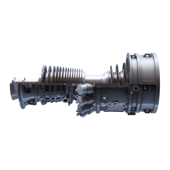
Gas Turbines With DLN-1 Combustion Systems Gas Only
Brand:
GE
| Category:
Inverter
| Size: 2.31 MB
Table of Contents
Table of Contents
5
List Illustrations
7
Table of Contents
7
Figure Title
8
Notes, Cautions and Warnings
11
Introduction
15
Operating Factors Affecting Maintenance
15
Maintenance Practices
16
Types of Inspections
17
Combustion Inspection
18
Hot Gas Path Inspection
18
Inspection Intervals
19
Major Inspection
19
Special Inspections
19
Parts
20
VIGV Bushing Inspection Schedule
20
Parts Life-Factors
21
Effect of Fuel
21
Effect of Starts
22
Maintenance Inspections - Model Series 6000 Estimated Outage Requirements
22
Types of Shutdown Inspections
23
VIGV Bushing Wear Inspection Procedure
24
Standard Practices
27
Torque Values for Bolts and Studs
31
Typical Flange Joint Makeup
31
Bolt and Stud Elongation Values
32
Recommended Solvents, Sealanats and Cleaners
33
Anti-Seize Compound, High Temperature
35
Anti-Seize Chemical Constituent Guidelines
35
Lubricant Guidance
36
Tools and Equipment
37
Standard Tools
37
Special Tools
41
Guide Pin Compressor Casing
44
Guide Pin Inlet Casing
44
Guide Pin Bearings and Exhaust Frame
45
Guide Pin Compressor Discharge and Turbine Casing
45
Jacking Rod, Number Two Bearing Disassembly
46
Typical Jacking Bolt, Unit Casings
46
Fixture Arrangement, Number Two Bearing and Coupling
47
Fuel Nozzle Wrenches
48
Tool, Alignment Pin
48
Tool, Transition Piece Side Clearance
49
Tool, Transition Piece, First Stage Nozzle
49
Alignment Fixture
50
Staking Tool, Fuel Nozzle
50
Combustion Liner Puller
51
Lifting Beam
52
Rail Fabrication, Hoist
52
Cable Sling
53
Trolley Hoist
53
Clevis Hook, Foundry
54
Typical Anchor Shackle
54
Connection Link
55
Ratchet Gear Come-Along
55
Chain Sling
56
Clevis Hook, Grab
56
Pulley Nozzle Segments
58
Typical Borescope Kit
59
Rail Channel, Trolley
60
Lifting Beam, Inlet Silencer
61
Lifting Beam, Inlet Transition
62
Inlet Elbow
63
Typical Accumulator Charging Equipment
64
Flushing Block, Servo Valves
65
Hose Clamp Pliers
65
Insertion and Extraction Tool
65
Tubing, Insert and Male Connector
66
Maintenance Parts Recommendations
67
Ordering Renewal Parts, Repair and Replacement Parts
67
Returning Turbine Parts for Repair/Replacement
67
Combustion Inspection Recommended Spare Parts
68
Major Inspection Recommended Spare Parts
76
Auxiliary and Controls Systems Maintenance
89
Periodic Inspection Schedule
92
Inspection and Maintenance Procedures
105
Flowmeter
107
Pressure Switches and Gauges
107
Standard Maintenance Items
107
Thermometers
107
Control Devices
108
Panel Meters
108
Temperature Switches
108
Vibration Detectors
108
Temperature Control Valves
109
Hydraulic/Mechanical Equipment
110
Relief Valves
110
Servovalves
110
Solenoid Valves
110
Check Valves, Orifices and Orifice Check Valves
111
Hydraulic Supply Filters
111
Lube Oil Filters
111
Accessory and Turbine Compartment Vent Fans
112
DC Motors
112
Heating, Cooling and Ventilation
112
Motors
112
AC Motors
113
Couplings
113
Lube Systems Maintenance
113
Unit Piping Systems
113
Lube Oil Immersion Heaters
114
Mist Eliminator
114
Mist Eliminator Fan
114
Radiator and Header Assemblies
114
Cooling System Checks
115
Cooling Water System
115
Flow Checks
115
Pipe Couplings
115
Cooling Water Fans
116
Flow Versus Pressure Drop
116
Water Tank
116
Cooling Water Pump
117
False Start Drain Valve
117
Fuel Gas Stop Ratio and Control Valve
117
Fuel Gas System
117
Auxiliary Hydraulic Supply Pump
118
High Pressure Control Oil System - Hydraulic Supply
118
Hydraulic Supply Manifold
118
Main Hydraulic Supply Pump
118
Compressor Bleed Valve
119
Cooling and Sealing Air System
119
Piping System
119
Starting System
119
Accessory Gear Train
120
Fire Protection System
120
Starting Clutch
120
Torque Converter
120
Fire Detectors
121
High Pressure Storage Cylinders
121
High Pressure System
121
System Package Lagging
121
High Pressure System Tests
122
Low-Pressure CO System Electric Release and “Puff” Tests
122
Electric Release Test
123
“Puff” Test
123
Exhaust Thermocouples
124
Temperature Control
124
Wheelspace Thermocouple Temperature Limits
124
Flame Detection and Protection System
125
Control Panel and Power Supply Components
126
Magnetic Pickups
126
Overspeed Protection System (Electronic)
126
Speedtronic Controls and Equipment
126
Contact Arcing
127
Contact Cleaning
127
Contact Replacement and Pressure
127
Relay Contacts
127
Battery Charger
128
Battery System
128
Circuit Breakers
128
Motor Control Center
128
Generators
129
Load Gear and Collector Compartments
129
Magnetic Contactors and Starters
129
Starting Motor Limitamp Contactor
129
Bypass Door
130
Inlet Air Systems Maintenance and System Equipment (Gas Turbine)
130
Inlet Filters
130
Inlet Screen
130
Inlet Guide Vanes
131
Evaporative Coolers
131
Water Flow Adjustment
131
Shut down Pump Operation
131
Control Cab
135
Running Inspections
135
Housekeeping
135
Scheduled Turbine Maintenance
135
Turbine Compartment
136
Accessory Compartment
136
Data Recording
137
Off-Base Systems
137
Operating Data
139
Borescope Inspections
146
Nozzle Clearance Measurements
146
Eddy Current Testing
146
Borescope Inspection Programming
147
Equipment Required
147
Areas of Inspection
147
Service Support for Borescope Inspections
148
Inspection Procedure
148
MS-6001B DLN-1 Borescope Access Holes Location
151
Borescope Access Hole Locations
152
Borescope Light Supply
153
Borescope Probes and Light Supply Connector
154
Scope Support Fixture
155
TV Monitor Presentation
156
Disassembly Procedures for MS-6001B DLN-1 Combustion Systems
161
How to Prepare the Turbine Compartment Roof for Removal
161
How to Remove the Cooling Water Lines from Flame Detectors
161
How to Remove the Turbine Compartment Roof and Side Panels
161
Combustion Chamber Arrangement.
162
Combustion System Components
163
Inside End Cover/Primary Fuel Nozzle
164
Gas Fuel Nozzle Assembly
165
Transition Piece
166
How to Remove the False Start Drain Tubing
167
How to Remove the Primary Gas Fuel Lines
167
How to Remove the Transfer Fuel Gas and Secondary Fuel Gas Lines
167
Swagelok Fitting with Stop Collar
167
False Start Drain Piping
168
How to Remove the Secondary Fuel Nozzle
169
How to Remove the Spark Plugs
169
Secondary Fuel Gas Nozzle Assembly
170
Suggested Storage and Moving Rack for Secondary Fuel Nozzles
171
Spark Plug Assembly
172
How to Remove the Eleventh Stage Cooling and Sealing Air Lines
173
Remove Fuel Nozzle – End Cover Assemblies
173
Remove Crossfire Tube Retainers, Combustion Liners, Crossfire Tubes
174
End Cover with Primary Nozzles and Guide Pins
175
Typical Multi-Nozzle Assembly, Moving and Storage Fixture
175
Crossfire Tube Assembly
176
Location of Crossfire Tube Spring Retainer
176
Cap and Liner Removal Tool
177
How to Remove the Outer Combustion Casings and Flow Sleeves
178
Remove the Access Port Blank Flange from Upper Half Turbine Casing
178
Remove the Access Port Flange from Atomizing Air Extraction Manifold
178
How to Remove the Transition Pieces
179
Combustion Outer Casing
180
Air Extraction Manifold
181
Outer Casing Arrangement
182
Flow Sleeve
184
Disassembly End Seal and Stop Block
185
Transition Piece Lockplating Aft Bracket Bolts
186
How to Inspect Primary Fuel Nozzles
187
Inspection Procedures for MS-6001B DLN-1 Combustion Systems
187
End Cover/Fuel Nozzle Arrangement
188
Inspect and Clean Primary Fuel Nozzles
190
Inspect and Clean the End Covers
190
Primary Fuel Nozzle Detail
190
Fuel Nozzle Cleaning Parts Basket
191
Typical Fuel Nozzle Cleaning and Rinsing Tank
191
Recommended Cleaning Compounds
192
How to Disassemble and Inspect Secondary Fuel Nozzles
194
How to Reassemble the Primary Fuel Nozzles
194
How to Reassemble the Secondary Fuel Nozzles
195
How to Inspect Combustion Liners
196
How to Test Secondary Fuel Nozzles
196
Cap and Liner Details
197
Cap, End View
197
Combustion Liner Spring Seal Inspection Areas
198
Typical Slot Cooled Combustion Liner Rolled Ring Section
198
Inspection Limits
200
How to Inspect Crossfire Tubes and Spring Retainers
203
How to Inspect Transition Pieces
203
Transition Piece Inspection Area Locations
208
How to Inspect and Test the Spark Plugs
209
How to Inspect Combustion Casings
209
How to Inspect Combustion Flow Sleeves
209
How to Inspect the First Stage Nozzle
209
How to Inspect and Test the Flame Detectors
212
How to Install Transition Pieces
215
How to Perform Transition Piece Preassembly Inspections and Checks
215
Reassembly Procedures for MS-6001B DLN-1 Combustion Systems
215
Transition Piece Aft Bracket Guide Pin Assembly
216
Transition Piece Support Clamp Assembly
217
Transition Piece Side Seal Clearance
219
Transition Piece Centralization Checks Setup
220
Transition Piece Support Clamp Assembly Checks
221
How to Install the Outer Combustion Casings and Flow Sleeves
222
Transition Piece First-Stage Nozzle to Retaining Ring Clearance Checks
223
Transition Piece Lockplating Aft Bracket Bolts.
224
Assembly of End Seal and Stop Block Assembly to Transition Piece
225
Combustion Flow Sleeve
226
Outer Casing and Flow Sleeve Assembly
226
Install the Outer Crossfire Tubes, Packing Rings
227
Install the Sealing Rings and Split Washers
227
Outer Combustion Casing Alignment Pin
227
How to Assemble the Primary Flame Detectors and Spark Plugs
228
How to Install the Inner Crossfire Tubes and Cap and Liner Assemblies
228
Outer Crossfire Tube
229
Primary Flame Detector
232
How to Install the Primary Fuel Nozzle/End Cover Assemblies
233
How to Install the Secondary Fuel Nozzles
233
How to Install the 11Th Stage Cooling and Sealing Air Lines
234
How to Install the Primary, Secondary and Transfer Gas Fuel Lines
234
How to Reconnect the False Start Drain Lines
234
How to Assemble the Turbine Compartment Roof and Side Panels
235
How to Install the Secondary Flame Detectors
235
How to Reconnect the Ignitors
235
Install the Turbine Casing Blank Cover on Hand Hole Port
235
How to Perform Cleanup, Visual Inspections and Prestart/Startup Checks
236
Hot Gas Path Inspection Contents
241
Disassembly Procedures (Hot Gas Path Inspection) for MS-6001B DLN-1 Equipped Machines
243
How to Remove Exhaust and Inlet Plenum Access Panels
243
Perform Combustion Inspection Disassembly Operations
243
How to Take Initial Compressor and Turbine Rotor Positioning Checks
244
How to Disconnect Wiring and Conduit in Turbine Compartment Area
245
Rotor Position Probe
246
How to Place Mechanical Support Jacks under Turbine Casing
247
Support Jack Locations for Compressor and Turbine Casings
248
How to Remove Upper Half Turbine Casing
249
Remove Turbine Casing Bolts
249
Remove Upper Half First Stage Nozzle Eccentric Pin
249
Turbine Casing Rigging for Removal
250
Guide Pin Locations
251
How to Take Turbine Clearance Checks
253
Left Side and Right Side
253
Rotor Float
254
Turbine Rotor Clearances
254
Loading for Second-Stage Nozzle Clearances
256
Loading for Third-Stage Nozzle Clearances
256
How to Unbolt and Remove Transition Pieces
257
Nozzle Clearance Wedging Block
258
Set Point “A”
258
Proper Method for Reading Axial Clearances
259
Set Point “B”
259
How to Remove Upper Half First Stage Nozzle
260
How to Take First Stage Nozzle Radial Concentricity Checks
260
First-Stage Nozzle Concentricity Checks
261
How to Remove Lower Half First Stage Nozzle Eccentric Pin
262
First-Stage Nozzle Lifting Angles for Support Pad/ Pin Type Nozzle
263
How to Remove Lower Half First Stage Nozzle
264
How to Remove Lower Half Second and Third Stage Nozzle Segments
264
Remove Lower Half Second/Third Stage Nozzle Radial Retaining Pins
264
Second and Third-Stage Nozzle Segments
265
How to Remove Upper Half Second and Third Stage Nozzle Segments
267
Remove Upper Half Second/Third Stage Nozzle Radial Retaining Pins
267
How to Inspect First, Second and Third Stage Nozzles
269
Inspection Procedures (Hot Gas Path Inspection) for MS-6001B DLN-1 Equipped Machines
269
Perform Combustion Inspection Procedure Operations
269
Corrosion or Erosion of Nozzles
270
Nozzle Cracking
270
Nozzle Foreign Object Damage
270
Nozzle Sidewall Cracks
271
Nozzle Partition Fillet Cracks
272
Nozzle Sidewall Surface Cracks
272
Unacceptable Crack Propagation
273
Unacceptable Cracks
273
How to Inspect First, Second and Third Stage Turbine Buckets
274
Recommendations
274
First Stage Buckets
275
First-Stage Bucket Details
276
Second and Third-Stage Bucket Details
277
Second and Third Stage Buckets
278
First-Stage Bucket Repair Limits
279
Radial Seal Pin Grooves
280
Wheelspace Seals/Angel Wings
280
Second and Third-Stage Bucket Repair Limits
281
Radial Seal Pin Groove Repair Limits
282
Wheelspace Seal Angel Wings Cross Sections
283
First Stage Shrouds
284
How to Inspect Shroud Blocks
284
Shroud Tip Rework
284
Shroud Tip Rework Limits
285
Turbine Shroud Blocks
286
How to Inspect Second and Third Stage Nozzle Diaphragms
287
Second/Third Stage Shrouds
287
Third-Stage Nozzle and Diaphragm
289
How to Make First Stage Nozzle Ellipticity Checks
290
How to Install Lower Half First Stage Nozzle and Eccentric Pin
291
Reassembly Procedures (Hot Gas Path Inspection) for MS-6001B DLN-1 Equipped Machines
291
Eccentric Pin Retaining Strap Weld
293
First-Stage Nozzle Tangential Support Pin and Hardware Assembly
295
Install Lower Half Second/Third Stage Nozzle Segments
296
Install Wheelspace Thermocouples in Lower Half Second/Third Stage
297
Second-Stage Nozzle Seals and Radial Retaining Pins
298
Third-Stage Nozzle Seals and Radial Retaining Pins
299
How to Install Upper Half First Stage Nozzle
300
How to Install Upper Half Second/Third Stage Nozzle
300
First-Stage Nozzle Support Ring with Support Pad
301
How to Recheck Turbine Clearances
302
How to Recheck First Stage Nozzle Concentricity
302
Install Upper Half Turbine Casing
303
Install Upper Half First Stage Nozzle Eccentric Pin
303
How to Install Wheelspace Thermocouple Wiring and Conduit
304
Turbine Casing Rigged for Reinstallation
305
Typical Bolt Tightening Sequence for Unit Casings
306
Remove Mechanical Support Jacks from Underneath Turbine Casing
307
Take Final Compressor and Turbine Rotor Positioning Checks
307
Perform Combustion Inspection Reassembly Operations
307
How to Assemble Turbine Compartment Roof, Side Panels and Doors
308
Exhaust Plenum Seal Segments, Forward and Aft Sides Assembly
309
How to Clean Up, Operate and Leak Check Unit
310
Major Inspection Contents
315
Disassembly Procedures (Major Inspection)
317
Perform Alignment Checks before any Unit Disassembly Is Begun
317
How to Remove Exhaust and Inlet Duct Access Panels
320
How to Remove Inlet Duct Elbow
321
How to Remove the Upper Half of the Inlet Plenum
321
Place Mechanical Support Jacks under Unit Casings and Inlet Bellmouth
322
How to Remove Upper Half Exhaust Frame
324
How to Remove Forward Compressor Casing
325
How to Remove Upper Half Inlet Casing
327
Twelve Point Bolts in Inlet Casing
328
Inlet Guide Vane Ring Support Plate and Locking Bolt
329
How to Remove Compressor Discharge and Aft Compressor Casing
330
Perform Hot Gas Path Disassembly Operations 6 Thru 11
330
How to Remove Upper Half First Stage Nozzle Support Ring
330
First-Stage Nozzle Support Ring and Support Groove
331
How to Remove the Inner Compressor Discharge Casing
333
How to Take Rotor Thrust and Compressor Clearances
333
Compressor Discharge Supported in Upright Position
334
Aft Compressor Casing Supported in Upright Position
334
Inner Compressor Discharge Casing at Initial Assembly
335
Inner Compressor Discharge Casing with Upper Half Removed
336
Perform Hot Gas Path Disassembly Procedures
337
How to Remove Upper Half Number One and Two Bearing Housings
337
Number One Bearing Housing Thrust Bearings
338
Number Two Bearing
338
Number One Bearing Housing with Upper Half Removed
339
Number Two Bearing Strap and Upper Half Number Two Bearing Housing
340
Number Two Bearing Housing with Upper Half Removed
341
Perform Hot Gas Path Disassembly
342
Inspection Procedures (Major Inspection)
343
Inspect Combustion System Components Per Combustion Inspection
343
Inspect Hot Gas Path Components Per Hot Gas Path Inspection
343
How to Inspect Inlet Guide Vanes
344
Inspect Compressor Rotor, Stator Blading, Compressor/Turbine Casings
344
How to Inspect First Stage Nozzle Support Ring
344
How to Inspect Inner Compressor Discharge Case Seals
344
How to Inspect Sleeve Bearings and Thrust Bearings
345
Rotor Support Lever for Removal of Number Two Bearing Liner Lower Half
346
Reassembly Procedures (Major Inspection)
351
Reassemble Sleeve/Thrust Bearings
351
Reassemble Upper Half Bearing Housings and Exhaust Hood Baffle
351
Recheck Compressor Clearances and Thrust
352
How to Install Inner Compressor Discharge Casing
352
How to Install Compressor Discharge and Aft Compressor Casings
353
How to Install Upper Half First Stage Nozzle Support Ring
353
Compressor Discharge Casing Bolt Tightening Sequence
355
Perform Hot Gas Path Reassembly Operations
356
How to Install Compressor Rub Ring
356
How to Install Upper Half Compressor Inlet Casing
356
How to Install Exhaust Frame
357
How to Install Forward Compressor Casing
357
Remove Mechanical Support Jacks from Underneath Unit Casings
358
Take Final Rotor Positioning Checks
358
Perform Combustion Inspection Reassembly
359
How to Install Inlet Plenum
359
How to Install Inlet Transition Piece Duct and Elbow
360
How to Reassemble Exhaust and Inlet Plenum Access Panels
360
Recheck Turbine to Load Gear and Turbine to Accessory Gear Alignment
360
How to Install Magnetic Pickup Ring, Accessory and Load Couplings
362
How to Install Coupling Guards
362
Perform Hot Gas Path Reassembly
362
Maintenance Forms
365
Advertisement
GE MS6001B Manual (31 pages)
General Electric Gas Turbine
Brand:
GE
| Category:
Iron
| Size: 1.43 MB
Table of Contents
Table of Contents
2
GE5 Gas Turbines
4
Ge10
8
Ms5001
10
Ms5002C-D
11
Ms5002E
11
Ms6001B/Ms7001Ea/Ms9001E
13
Pgt16
14
Pgt25
15
Pgt25
16
Lm6000
17
Main Components
18
Axial Compressor
18
First Stage Nozzles
19
Buckets and Wheels
19
Gas Turbine Operability
20
LNG Exploration and Production, Floating Production Units
22
Pipeline
23
Refinery and Petrochemicals
24
Service
26
Training
27
Advertisement
Related Products
GE MS5001
GE MS5002C
GE MS5002D
GE MS5002E
GE MS7001EA
GE MS9001E
GE MSD2100VWW
GE MS-PoE
GE MAC 5500
GE MAC 600 SPY
GE Categories
Refrigerator
Ranges
Microwave Oven
Air Conditioner
Dishwasher
More GE Manuals
Login
Sign In
OR
Sign in with Facebook
Sign in with Google
Upload manual
Upload from disk
Upload from URL