Sign In
Upload
Manuals
Brands
GE Manuals
Test Equipment
DPI620G-IS
GE DPI620G-IS Manuals
Manuals and User Guides for GE DPI620G-IS. We have
1
GE DPI620G-IS manual available for free PDF download: User Manual
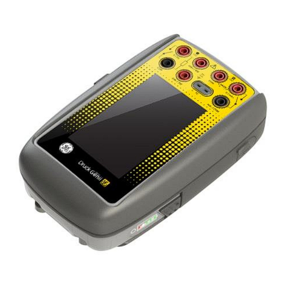
GE DPI620G-IS User Manual (248 pages)
Intrinsically Safe Calibrator and Communicator Series
Brand:
GE
| Category:
Test Equipment
| Size: 4.67 MB
Table of Contents
Table of Contents
2
Overview
10
Equipment in the Box
10
Optional Items
11
Observance of the User Manual
11
Safety
12
General Safety Precautions
12
Operation in a Hazardous Environment
13
General Warnings
15
Electrical Warnings
16
Pressure Warnings
18
Preparing the Instrument
19
Battery & Charger
20
Charging the Battery
20
Installing the Battery
22
Power On/Off
23
Power on
23
Power off
24
Power up from Standby Mode
24
Operation
25
Dashboard Navigation
25
Set Date, Time and Language
26
Themes
26
DPI620G-IS User Manual
26
Connection Diagrams
26
Alarm Status
27
Operating Modes
28
Software and Firmware Upgrades
29
Viewing Software Revision
29
Upgrading the Unit Software
29
Upgrading the HART Device Library
31
1.10 Maintenance
33
Cleaning
33
1.11 Instrument Return
34
Returned Material Procedure for USA
34
Returned Goods Procedure for Europe
35
Instrument Disposal in the European Union
36
1.12 Packaging for Storage or Transportation
37
Environment
37
1.13 Marks and Symbols
37
Electrical Operations
38
Measure & Source Functions
38
Basic Calibrator Operation
39
Saving Tasks
39
Electrical Tasks
40
Favourites
42
Custom Task
43
Function Utility Options
46
Max/Min
46
Switch Test
47
Relief Valve
48
Measurement Display Options
50
Measure and Source Operations
52
Example Procedure: Measure or Source Current
54
Example Procedure: Measure or Source Current, CH1
54
Example Procedure: Measure or Source Current, CH2
55
Example Procedure: Measure or Source Current with Internal 15V Loop Power, CH2
56
Example Procedure: Measure Current, Internal Loop Power, CH2
57
Example Procedure: Source Current with Internal Loop Power, CH2
58
Example Procedure: Measure DC Voltage
59
Example Procedure: Measure DC Voltage, CH1
59
Example Procedure: Measure DC Voltage, CH2
60
Example Procedure: Source DC Voltage, CH1
61
Example Procedures: Measure or Source Frequency Signals
62
Example Procedure: Measure Frequency Signals
62
Example Procedure: Source Frequency Signals
63
2.11 Example Procedure: Measure/Simulate RTD
64
Example Procedure: Measure/Simulate a RTD, 4-Wire Method
64
Example Procedure: Measure a RTD, 3-Wire Method
66
Example Procedure: Measure a RTD, 2-Wire Method
67
Example Procedure: Measure or Simulate a Thermocouple (TC)
68
2.13 Example Procedure: Switch Test
70
2.14 Error Indications
73
Pressure Indicator Operation (MC620-IS)
74
Parts and Assembly
75
Assembly Instructions
77
Pressure Connections
78
Procedure (Attaching External Equipment)
78
Procedure Overview
80
Set up a Leak Test
83
Set the Pressure Module to Zero
85
Error Indications
86
Data Logging Operation
87
Set-Up
89
Operation
91
File Review
91
Chart View
92
File Management
93
Erase
93
Memory Status
93
Download Files
94
Data Format
95
Documentation
96
Analysis
96
Set-Up
98
Define the Reference Channel
99
Define each Input Channel
100
Analysis Function
102
Run Procedure
103
Sequence to Upload and Download File
104
HART® Operations
105
HART® Menu Operations
105
Start-Up
106
HART® Connections
107
Power Supply from the Calibrator
107
External Loop Power
108
Communicator Attached to a Network
109
Use of Test Connections
110
Viewing Primary Variables
111
Device Polling
112
Viewing HART® Configuration
114
Start HART® SDC Application
115
6.10 HART® Toolbar
117
6.11 Data Display
118
6.12 Editing Values
119
6.13 Executing Methods
121
Method Example - Self-Test
122
Method Example - Analog Trim
123
6.14 Preferences
125
6.15 Failed to Find Device
126
HART® Offline
127
Introduction
127
Start-Up
127
Start HART® Offline
128
Create an Offline Configuration
130
Browse an Offline Configuration
131
Edit an Offline Configuration
132
Saving the Configuration
133
Uploading the Configuration
134
Working with Saved Configurations
134
7.10 Delete HART Configuration
134
Foundation™ Fieldbus
135
Introduction
135
FOUNDATION Fieldbus Configurations
135
Start up
136
FOUNDATION™ Fieldbus Connections
138
FOUNDATION™ Fieldbus Application - Connecting to a Network
142
FOUNDATION™ Fieldbus Toolbar
143
Scanning for Devices
145
Context Sensitive Menu
148
Device State
150
Troubleshooting Connection Problems
154
FOUNDATION™ Fieldbus Application - Communication
155
Device Focus View
155
Block Navigation Tree
158
Block Header Bar
160
Folder Variables
162
Displaying Parameter Help
164
Refreshing Data
165
Editing Variables
166
Methods
168
FOUNDATION™ Fieldbus Application - My Block
169
FOUNDATION Fieldbus Application - Exporting Variables
171
Viewing Exported Variables in Channel Window
172
Application Settings
173
Device Library
173
Options
173
Advanced
174
Function Finder
175
PROFIBUS PA Fieldbus
177
Introduction
177
PROFIBUS Configurations
177
Start-Up
178
PROFIBUS Connections
180
PROFIBUS Application - Connecting to a Network
184
PROFIBUS Toolbar
185
Scanning for Devices
187
Context Sensitive Menu
190
Troubleshooting Connection Problems
192
PROFIBUS Application - Communication
193
Device Focus View
193
Block Navigation Tree
196
Block Header Bar
198
Folder Variables
200
Displaying Parameter Help
202
Refreshing Data
203
Editing Variables
204
PROFIBUS Application - My Block
206
PROFIBUS Application - Exporting Variables
208
Viewing Exported Variables in Channel Window
209
Application Settings
209
Device Library
210
Options
210
Advanced
211
Function Finder
212
Calibration Procedures
214
10.1 before Starting
214
10.2 Selection Sequence
217
Calibration Procedures (CH1/CH2): Current (Measure)
218
Calibration Procedures (CH1/CH2): Current (Source)
220
Calibration Procedures (CH1/CH2): DC MV/Volts (Measure)
221
Calibration Procedures (CH1): DC MV/Volts (Source)
223
Calibration Procedures (CH1): Frequency (Measure/Source)
225
Calibration Procedure (CH1): Frequency, Pulse Amplitude (Source)
229
Calibration Procedure (CH1): Resistance (Measure) (Standard)
231
Calibration Procedure (CH1): Resistance (Measure) (True Ohms)
233
Calibration Procedures (CH1): Resistance (Source)
234
Calibration Procedures (CH1): TC MV (Measure)
236
Calibration Procedures (CH1): TC MV (Source)
238
Calibration Procedures (CH1): CJ and CJ (TC Method) (Measure)
239
Calibration Procedures: Pressure Indicator Modules (PM 620-IS)
242
General Specification
244
11.1 Introduction
244
Manufacturer
247
Display Icons
248
Advertisement
Advertisement
Related Products
GE Druck DPI 620
GE Druck DPI 610
GE Druck DPI 615
GE Druck DPI611
GE Druck DPI612
GE Druck DPI 620-IS
GE Druck DPI612- PFX
GE Druck DPI612- HFP
GE Druck DPI612- PFP
GE Druck DPI 832
GE Categories
Refrigerator
Ranges
Microwave Oven
Air Conditioner
Dishwasher
More GE Manuals
Login
Sign In
OR
Sign in with Facebook
Sign in with Google
Upload manual
Upload from disk
Upload from URL