Sign In
Upload
Manuals
Brands
Gamatronic Manuals
UPS
POWER+ PREMIUM
Gamatronic POWER+ PREMIUM Manuals
Manuals and User Guides for Gamatronic POWER+ PREMIUM. We have
1
Gamatronic POWER+ PREMIUM manual available for free PDF download: Installation Manual
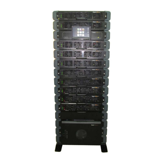
Gamatronic POWER+ PREMIUM Installation Manual (63 pages)
Brand:
Gamatronic
| Category:
UPS
| Size: 3 MB
Table of Contents
Table of Contents
3
Safety Precautions
6
1 Ntroduction
9
Figure 1: POWER + System - Major Components
9
2 Installation
10
Installation Checklist
10
Table 1: Installation Checklist
10
Connection Diagram
12
Figure 2: Connection Diagram (for Completion by the Customer)
12
Installation Procedure
13
Visual Inspection
13
Site Preparation - Physical
13
Figure 3: Ensure Sufficient Free Space at Front and Rear of the UPS
13
Site Preparation - Electrical
14
Circuit Breaker Selectivity
14
Cabling
15
Neutral Line
15
Connecting the UPS
16
Figure 4: Ac Terminals on 50 and 100 Kva Models
16
Connection Diagram for Standard 3-3 Configuration
17
Figure 5: Connection Diagram for Standard 3-3 Configuration
17
Figure 6: Connection Diagram for 3-3 Config. W/ Input Isol. Transformer
18
Figure 7: Maximum Input Current
19
Figure 8: Ac Switch and Circuit Breaker Recommendations
19
Battery
20
Battery Overview
20
Internal Batteries
20
External Batteries
20
Figure 9: Connections for Two External Battery Cabinets on 50 Kva Model
21
Figure 10: Connections for Two External Battery Cabinets on 100 Kva Model
21
Table 2: Battery Lifetime Vs Environmental Temperature
22
Special Terminal Connections
23
Figure 11: Special Purpose Terminals in STSW Tray
23
Figure 12: Close-Up of Special Purpose Terminals
23
Battery Trip Coil
24
Emergency Power-Off
24
Load on Bypass Alarm
24
Figure 13: Closer View of Dry Contact Terminals
25
Figure 14: Close-Up of Dry Contact Terminals
25
Input and Output Dry Contacts
25
Figure 15: Close-Up of Connectors on Left Rear of Controller
26
Figure 16: Pin Numbers in D9 Connectors
26
Table 3: Pin Assignments for D9 Connectors on Rear of Controller
26
Initial Startup of the System
27
Initial Configuration
28
Figure 17: Initial Configuration Wizard, "Start" Screen
28
Figure 18: Initial Config. Wizard: Password Entry
28
Figure 19: Initial Config. Wizard: Set Number of Modules
29
Figure 20: Initial Config. Wizard: Number of Battery Cabinets or Battery Compartments
30
Figure 21: Initial Config. Wizard: Set Battery Capacity
30
Figure 22: Initial Config. Wizard: Set Time Zone
31
Figure 23: Finish Configuration Wizard
31
Continuing First-Time Start-Up Process
32
Figure 24: the "Alarms" Icon Indicates Alarm Conditions
32
Define the IP Address of Power+ Premium
33
Figure 25: IP Address Configuration
33
Testing
35
Blackout Test
35
Test under Load
35
Check IP Communication with Controller
35
3 Using the Ups with a Generator
36
The Automatic Transfer Switch (ATS)
36
Figure 26: Timing Variables When Using a Generator and an ATS
36
Figure 27: Example of an ATS Control Panel
37
Cabling
38
Neutral Line
38
Figure 28: Wrong Way to Connect Power+ with a Four-Pole Switch
38
Figure 29: Acceptable Connection for Grounded Generator and 4-Pole Switch
39
Figure 30: Preferred Generator (Neutralized) and Connection (3-Pole)
39
4 Inserting and Removing Power Modules
40
Physical Insertion of a UPS Module
40
Figure 31: Push the Module in Gently but Firmly
40
Physical Removal of a UPS Module
41
First-Time Insertion of Power Modules at System Installation
41
Replacement of a Module in an Installed System
41
Figure 32: Front Panel of the UPS Module
41
Figure 33: Turning off a Module
42
Figure 34: "Status > Modules" Screen
42
Figure 35: Verifying Status of Replacement Module
43
Figure 36: Status > Modules > Output
44
Addition of a Module in an Installed System
45
Figure 37: Turning off a Module
45
Figure 38: Turning on a Module
46
Figure 39: Verifying Status of Added Module
46
Figure 40: Status > Modules > Output
47
Removing a Module from an Installed System
48
Figure 41: Turning off a Module
48
Figure 42: "Status > Modules" Screen
48
5 Installing the Lcd Screen
50
Figure 43: Remove the Mounting Block
50
Figure 44: Slightly Loosen the Nut on the Mounting Block
50
Figure 45: Attach the Mounting Block to the Rear of the LCD Panel
50
Figure 46: Attach the Screen to the Receiver on the Top Front of the UPS
51
Figure 47: Connect the Cable to the Right Rear of the LCD Screen
51
6 Circuit Breaker Selectivity
52
Figure 48: a Ups's Bypass Circuit
52
7 Using a Maintenance Bypass Switch
54
Putting the UPS into Maintenance Bypass Mode
54
Returning the UPS to Normal Operation
54
8 Remote Monitoring Panel ( Option )
55
Figure 49: the Remote Monitoring Panel
55
Table 4: Leds on the Remote Monitoring Panel
55
Figure 50: Connecting the Remote Monitoring Panel
56
9 Related Products 9.1 G4
57
Figure 51: Gmaci G4
57
G-Eye
58
Figure 52: G-Eye
58
10 Preventive Maintenance
59
11 Service and Repairs
60
12 Power + Premium Specifications
61
Table 5: System Technical Specifications
61
Advertisement
Advertisement
Related Products
Gamatronic Power+
Gamatronic power+ sa
Gamatronic POWER PLUS
Gamatronic POWER Plus Premium SA 15
Gamatronic B60US-IB
Gamatronic Centric 100 kVA
Gamatronic CENTRIC 100 kW
Gamatronic Centric 120 kW
Gamatronic Centric 125 kVA
Gamatronic Centric 150 kVA
Gamatronic Categories
UPS
Measuring Instruments
Server
More Gamatronic Manuals
Login
Sign In
OR
Sign in with Facebook
Sign in with Google
Upload manual
Upload from disk
Upload from URL