Sign In
Upload
Manuals
Brands
Gamatronic Manuals
UPS
power+ sa
Gamatronic power+ sa Manuals
Manuals and User Guides for Gamatronic power+ sa. We have
3
Gamatronic power+ sa manuals available for free PDF download: User Manual
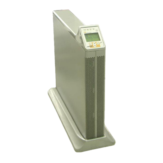
Gamatronic power+ sa User Manual (174 pages)
20 KVA, 30 KVA, AND 40 KVA MODELS
Brand:
Gamatronic
| Category:
UPS
| Size: 5.49 MB
Table of Contents
Table of Contents
3
Safety Precautions
13
Do's
13
Don'ts
14
1 Introduction
17
POWER + SA Has Many Unique Features
17
Figure 1: 20, 30, or 40 Kva Configuration in a Compact Cabinet
18
System Controller
19
Inverter Boards and Rectifier Boards
19
Static Switch (ST/SW)
19
Battery
19
2 Operating Modes
20
Normal Operation
20
Battery Operation
20
Bypass Operation
21
3 User Interface
22
Control Panel
22
Figure 2: Control Panel
22
POWER + SA Control Screen
23
Load-Level Bar Graph
23
Figure 3: POWER+ Control Screen
23
Navigation and Operation Keypad
24
Figure 4: Navigation and Operation Keypad
24
Status Indicators
25
Figure 5: Status Indicators
25
Table 1: Status Indicators
25
Operation Buttons
26
Network Access Indicator
26
Figure 6: Network Access Indicator
26
Table 2: Operation Buttons
26
Table 3: Network Access Indication
26
POWER + SA Operation Modes
27
Normal Operation
27
Battery Operation
27
Figure 7: POWER+ Control Screen in Normal Operation
27
Figure 8: Normal Operation Indication
27
Figure 9: Ac Power Failure
27
Bypass Operation (Automatic)
28
Bypass Operation (Manual)
28
Emergency Power-Off - EPO (Manual)
28
Figure 10: Ac Power Failure Indication
28
Figure 11: UPS in Bypass Mode
28
Figure 12: UPS in Bypass Mode
28
4 Installation
29
Installation Checklist
29
Table 4: Installation Checklist
29
Connection Diagram
31
Figure 13: Connection Diagram (for Completion by the Customer)
31
Installation Procedure
32
Visual Inspection
32
Site Preparation - Physical
32
Site Preparation - Electrical
32
Cabling
33
Neutral Line
33
Figure 14: Wrong Way to Connect POWER + SA with a Four-Pole Switch
34
Figure 15: Acceptable Connection for Grounded Generator and 4-Pole Switch
35
Figure 16: Preferred Generator (Neutralized) and Connection (3-Pole)
36
System Connections
36
Figure 17: System Connections for 3-Phase Configuration
37
Figure 18: System Connections for 3-Phase Config. with Input Isol. Transfrmr
38
Table 5: Maximum Input Current for Rectifier and Bypass
39
Table 6: Recommended Input and Output Cbs / Switches
40
Circuit Breaker Recommendations
41
Connecting the Ac Input/Output Cables
41
Figure 19: Power Terminal Locations on the Rear Panel
41
Connecting the Batteries Within the Battery Cabinet
42
Connecting the Battery Cabinet to POWER + SA
42
Maximizing Battery Life
42
Table 7: Battery Lifetime Vs Environmental Temp. (Illustrative, as Per Eurobat)
42
5 Circuit Breaker Selectivity
43
Figure 20: a Ups's Bypass Circuit
43
6 Dry Contacts and Alarms
45
Figure 21: Accessing the Optional Input and Output Connections
45
Figure 22: Close-Up of the Special Connections
46
Figure 23: There Are Two Rows of Dry Contact (and Other) Connections
46
DC Current Measurement (Optional)
47
Figure 24: Top Row of Dry Contact Pins
47
Table 8: Dry Contact Descriptions
47
Figure 25: Bottom Row of Dry Contacts
48
Temperature Sensor (Optional)
48
User-Defined Dry Contact Alarm Outputs
48
Figure 26: D9 Alarm Output Connector
49
Table 9: Pin Usage in D9 Alarm Output
49
The D9 Alarm Output
49
Special Terminal Connections
50
Battery Trip Coil
50
Figure 27: Special Purpose Connections
50
Load on Bypass Alarm
50
Emergency Power-Off
51
Figure 28: Start-Up Screen 1
52
Figure 29: Start-Up Screen 2
52
Power-Up (Initial Startup)
52
Figure 30: Start-Up Screen 3
53
Figure 31: Start-Up Screen 4
53
Figure 32: Normal Display of the Controller LCD (Default) (3-3 Config.)
53
Configuration
54
Check Configured Modules
54
Figure 33: Main Menu
54
Figure 34: Password Access
54
Figure 35: Setup Menu
54
Figure 36: Service Menu
55
Figure 37: Configure Menu
55
Figure 38: # of Upss (Total)
55
Figure 39: # of Upss (Redundancy)
55
Check Total Ampere-Hours
56
Figure 40: Battery Status
56
Figure 41: Battery Capacity
56
Figure 42: Set Battery Capacity
56
Define the IP Address of the Power+ SA
57
Figure 43: Date and Time
57
Figure 44: Site Number
57
Figure 45: Network Menu
57
Set Date and Time and Serial Number
57
Figure 46: IP Address
58
Figure 47: Gateway
58
Figure 48: Network Menu
58
Testing
59
Blackout Test
59
Cold Start
59
Test under Load
59
Check IP Communication with Controller (Optional)
60
Figure 49: Network Connections Screen
60
Figure 50: Local Area Connection Properties Screen
61
Figure 51: Internet Protocol (TCP/IP) Properties Screen
61
Figure 52: Main Screen of Built-In Web Server
62
Test Wing Option
62
Figure 53: Login Screen of Built-In Web Server
63
Figure 54: SMS Screen
63
Start - up
64
7 Power + Sa Routine Start -Up
64
Start-Up after Shutdown
64
Figure 55: Main Screen after a Power Shutdown
64
Figure 56: Main Screen after a Power Shutdown Indication
64
Figure 57: Main Screen at Power-Up
64
Figure 58: Normal Operation Indication
65
Figure 59: Main Screen Results
65
POWER + SA Shutdown (Switching to Bypass)
66
Figure 60: Main Screen - Switching to Bypass
66
Figure 61: Bypass Indication
66
POWER + SA Total Shutdown (no Ac Output)
67
Figure 62: Main Screen - Total Shutdown
67
Figure 63: UPS off Indication
67
8 Power + Sa Control Panel
68
Figure 64: Control Panel
68
Quick-Reference Summary of Power+ SA Menu Functions
69
Figure 65: Main Menu
69
Figure 66: System Menu
69
Figure 67: Battery Menu
70
Figure 68: Setup Menu
70
Figure 69: Static Switch Menu
70
Figure 70: Alarm Set Sub-Menu
71
Figure 71: Module Configuration Sub-Menu
71
Figure 72: Battery Menu
71
Figure 73: Service Sub-Menu
72
Figure 74: Configure Sub-Sub-Menu
73
Figure 75: Silicon Sub-Menu
73
9 Ower + Sa Menu Functions in Detail
74
Main Menu
74
Figure 76: Main Menu
74
Table 10: Main Menu Options
74
System" Option
75
Figure 77: Main Menu Option 1 ("System")
75
Figure 78: System DC Voltages
75
Figure 79: Output Power Factor 1
76
Figure 80: Input Power Factor 1
76
Figure 81: Overall Phase Voltages/Currents
76
Figure 82: Elapsed Time
76
Figure 83: Jumper Settings WITHOUT Remote Panel
77
Figure 84: Jumper Settings with Remote Panel
77
Figure 85: Internal Controller Voltages
77
Figure 86: Battery Parameters
77
Figure 87: Fuse Status
78
Figure 88: Communication with Inverter - Transmit
78
Figure 89: Communication with Inverter - Receive
78
UPS Module" Option
79
Figure 90: Main Menu Option 2 ("UPS Module")
79
Figure 91: LCD Panel - Select a UPS
79
Figure 92: Module Phase Voltages/Currents
80
Figure 93: Battery Voltages & Technician Parameters
80
Self-Test" Option
81
Figure 94: Main Menu Option 3 ("Self Test")
81
Figure 95: Result Screen from Self-Test
81
History" (Logs) Option
82
Figure 96: Main Menu Option 4 ("History")
82
Figure 97: History Logs
82
Figure 98: History Log Scroll
83
Table 11: Log Messages
84
Table 12: Interpreting the Static Switch Transfer Code (LOADBP)
85
Battery" Option
86
Figure 99: Main Menu Option 5 ("Battery")
86
Figure 100: Battery Status
86
Figure 101: Battery Equalizing
87
Figure 102: Time Left
87
Figure 103: Last Test
87
Figure 104: Battery Current
87
Figure 105: Battery Capacity
88
Figure 106: Battery Current Limit
88
Alarm" Option
89
Figure 107: Main Menu Option 6 ("Alarm")
89
Figure 108: Alarms 01-12
89
Figure 109: Alarms 13-24
90
Figure 110: Alarms 25-32
90
Setup - Alarm Set" Option
91
Figure 111: Main Menu Option 7 ("Setup - Alarm Set")
91
Figure 112: Level 1 Password Access
91
Figure 113: Setup Menu
92
Figure 114: Alarm Setup Menu
92
Figure 115: Ac Alarms Menu
92
Figure 116: Set Ac Alarm Voltage Levels
92
Setting Ac Voltage Alarms
92
Figure 117: Ac Alarms Menu
93
Figure 118: Set Ac Voltage Hysteresis
93
Figure 119: Alarm Set Menu
93
Figure 120: Battery Floating Charge Alarm Setup Menu
93
Setting Battery Floating Voltage Alarm
93
Figure 121: Set BATEND
94
Figure 122: Battery Floating Charge Alarm Setup Menu
94
Figure 123: Set BATLOW
94
Figure 124: Battery Floating Charge Alarm Setup Menu
94
Figure 125: Set BAT-HI
95
Figure 126: Alarm Set Menu
95
Figure 127: Over/Under Temperature Menu
95
Figure 128: Set Battery Maximum Temperature Alarm
95
Setting Battery Over/Under Temperature Alarms
95
Figure 129: Over/Under Temperature Menu
96
Figure 130: Set Battery Minimum Temperature Alarm
96
Figure 131: Alarm Set Menu
96
Setting Battery Integration Alarm
96
Figure 132: Set the Integration Factor Alarm
97
Setup - Module Conf." Option
98
Figure 133: Main Menu Option 7 ("Setup - Module Conf.")
98
Figure 134: Level 1 Password Access
98
Figure 135: Setup Menu
99
Figure 136: Module Config. Setup Menu
99
Figure 137: Module Config. Setup Menu
99
Figure 138: Setting the Module/S Frequency
99
Setting Module/S Frequency
99
Setting Number of Phases
99
Figure 139: Module Config. Setup Menu
100
Figure 140: Setting the Module/S Voltage
100
Figure 141: Module Config. Setup Menu
100
Figure 142: Updating the Module/S Voltage/Frequency/Phase
100
Setting Module/S Voltage
100
Update Voltage/Frequency/Phase
100
Figure 143: Module Config. Setup Menu
101
Figure 144: Select a Phase to Adjust
101
Figure 145: Select a Module to Adjust
101
Figure 146: Select a Value to Adjust
101
Output Adjustment
101
Calibrating DC Voltage
102
Figure 147: Module Config. Setup Menu
102
Figure 148: Select the Frequency Limits
102
Figure 149: Module Config. Setup Menu
102
Figure 150: Calibrate Positive or Negative Voltage
102
Setting Frequency Limits
102
Calibrating AC Voltage
103
Figure 151: Enter Measured Value
103
Figure 152: Module Config. Setup Menu
103
Figure 153: Calibrate INPUT or OUTPUT Voltage
103
Figure 154: Enter Measured Value
103
9.10 "Setup - Battery" Option
104
Figure 155: Main Menu Option 7 ("Setup - Battery")
104
Figure 156: Level 1 Password Access
105
Figure 157: Setup Menu
105
Figure 158: Battery Setup Menu
105
Figure 159: Set Battery Test Voltage
105
Setting Battery Test Voltage
105
Figure 160: Battery Setup Menu
106
Figure 161: Set Battery Test Voltage Alarm
106
Setting Battery Test Voltage Alarm
106
Figure 162: Battery Setup Menu
107
Figure 163: Current Limit Setup Menu
107
Figure 164: Current Limit Indication for (Each) Battery
107
Figure 165: Set Current Limit for (Each) Battery
107
Setting Battery Current Limit
107
Enable/Disable Battery Current Limit
108
Figure 166: Battery Setup Menu
108
Figure 167: Current Limit Setup Menu
108
Figure 168: Enable/Disable Current Limit
108
Figure 169: Battery Setup Menu
109
Figure 170: Temperature Compensation Setup Menu
109
Figure 171: Set Temperature Compensation
109
Setting Temperature Compensation
109
Figure 172: Battery Setup Menu
110
Figure 173: Enable/Disable Temperature Compensation
110
Figure 174: Select Set ABSOLUTE Max & Min Voltages
110
Setting Absolute Maximum and Minimum Voltages
110
Setting Disable Temperature Compensation
110
Figure 175: Select Set Absolute Minimum Output Voltage
111
Figure 176: Set Absolute Minimum Output Voltage When Compensating
111
Figure 177: Select Set Absolute Maximum Output Voltage
111
Figure 178: Set Absolute Maximum Output Voltage When Compensating
111
Activating the Battery Test
112
Figure 179: Battery Setup Menu
112
Figure 180: Select Activate Battery Test
112
Figure 181: Activate Battery Test
112
Figure 182: Battery Setup Menu
112
Setting the Automatic Battery Test Period
112
9.10.10 Setting the Automatic Battery Test Top Time
113
Figure 183: Select Set Auto Battery Test Period
113
Figure 184: Set Battery Test Period
113
Figure 185: Battery Setup Menu
113
Figure 186: Select Set Auto Battery Test Top Time
113
Figure 187: Set Battery Test Top Time
114
Figure 188: Battery Setup Menu
114
Figure 189: Select Set Capacity of Battery #1
114
Figure 190: Set Battery Capacity
114
Setting the N Battery Capacity
114
9.10.12 Activating 'Auto' Test
115
9.10.13 Enabling/Disabling Options
115
Figure 191: Battery Setup Menu
115
Figure 192: Activated 'Auto' Test
115
Figure 193: Battery Setup Menu
115
Figure 194: Enable/Disable Shutdown by Long AC Failure
116
Setup - Charge, Time, Site, and Password Options
117
Figure 195: Main Menu Option 7 ("Setup - Charge, Time, Site, & Password")
117
Figure 196: Level 1 Password Access
117
Figure 197: Setup Menu
118
Figure 198: Charge Setup Menu
118
Figure 199: Set Floating Charge
118
Figure 200: Setup Menu
118
Setting the Floating Charge
118
Setting the Time
118
Figure 201: Set Date and Time
119
Figure 202: Setup Menu
119
Figure 203: Set Site Number
119
Setting the Site Number
119
Changing the Password
120
Figure 204: Setup Menu
120
Figure 205: Change Password
120
Figure 206: Main Menu Option 7 ("Setup - Service") 1/2
121
Setup - "Service" Option
121
Figure 207: Main Menu Option 7 ("Setup - Service") 2/2
122
Figure 208: Level 1 Password Access
122
Figure 209: Setup Menu
123
Figure 210: Service Menu
123
Figure 211: Set Upss
123
Figure 212: Service Menu
123
Setting Upss
123
Testing Dry Output Relays
123
Configuring the UPS
124
Figure 213: Set Upss
124
Figure 214: Service Menu
124
Figure 215: Service > Configure Menu
124
Figure 216: Set Number of Redundant Upss
124
Number of Redundant Upss
124
Figure 217: Service > Configure Menu
125
Figure 218: Set Total Number of Upss
125
Figure 219: Service > Configure Menu
125
Figure 220: Set Total Number of Batteries
125
Total Number of Batteries
125
Total Number of Upss
125
Figure 221: Service > Configure Menu
126
Figure 222: Static Switch Setup Menu
126
Figure 223: Set the Mask
126
Figure 224: Static Switch Setup Menu
126
Setting up the Static Switch
126
Figure 225: Service > Configure Menu
127
Figure 226: Dry Relay Menu
127
Figure 227: Set Dry Contact N Alarm Associations
127
Figure 228: Enable / Disable Alarms
127
Setting up the Dry Alarms
127
Calibrating DC Currents
128
Figure 229: Service > Configure Menu
128
Figure 230: DC-I Menu
128
Figure 231: Remove Current Offsets
128
Figure 232: DC-I Menu
128
Figure 233: Calibrating DC Current
129
Figure 234: Entering Actual Current
129
Figure 235: Service > Configure Menu
129
Figure 236: Setting Standalone or Parallel Operation
129
Selecting Standalone or Parallel Operation
129
Enabling/Disabling Remote Commands
130
Enabling/Disabling Current Sharing
130
Figure 237: Service > Configure Menu
130
Figure 238: Enabling/Disabling Remote Commands
130
Figure 239: Service Menu
130
Figure 240: Enabling/Disabling Current Sharing
130
Figure 241: Service Menu
131
Figure 242: Enabling/Disabling Power Factor Correction
131
Figure 243: Service Menu
131
Figure 244: SC2012 Menu
131
Setting Power Factor Correction
131
Setting the SC2012
131
Figure 245: SC2012 Menu
132
Figure 246: SC2012 Menu
132
Figure 247: Network Menu
132
Figure 248: Setting an IP Address
132
Figure 249: Network Menu
133
Figure 250: Setting the Gateway
133
Figure 251: Network Menu
133
Figure 252: Setting the Mask
133
Figure 253: Network Menu
134
Figure 254: Network Menu
134
Figure 255 : Setting the SNMP no COMM Factor
134
Figure 256: SC2012 Menu
134
9.13 "Setup - "Silicon" Option
135
Figure 257 :Main Menu Option 7 ("Setup - Static Switch")
135
Figure 258: Level 1 Password Access
135
Figure 259: Setup Menu
135
Figure 260: Silicon Menu
136
Figure 261: Silicon Menu
136
Figure 262: Silicon Defaults
136
Figure 263: Confirmation Screen
136
Figure 264: Silicon Menu
137
9.14 "Static Switch" Option
138
Figure 265: Static Switch Option
138
Figure 266: Static Switch Voltage and Frequency
138
Figure 267: Static Switch Messaging Status
138
9.15 System Controller Setup Verification
139
Setup Verification Menu
139
Figure 268: Setup Verification Screens
139
Figure 269: Setup Verification Menu
139
Connection Status of Upss
140
On/Off Status of Upss
140
Software and Communication Revision
140
Figure 270: Connection Status of Upss
140
Figure 271: On/Off Status of Upss
140
Figure 272: Software and Communication Revision
140
Network Parameters
141
Dry Input and Output Relay Contact Status
141
Alarms Status
141
Figure 273: Network Parameters
141
Figure 274: Dry Input and Output Relay Contact Status
141
Figure 275: Alarms Status
141
Setting the Menu Language
142
System Parameter Settings
142
Figure 276: Set Menu Language
142
Figure 277: Select General
142
Figure 278: General (Screen 1)
142
First General Screen
142
Figure 279: General (Screen 2)
143
Second General Screen
143
Figure 280: General (Screen 3)
144
Figure 281: General (Screen 4)
144
Fourth General Screen
144
Third General Screen
144
10 He Built - in Eb Interface
145
Preliminaries to Use of the Web Interface
145
Main Screen
146
Figure 282: Main Screen of the Power+ SA Web Interface
146
Table 13: Main Screen Features
146
The Main Menu and Its Options
147
Table 14: Main Menu Options
147
Analysis" Main Menu Option
148
Figure 283 Analysis of System Input and Output Voltages and Power
148
Figure 284: Modules Measurements and Status Display
148
Modules" Main Menu Option
148
Figure 285: Static Switch Data and Status Display
149
STSW" (Static Switch) Main Menu Option
149
Figure 286: Listing the Log Entries
150
Log" Main Menu Option
150
Table 15: Data Items on the Event Log Screen
150
Table 16: Alarm Message Text in Web Interface Log Display
151
Control" Main Menu Option
152
Figure 287: the "Control" Main Menu Option Screen
152
Table 17: Commands Available on the "Control" Screen
152
Figure 288: "SMS" Screen
153
SMS" Main Menu Option
153
Configuration" Main Menu Option
154
Figure 289: Configuration Menu
154
Date and Time" - Setting the Calendar and Clock
155
Figure 290: Configuring Network Communication Parameters
155
Figure 291: Setting the Power+ SA Internal Date and Time
155
Network Configuration
155
Figure 292: Changing Username and Password of the Web Interface
156
Set User Name and Password
156
Figure 293: Define SNMP Permissions
157
Figure 294: Defining SNMP Trap Targets
157
SNMP Security
157
SNMP Trap Targets
157
Figure 295: Define Computers for Auto-Shutdown
158
Shutdown Targets
158
Table 18: Defining Computers for Auto-Shutdown
158
Defining Email Notification Targets
160
Figure 296: Defining Email Notification Targets
160
Table 19: Fields in the Email Notifications Screen
160
Defining SMS Notifications
161
Figure 297: Defining SMS Recipients
161
Table 20: Fields in the SMS Notification Target Definition Screen
161
Figure 298: POWER + PSM-AC Lets You Monitor and Control Your P
162
11 Snmp Agent
162
12 Wireless Control ( Optional )
163
Installing the Wing
163
Figure 299: a Wing Unit Connected to the Powerplus
163
Figure 300: Connections between the Power+ Controller and the Wing
164
Figure 301: Home Screen of the Power+ Web Interface
164
Figure 302: the SMS Screen on the Power+ Web Interface
165
Table 21: List of SMS Commands
166
13 Using a Maintenance Bypass Switch
167
Putting the UPS into Maintenance Bypass Mode
167
Returning the UPS to Normal Operation
167
14 Preventive Maintenance
169
15 Service and Repairs
169
16 Related Products
170
Figure 303: Gmaci G4
170
16.2 G-Eye
171
Figure 304: G-Eye
171
17 Ower + Sa Specifications
172
Table 22: Specifications
172
POWER + SA: 20, 30 and 40 Kva, Release
174
Advertisement
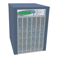
Gamatronic power+ sa User Manual (94 pages)
DOUBLE CONVERSION UPS TRUE ON-LINE BATTERY 10 kVA, 3x208 V
Brand:
Gamatronic
| Category:
UPS
| Size: 4.26 MB
Table of Contents
Table of Contents
3
1 Safety Precautions
7
Do's
7
Don'ts
9
2 General Features
12
Figure 2-1: Block Diagram of the POWER+ UPS
12
Figure 2-2: Control Panel
14
Figure 2-3: the LCD Screen Displays Real-Time Readings
15
Battery Check
16
Connections
16
Log
16
UPS Communications (Optional)
16
Measurement
15
Power-On Self Tests
15
Real Time
15
Major Subsystems
13
Charger
13
Batteries
13
Inverter
13
Static Switch (ST.SW. BYPASS)
13
Control System
14
Control Panel
14
3 Operating Modes
17
Figure 3-1: Normal Mode Display
17
Figure 3-2: Battery Mode Display
18
Bypass Mode
19
Normal Mode
17
Battery Mode
18
Figure 3-3: Bypass Mode Display
19
4 User Interface
20
Control Panel
20
Figure 4-1: the POWER+ SA Control Panel
20
The POWER + SA Display Screen
22
The Main Screen
22
Figure 4-3: Battery Test Failure
23
Figure 4-2: UPS On, Normal Mode
23
Status Screens
31
The POWER + SA Main Menu
37
Table 4-1: Main Menu Options
38
5 Daily Operation
39
6 The Event Log
41
7 Battery Tests
48
8 First-Time Setup
49
Cable Connections
49
Installation and Start-Up Sequence
50
9 Setting System Parameters
52
Setting the System Clock
52
Setting Screen Contrast
53
Modifying the Output Ac Voltage
54
To Change the Nominal Output Ac Voltage
54
To Adjust (Fine Tune) the Ac Output Voltage
55
Setting the DC Voltage
56
10 Bypass Option Activation / Deactivation
58
11 Automatic Restart
60
12 Miscellaneous Functions
62
13 In the Event of an Ac Power Outage
64
14 Troubleshooting
67
15 Installation and Setup
68
External Inspection
68
Site Preparations
68
Installation Considerations
69
Equipment Location
69
Site Connection Diagram
69
Figure 15-1: Site Connection Block Diagram
69
Elect R Ical Wiring
70
Table 15-2: Required Wire Ratings
70
Table 15-3: UL-Required Circuit Breaker Ratings
70
Figure 15-2: UPS Rear Panel with Protective Cover
72
Figure 15-3: UPS Rear Panel View, with Protective Cover Removed
73
Battery Installation
75
Table 15-1: Electrical Ratings and External Wiring Requirements
70
Installation Process
71
Safety Guidelines
71
Installing the POWER + SA
72
Figure 15-6: Battery Box, Front View, Front Cover Removed
75
Figure 15-5: Battery Box - Front View
75
Figure 15-4: Batterybox - Front Right View
75
Figure 15-7: Battery Box Circuit Breaker and Terminals
76
Figure 15-8: Battery Terminals on the POWER + SA Rear Panel
76
Verifications Prior to First-Time Operation
77
First-Time Startup and Verification Test
78
16 Alarm Dry Contacts
80
17 Rs232 Interface
82
18 Snmp Agent (Optional)
83
19 Wireless Control (Optional)
84
Figure 19-1: WING General Block Diagram
84
Table 20-1: 2- and 3-Phase Configuration - Electrical Details
87
Input and Output Wiring for Two-Phase Operation
89
20 Configuring the Power+ Sa for 2- and 3-Phase Usage
87
Figure 20-1: Wiring Diagram
87
Figure 20-2: Wiring Overview for Symmetrical 2-Phase Operation
89
Installing the P OWER + SA for 2-Phase Usage........................................84
90
Figure 20-3: UPS Rear Panel with Protective Cover
90
Figure 20-4: UPS Rear Panel View, with Protective Cover Removed
91
21 Power+ Sa Specifications
93
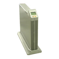
Gamatronic power+ sa User Manual (74 pages)
10 KVA DOUBLE CONVERSION UPS
Brand:
Gamatronic
| Category:
UPS
| Size: 2.56 MB
Table of Contents
Table of Contents
3
Conventions Used in this Book
5
Attaching the Power + Sa
6
To Its Base
6
Safety Considerations
7
Do's
7
Don'ts
7
Introduction
9
Major Parts of the POWER+ SA
10
Control Panel
10
Charger
10
Inverter
11
Static Switch (ST/SW)
11
Battery
11
Operating Modes
12
Normal Mode
12
Battery Mode
13
Bypass Mode
13
User Interface
15
Control Panel
15
On/Off Button
16
Navigation Keypad
16
Indicators
16
The POWER+ Display Screen
17
The Main Screen
17
Normal Mode
19
Battery Mode
21
Bypass Mode
24
UPS off
25
Status Screens
27
UPS Profile Screens
27
AC Output Screen
28
AC Input Screen
29
Bypass Screen
29
Inverter SCREEN
30
Battery SCREEN
31
The Power + SA Main Menu
32
Daily Operation
33
POWER + SA Start-Up
33
POWER + SA Shutdown
34
The Event Log
35
Alarms
35
Navigating to the Event Log
35
Active Alarm Display
35
Event Log Entries
36
Resetting the Event Log
36
Battery Tests
40
Automatic Battery Test
40
Manual Battery Test
40
First
41
Setup
41
Cable Connections for 3-3 Usage
41
Cable Connections for 3-1 Usage
44
Cable Connections for 1-1 Usage
48
Installation and Start-Up Sequence
51
To Start the UPS
51
Verify Proper Number of Input and Output Phases
51
Set the Output Voltage
51
Set the System Clock
52
Modify the Screen Contrast (Optional)
52
Set Automatic Restart Mode (Optional)
52
Operation
52
Setting System Parameters
53
Setting the System Clock
53
Setting Screen Contrast
54
Changing the Nominal Output Voltage
55
Fine-Tune the Output Voltage
56
Automatic Restart
58
Determining the Current Automatic Restart Setting
58
Changing the Automatic Restart Status
58
Miscellaneous Functions
60
Manually Entering or Leaving Bypass Mode
60
I N the Event of an Ac Power Outage
62
Troubleshooting
65
Alarm Sounds And/Or Alarm LED Lights up
65
Electricity Returned but UPS Remains in Battery Mode
65
Battery Test Failed
65
The UPS Remains in Bypass Mode
65
Sync Fault
65
Alarm Dry Contacts
66
Rs232 Interface
68
Snmp Agent (Optional )
69
Wireless Control ( Optional )
70
WING Configurations
71
Power+ Sa Specifications
73
Advertisement
Advertisement
Related Products
Gamatronic Power+
Gamatronic POWER+ PREMIUM
Gamatronic POWER PLUS
Gamatronic POWER Plus Premium SA 15
Gamatronic B60US-IB
Gamatronic Centric 100 kVA
Gamatronic CENTRIC 100 kW
Gamatronic Centric 120 kW
Gamatronic Centric 125 kVA
Gamatronic Centric 150 kVA
Gamatronic Categories
UPS
Measuring Instruments
Server
More Gamatronic Manuals
Login
Sign In
OR
Sign in with Facebook
Sign in with Google
Upload manual
Upload from disk
Upload from URL