Sign In
Upload
Manuals
Brands
Fuji Electric Manuals
Inverter
FRENIC-AQUA series
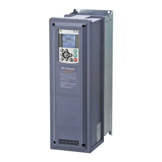
Fuji Electric FRENIC-AQUA series Manuals
Manuals and User Guides for Fuji Electric FRENIC-AQUA series. We have
2
Fuji Electric FRENIC-AQUA series manuals available for free PDF download: User Manual
Fuji Electric FRENIC-AQUA series User Manual (751 pages)
Brand:
Fuji Electric
| Category:
DC Drives
| Size: 23 MB
Table of Contents
Table of Contents
8
Chapter 1 ABOUT FRENIC-AQUA
16
Features
16
Inspection of Goods and Product Appearance
29
Inspection of Goods
29
Product Appearance
31
Chapter 2 SPECIFICATIONS
36
Standard Model
36
Frenic-Aqua
36
Common Specifications
39
Terminal Specifications
45
Terminal Functions
45
Setting up the Slide Switches
55
Screw Specifications and Recommended Wire Sizes
57
Main Circuit Terminals
57
Control Circuit Terminals (Common to All Inverter Types)
64
Cable Glands or Conduits
65
Cable Glands
65
Conduits
69
Leakage Current of the EMC Filter
72
Derating of Rated Output Current
74
Operating Environment and Storage Environment
75
Operating Environment
75
Storage Environment
76
Temporary Storage
76
Long-Term Storage
76
Precautions for Using Inverters
77
Precautions in Introducing Inverters
77
Precautions in Running Inverters
81
Precautions in Using Special Motors
81
External Dimensions
82
Standard Models
82
Keypad
88
Connection Diagrams
89
Chapter 3 SELECTING OPTIMAL MOTOR and INVERTER CAPACITIES
96
Selecting Motors and Inverters
96
Motor Output Torque Characteristics
96
Selection Procedure
98
Equations for Selections
101
Load Torque During Constant Speed Running
101
1 ] General Equation
101
2 ] Obtaining the Required Force F
101
Calculation of Acceleration/Deceleration Time
102
1 ] Calculation of Moment of Inertia
102
2 ] Calculation of the Acceleration Time
104
3 ] Calculation of the Deceleration Time
104
Heat Energy Calculation of Braking Resistor
105
1 ] Calculation of Regenerative Energy
105
2 ] Calculation of Energy Able to Regenerate Per Inverter
105
Chapter 4 SELECTING Peripheral EQUIPMENT
108
Configuring the FRENIC-AQUA
108
Selecting Wire Size
109
Currents Flowing Across the Inverter Terminals
109
Recommended Wires
110
Peripheral Equipment
112
Molded Case Circuit Breaker (MCCB), Residual-Current-Operated Protective Device (Rcd)/Earth Leakage Circuit Breaker (ELCB) and Magnetic Contactor (MC)
112
1 ] Functional Overview
112
2 ] Connection Example and Criteria for Selection of Circuit Breakers
113
Surge Killers for L-Load
115
Arresters
116
Surge Absorbers
117
Options
118
Selecting Peripheral Equipment Options
118
Power Regenerative PWM Converters, RHC Series
118
1 ] Overview
118
2 ] Specifications
119
3 ] Function Specifications
120
4 ] Converter Configuration
125
5 ] Basic Connection Diagrams
126
6 ] External Dimensions
128
AC Reactors (Acrs)
138
DC Reactors (Dcrs) (Built-In or Bundled as Standard)
142
Surge Suppression Unit (SSU)
144
Output Circuit Filters (Ofls)
145
Zero-Phase Reactors for Reducing Radio Noise (Acls)
148
Selecting Options for Operation and Communication
149
External Frequency Command Potentiometer
149
Extension Cable for Remote Operation
150
Frequency Meters
150
Inverter Support Loader Software (Available Soon)
151
Selecting Option Cards
152
List of Option Cards, Connection Ports, and Applicable ROM Versions
152
Relay Output Interface Card (OPC-RY)
153
Relay Output Interface Card (OPC-RY2)
155
Analog Interface Card (OPC-AIO)
157
Analog Current Output (2 Ch) Interface Card (OPC-AO)
161
Resistance Temperature Detectors Input Card (OPC-PT) (Available Soon)
162
CC-Link Communications Card (OPC-CCL)
163
PROFIBUS-DP Communications Card (OPC-PDP2)
165
Devicenet Communications Card (OPC-DEV)
168
Canopen Communications Card (OPC-COP)
171
LONWORKS Communications Card (OPC-LNW) (Available Soon)
173
Ethernet Communications Card (OPC-ETH) (Available Soon)
173
Backup Battery
174
Outline
174
Loading the Battery
175
Battery Loading Procedure
175
Battery Replacement Procedure
177
About Air Transport of Batteries
177
Chapter 5 PREPARATION and TEST RUN
180
Mounting and Wiring the Inverter
180
Installing the Inverter
180
Wiring
181
Removing and Mounting the Front Cover and the Wiring Plate
181
Screw Specifications and Recommended Wire Sizes
183
Main Circuit Terminals
183
Control Circuit Terminals (Common to All Inverter Types)
183
Cable Glands or Conduits
183
Wiring Precautions
184
Wiring of Main Circuit Terminals and Grounding Terminals
185
Wiring for Control Circuit Terminals
188
Setting up the Slide Switches
191
USB Port
192
Mounting and Connecting a Keypad
193
Parts Required for Connection
193
Mounting Procedure
193
Operation Using the Keypad
196
LCD Monitor, Keys and LED Indicators on the Keypad
196
Overview of Operation Modes
200
Running Mode
201
Monitoring the Running Status
201
Setting up Frequency and PID Commands
204
Running/Stopping the Motor
208
Remote and Local Modes
208
Changing from Keypad Operation to External Signal (Terminal Block) Operation
209
Monitoring Light Alarms
209
Programming Mode
210
Quick Setup
212
Start-Up
212
Set Display Language
213
Function-Specific Initialization
214
Date/Time Settings
214
Set Display
217
Function Codes
217
Function Codes
218
Setting up Function Codes
219
Confirm Data
221
Confirm Changed Function Code
221
Copying Data
221
Set Timer Operation
233
Initialize Data
236
Inverter Information
237
Confirm Power Level
237
Confirm Operational Status
238
Check Status of Input/Output Signal
241
View Maintenance Information
243
View Unit Information
247
Alarm Information
248
Confirm Alarm History
248
Confirm Light Alarm History
252
Retry History
252
User Config
253
Quick Setup
253
Password
253
Tools
257
Monitor PID Control Status
257
Monitor Multiple Unit Controls
260
Monitor Customized Logic (Clogic)
263
Resonance Avoidance
264
Load Factor Measurement
265
Communication Debug
268
Alarm Mode
269
Releasing the Alarm and Switching to Running Mode
269
Displaying the Alarm History
269
Displaying the Status of Inverter at the Time of Alarm
269
Test Run Procedure
270
Checking Prior to Powering on
271
Powering on and Checking
272
Selecting a Desired Motor Drive Control
272
Function Code Basic Settings < 1
273
Function Code Basic Settings and Tuning < 2
274
Running the Inverter for Motor Operation Check
276
Preparation for Practical Operation
277
Chapter 6 FUNCTION CODES
282
Overview of Function Codes
282
Function Code Tables
283
Details of Function Codes
325
F Codes (Fundamental Functions)
325
E Codes (Extension Terminal Functions)
367
C Codes (Control Functions)
411
P Codes (Motor 1 Parameters)
423
H Codes (High Performance Functions)
427
H1 Codes (High Performance Functions)
470
J Codes (Application Functions 1)
477
J1 Codes (PID Control 1)
478
J2 Codes (PID Control 2)
518
J4 Codes (Pump APP Functions)
520
J5 Codes (External PID Control 1)
560
J6 Codes (External PID Control 2, 3)
584
D Codes (Application Functions 2)
588
U Codes (Customizable Logic Functions)
589
U1 Codes (Customizable Logic Functions)
610
Y Codes (Link Functions)
615
T Codes (Timer Functions)
620
K Codes (Keypad Functions)
624
Chapter 7 BLOCK DIAGRAMS for CONTROL LOGIC
640
Symbols Used in Block Diagrams and Their Meanings
640
Frequency Command Block
641
Drive Command Block
643
V/F Control Block
644
PID Process Control Block
646
External PID Process Control Block
648
FM1/FM2 Output Selector
650
Chapter 8 RUNNING through RS-485 COMMUNICATION
654
Overview on RS-485 Communication
654
Common Specifications
655
Terminal Specifications for RS-485 Communication
656
Connection Method
657
Communications Support Devices
659
Noise Suppression
660
Overview of FRENIC Loader
661
Specifications
661
USB Port on the Inverter Unit
662
Chapter 9 TROUBLESHOOTING
666
Protective Functions
666
Before Proceeding with Troubleshooting
667
If an Alarm Code Appears on the Monitor
668
Alarm Codes
668
If the "Light Alarm" Indication Appears
686
Nothing Appears on the Monitor
688
Abnormal Motor Operation
688
Problems with Inverter Settings
695
If Other than an Alarm Code Is Displayed
697
Chapter 10 MAINTENANCE and INSPECTION
700
Daily Inspection
700
Periodic Inspection
700
List of Periodic Replacement Parts
702
Judgment on Service Life
703
2 ] Measuring the Capacitance of the DC Link Bus Capacitor under Ordinary Operating Conditions
705
3 ] Early Warning of Lifetime Alarm
706
Measurement of Electrical Amounts in Main Circuit
707
Insulation Test
708
Cooling Fan Replacement Procedure
709
Chapter 11 CONFORMITY with STANDARDS
720
Compliance with European Standards
720
Conformity to the Low Voltage Directive in the EU
721
Compliance with EMC Standards
724
General
724
Recommended Installation Procedure
724
Leakage Current of the EMC Filter
726
Harmonic Component Regulation in the EU
728
General
728
Compliance with IEC/EN 61000-3-2
728
Compliance with IEC/EN 61000-3-12
728
Conformity with UL Standards and CSA Standards (Cul-Listed for Canada) (under Application)
729
General
729
Conformity with UL Standards and CSA Standards (Cul-Listed for Canada)
729
Appendices
732
App. a Advantageous Use of Inverters (Notes on Electrical Noise
734
Effect of Inverters on Other Devices
734
Noise
734
Noise
735
Noise Prevention
737
App. B Effect on Insulation of General-Purpose Motors Driven with 400 V Class Inverters
745
Generating Mechanism of Surge Voltages
745
Effect of Surge Voltages
746
Countermeasures against Surge Voltages
746
Regarding Existing Equipment
747
App. C Inverter Generating Loss
748
Advertisement
Fuji Electric FRENIC-AQUA series User Manual (190 pages)
RS-485 Communication
Brand:
Fuji Electric
| Category:
Inverter
| Size: 4 MB
Table of Contents
Table of Contents
6
Safety Precautions
5
Chapter 1 Overview
10
Features
10
List of Functions
12
Chapter 2 Common Specifications
16
Specifications of RS-485 Communications
16
RJ-45 Connector (Modular Jack) Specifications
18
Terminal Block Specifications
19
Connection Cable Specifications
20
Connections
21
Connection Notes
25
Connection Devices
28
Measures against Noise
29
Switching to Communications
31
Link Functions (Mode Selection)
32
How to Switch Communications Enabled/Disabled
33
Loader Link Functions (Mode Selection)
34
Making RS-485-Related Settings
35
Selecting Data Clear Processing for Communications Error
38
CHAPTER 7 Bacnet MS/TP
40
Messages
40
CHAPTER 6 Metasys N2 (N2 PROTOCOL)
42
Messages
42
CHAPTER 3 Modbus RTU PROTOCOL
43
Message Frames
43
Message Categories
45
Communications Examples
53
Host Side Procedures
54
Timeout Processing
55
Receiving Preparation Complete Time and Message Timing from the Host
56
Communications Errors
57
Operations in Case of Errors
58
Crc-16
61
Calculation Example
63
Frame Length Calculation
64
Descriptions of Fields
66
Communications Examples
80
Chapter 5 Function Codes and Data Formats
88
Communications Dedicated Function Codes
88
Command Data
89
Monitor Data 1
98
Information Displayed on the Keypad
103
Data Formats
119
Data Format Specifications
150
Metasys N2 (N2 Protocol)
168
Chapter 4 Fuji General-Purpose Inverter Protocol
168
Messages
168
Messages
170
Communications Specifications
170
Polling/Selecting
170
Setting up the FRENIC-HVAC/AQUA
171
Point Mapping Tables
172
Reading and Writing From/To Function Codes
174
Support Command Lists
175
Communications Specifications
182
Messages
182
Setting up the FRENIC-HVAC/AQUA
183
Binary Point Table
184
Analog Point Table
186
Reading and Writing From/To Function Codes
187
Advertisement
Related Products
Fuji Electric FRENIC-Ace series
Fuji Electric Frenic-Mini
Fuji Electric Frenic Mega Series
Fuji Electric frenic mini series
Fuji Electric FRENIC-Eco Series
Fuji Electric Frenic lift
Fuji Electric FRENIC-VG Series
Fuji Electric FRENIC5000 G5 Series
Fuji Electric FRENIC5000 P9S Series
Fuji Electric FRENIC5000 P7 Series
Fuji Electric Categories
Air Conditioner
Inverter
Measuring Instruments
Controller
Control Unit
More Fuji Electric Manuals
Login
Sign In
OR
Sign in with Facebook
Sign in with Google
Upload manual
Upload from disk
Upload from URL