Sign In
Upload
Manuals
Brands
Fuji Electric Manuals
Inverter
Frenic lift
Fuji Electric Frenic lift Manuals
Manuals and User Guides for Fuji Electric Frenic lift. We have
3
Fuji Electric Frenic lift manuals available for free PDF download: Reference Manual, Starting Manual
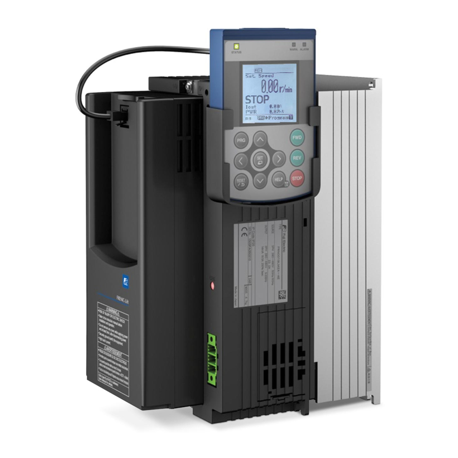
Fuji Electric Frenic lift Reference Manual (255 pages)
Brand:
Fuji Electric
| Category:
DC Drives
| Size: 5 MB
Table of Contents
Chapter 1 BLOCK DIAGRAMS for CONTROL LOGIC
4
Icons
4
Table of Contents
5
Block Diagrams for Control Logic
6
Symbols Used Inside the Block Diagrams and Their Meanings
8
Reference Speed (Pre-Ramp) Command Generator
9
Reference Torque Command Generator
10
Drive Command Controller
11
Function Codes
12
Changing/Validating/Saving Function Code Data When Inverter Is Running
14
Copying Data
14
Function Code Tables
14
Control Mode
15
Using Negative Logic for Programmable I/O Terminals
15
Corresponding Software Version
16
F Codes: Fundamental Functions
17
E Codes: Extension Terminal Functions
18
C Codes: Control Functions
21
P Codes: Motor Parameters
22
H Codes: High Performance Functions
23
U Codes: Application Functions (Customizable Logic)
25
Y Codes: Link Functions
28
L Codes: Lift Functions
30
Default Table
34
K Codes: Keypad Functions (Optional)
34
Before Setting the Function Code
35
Symbols Definition
35
Overview of Function Codes
36
Data Protection (F00)
37
F Codes (Fundamental Functions)
37
Password Protection (H99)
37
Combining SS1, SS2, and SS4 with Reference Speeds (Pre-Ramp)
38
Definition of Setting Value for L11 to L18
39
Acceleration/Deceleration Times in S-Curve Operation
42
Low Speed
43
Middle Speed
43
Operation Examples
43
High Speed
44
Manual Speed
44
Creep Speed to Stop
45
Manual Speed (Middle)
45
Analog Multistep Speed Command
46
Analog Speed Command
46
Rated Speed
47
Acceleration/Deceleration Time 1, 2
48
Base Speed
48
Rated Voltage
48
Electronic Thermal Overload Protection for Motor
49
Select Motor Characteristics (F10)
49
Torque Boost
49
Characteristics in F10=1
50
Characteristics in F10=3
50
Overload Detection Level
50
Thermal Time Constant
50
DC Braking(Operation Level)
52
DC Braking(Operation Time)
52
DC Braking(Starting Speed)
52
Soft Start Time (H65)
53
Starting Speed
53
Starting Speed (Holding Time)
53
Zero Speed Control Time (H64)
53
In Case of Vector Control with PG
54
Speed Start Mode
54
Start Control Mode (L52)
54
When an Analog Speed Command (Not Reversible) Is Enabled
55
When an Analog Speed Command (Reversible) Is Enabled
55
In Case of Torque Vector Control
56
Torque Start Mode
56
Detection Method (H66)
58
Holding Time (H67)
58
Stop Speed
58
Analog Output [FMA] (Output Gain, Function Selection)
59
Motor Sound (Carrier Frequency)
59
Function Selection (F31)
60
Braking Load (Kw)
61
Current Limiter (Level)
61
Electronic Thermal Overload Protection for Braking Resistor
61
Allowable Average Loss (F51)
62
Braking Resistance Value (F52)
62
Discharging Capability (F50)
62
E Codes (Extension Terminal Functions)
63
Coast to a Stop -- BX
64
Reset Alarm -- RST
64
Select Multistep Speed -- SS1, SS2,SS4 and SS8
64
Terminal Function Assignment and Data Setting
64
Enable Communications Link Via RS485 or CAN
65
Enable External Alarm Trip
65
Enable Jogging Operation
65
Enable PG Vector Control
65
Check Brake Control
66
Force to Decelerate
66
Magnetic Pole Position Offset Tuning Command -- PPT
66
Start Creepless Operation
66
No Function Assigned – “NONE”
67
Run Forward – “FWD”
67
Run Reverse – “REV”
67
Start Reference Torque Decreasing – RTDEC
67
Enable Rescue Operation by Means of Brake Control
68
Short-Circuit Control Feedback – SCCF
68
Stand-By Mode – STBY
68
Unlocking Safty Gear Operation – ULSG
69
Acceleration/Deceleration Time 3 to 10
70
Application of the Agreement Timer
70
Run Command/Multistep Speed Command Agreement Timer (Mode)
70
Run Command/Multistep Speed Command Agreement Timer (Time)
70
Signal Assignment to [Y1] to [Y2] (Transistor Signal)
71
Inverter Running – RUN
74
Speed Arrival – FAR
74
Speed Detected – FDT
74
Speed Detected – FDT2
74
Auto-Resetting – TRY
75
Overheat Early Warning – OH
75
Service Life Alarm – LIFE
75
Universal DO – U-DO
75
Encoder Rotating in Forward Direction – “FRUN”
76
Encoder Rotating in Reverse Direction – “RRUN"
76
Motor Overheat Detected (PTC) – THM
76
Run Command Activated – AX2
76
During Zero Speed – DZR
77
Speed Agreement – DSAG
77
Speed Arrival 3 – FAR3
77
Speed Existence – DNZS
77
Drive Continuance Alarm – ALM2
78
Electric Angle Cycle – EAC
78
Low Voltage Detected – LVD
78
Magnetic Pole Position Offset Tuning – DTUNE
78
Input Power Limitation – IPL
79
MC Control 2 – SW52-3
79
Pole Tuning Done – PTD
79
Detected Speed Direction – DSD
80
Short-Circuit Control – SCC
80
Travel Direction Changes Lifetime Early Warning – TDCL
80
Travel Direction Changes Pulse – TDCP
80
Deliverance Operation Calculation End – CEND
81
Loadcell Full Load Detection – LCF
81
Loadcell LV1 Detection – LC1
81
Loadcell Overload Detection – LCO
81
Output Signals "Speed Arrival FAR"
82
Speed Arrival (Hysteresis)
82
Speed Detection (FDT) (Detection Level)
83
Speed Detection (FDT) (Hysteresis)
83
Speed Detection Hysteresis (E32)
83
Speed Detection Level (E31 or E36)
83
Current Detection 1 (Level 1)
84
Current Detection 1 (Time)
84
Current Detection 2 (Level 2)
84
Speed Detection 2 (FDT) (Detection Level)
84
LED Monitor (Item Selection)
85
LED Monitor (Speed Monitor Item) (E48)
85
Keypad (Menu Display Mode)
86
Terminal [V2] Function Selection (C1 Function//V2 Function)
86
Analog Input for [12] (Extension Function Selection)
87
Analog Input for [V2] (C1 Function) (Extension Function Selection)
87
Analog Input for [V2] (V2 Function) (Extension Function Selection)
87
Command Assignment to [FWD]
88
Command Assignment to [REV]
88
Battery Operation (Limit Level)
89
Battery Operation (Limit Time)
89
Battery Operation Speed
89
C Codes (Control Functions)
89
Delay Time from BATRY on to 73X on
90
Requirements for Battery Operation
90
Connection Diagram in Case of Batteries and FRN0032LM2A-4
91
Connection Diagram in Case of Batteries and FRN0039LM2A-4_ or above
91
Connection Diagram in Case of UPS
91
Operation Time Diagram
92
Precautions
92
Jogging Operation Speed
93
Multistep Speed
93
Analog Input Type
94
Relational Equations between (Hz) and Other Units
94
Speed Command Unit
94
Analog Input Adjustment for [12] (Offset) (Gain)
95
Analog Input Adjustment for [V2] (C1 Function) (Offset) (Gain)
95
Command Values
95
Data Setting Range
96
Filter Time Constant (C33, C38, and C43)
96
Motor (No. of Poles)
97
Motor (Rated Capacity)
97
Motor (Rated Current)
97
P Codes (Motor Parameters)
97
Motor (Auto-Tuning)
98
Motor (%R1)
99
Motor (%X)
99
Motor (No-Load Current)
99
Motor (Rated Slip)
100
Motor (Slip Comp. Braking Gain)
100
Motor (Slip Comp. Driving Gain)
100
Motor (Slip Comp. Response Time)
100
Data Initialization
101
H Codes (High Performance Functions)
101
Initialize All Function Code Data to Factory Defaults
101
Initialize Customizable Logic U/U1 Code Data
101
System-Specific Initialization
102
Auto-Reset (Reset Interval)
103
Auto-Reset (Times)
103
Number of Auto-Reset Times (H04)
103
Reset Interval (H05)
103
Alarm Codes Crossreference with H82 Bits
104
Auto Reset (Mode Selection 1) (H81)
104
Auto Reset (Mode Selection 2) (H82)
104
Cooling Fan Control
104
PTC / NTC Thermistor (Level)
105
PTC / NTC Thermistor (Mode)
105
Command Sources Selectable
106
Communications Link Operation
106
Capacitance of DC Link Bus Capacitor
107
Cumulative Run Time of Capacitors on Printed Circuit Board
107
Cumulative Run Time of Cooling Fan
107
Initial Capacitance of DC Link Bus Capacitor
107
Acceleration Time (Jogging)
108
Deceleration Time (Jogging)
108
Deceleration Time for Forced to Decelerate
108
Forced to Decelerate
108
S-Curve Setting 10 to 14
109
Starting Speed (Soft Start Time)
109
Stop Speed (Detection Method)
109
Zero Speed Control Time
109
Main Power Shutdown Detection (Mode Selection)
110
Speed Agreement (Hysteresis)
110
Speed Agreement (off Delay Time)
110
Output Current Fluctuation Damping Gain
111
PG Error Detection for Mode 3 (Detecting Time)
111
PG Error Detection for Mode3 (Detecting Level)
111
Store Electronic Thermal Overload Protection Data for Motor
111
Brakes Monitor According to UCM (Check Brake Control Select)
112
Brakes Monitor According to UCM (Clear Bbe Alarm)
112
Brakes Monitor According to UCM (Check Brake Control Select) (H96)
113
Brake Feedback Not Matching with Brake Control Signal at Stop
114
Brake Feedback Not Matching with Brake Control Signal During Travel
114
Brake Feedback Is Abnormal When Motor Is Stopped
115
Alarms and SUB Codes
116
Brakes Monitor According to UCM (Clear Bbe Alarm) (H95)
116
Clear Alarm Data
117
Protection/Maintenance Function
117
Detect Input Phase Loss
118
Detect Output Phase Loss (OPL)
118
Lower the Carrier Frequency Automatically
118
Multistep Speed Command
118
Analog Speed Command (Not Reversible)
119
Analog Speed Command (Reversible)
119
Select Life Judgment Criteria of DC Link Bus Capacitor
119
Vector Control with PG
119
Braking Transistor Error Detection (Bit 6)
120
Canceling Detection of Thermistor Cut Line (Bit 7)
120
Judge the Life of DC Link Bus Capacitor (Bit 4)
120
Password Protection
120
Modes
121
U Codes (Customizable Logic Operation)
121
Block Diagram
122
Block Selection (U01, U06, U11, Etc.)
123
Customizable Logic (Mode Selection) (U00)
123
Customizable Logic (Mode Setting) (U01 to U70, U190 to U195)
123
Block Function Code Setting
125
Block Selection (U01, U06, Etc.) (Digital)
125
Logical and
126
Logical or
126
Logical XOR
126
Through Output
126
Falling Edge Detector
127
Hold
127
Rising & Falling Edges Detector
127
Rising Edge Detector
127
Off-Delay Timer
128
On-Delay Timer
128
One-Shot Pulse Output
128
Operation of General-Purpose Timer(Digital)
128
Inputs 1 and 2 (U02, U03, U07, U08, Etc.)(Digital)
129
Block Selection, Function 1, Function 2
130
Function 1 (U04, U09, Etc.)(Digital)
130
Adder
133
Divider
133
Inverting Adder
133
Limiter
133
Comparator 6
134
High Selector
134
Low Selector
134
Window Comparator
134
[Input: Digital, Analog] Block Function Code Setting
136
Inverting Adder with Enable
139
Low Pass Filter with Enable
139
Rate Limiter with Enable
139
Selector
139
Output Signals (Digital,Analog)
140
Specific Function Codes
142
Configuration of Function Codes
143
Function Codes for the Customizable Logic
143
Task Process Cycle Setting (U100)
143
Customizable Logic Timer Monitor (Step Selection) (U91, X89 to X93)
144
Monitor Method
144
Operating Precautions
144
Selection of Monitor Timer
144
Cancel Customizable Logic “CLC”
145
Clear All Customizable Logic Timers “CLTC”
145
Inverter Supporting Loader (FRENIC Loader)
146
RS-485 Communication Setting 1 and 2
146
Station Addresses (Y01, Y11)
146
Y Codes (Link Functions)
146
Baud Rate (Y04, Y14)
147
Communications Error Processing (Y02, Y12)
147
Data Length Selection (Y05, Y15)
147
Error Process Timer (Y03, Y13)
147
Communication Time-Out Detection Timer (Y08, Y18)
148
Protocol Selection (Y10, Y20)
148
Response Interval Time (Y09, Y19)
148
Stop Bit Selection (Y07, Y17)
148
Baud Rate (Y24)
149
Built-In Canopen Communication Setting
149
Node-ID (Y21)
149
User-Defined I/O Parameter 1 to 8
149
Communication Time-Out Detection Timer (Y35)
150
Communications Error Processing (Y34)
150
Operation Selection in Abort Status (Y36)
150
Communication Data Storage Selection
151
Compatibility Selection (Y37)
151
Setting Method of Speed Command by Communication
151
Bus Function (Mode Selection)
152
Loader Link Function (Mode)
152
L Codes (Lift Functions)
153
Pulse Encoder (Resolution)
153
Pulse Encoder (Selection)
153
Magnetic Pole Position Offset (Offset Angle)
154
Magnetic Pole Position Offset (Tuning)
154
ACR I Constant
155
ACR P Constant
155
Automatic Pole Tuning Selection
155
Tuning Procedure When L03 = "4: Tuning with Motor Stopped"
155
Filter Time Constant for Detected Speed
157
Filter Time Constant for Reference Speed (Final)
157
Multistep Speed Command Combination (Zero Speed to High Speed)
157
S-Curve Setting 1 to 10
157
Elevator Parameter (over Speed Protection Level)
160
Elevator Parameter (over Speed Timer)
160
Elevator Parameter (Speed)
160
Creepless Operation
161
Elevator Parameter (Moving Distance in Creepless Operation)
161
Requirements for Creepless Operation
161
Conditions Required for Starting a Creepless Operation
162
Deceleration Point Programming and Moving Distance
162
Example of Creepless Operation with CRPLS
163
Input Timing of a Creepless Operation Command
163
Restrictions on Creepless Operation
163
Example of Creepless Operation Without CRPLS
164
Improving the Landing Position Accuracy in a Creepless Operation
164
ASR (I Constant at High Speed)
165
ASR (P Constant at High Speed)
165
ASR (P Constant at Low Speed)
165
Notes for Accurate Landing in a Creepless Operation
165
ASR (Feed Forward Gain)
166
ASR Switching Speeds (L40 and L41)
166
Integral Time (L50)
167
Vibration Suppression Observer (Gain)
167
Vibration Suppression Observer (Integral Time)
167
Vibration Suppression Observer (Load Inertia)
167
Block Diagram of Torque Bias Generator
168
Torque Bias (L54)
168
Torque Bias (Mode)
168
Analog Torque Bias (L54 = 0)
169
Balancing
169
Gain Adjustment
169
DCP Torque Bias
170
Digital Torque Bias (L54 = 1)
170
PI Torque Bias (L54 = 2)
170
Terminal Command "Hold Torque Bias" and Startup Time
171
Torque Bias (Startup Time)
171
In Speed Control
172
Reference Torque End Sequence in Speed Control
172
Torque Bias (Reference Torque End Time)
172
Torque Bias (Driving Gain)
173
Torque Bias (I Constant)
173
Torque Bias (Limiter)
173
Torque Bias (P Constant)
173
Unbalanced Load Compensation (Operation)
174
Unbalance Load Compensation (APR D Constant)
176
Unbalanced Load Compensation (Activation Time)
176
Unbalanced Load Compensation (ASR I Constant)
176
Unbalanced Load Compensation (ASR P Constant)
176
Brake Control (Mode)
177
Brake Control (off Delay Time)
177
Brake Control (on Delay Time)
177
Brake Control (Operation Level)
177
Brake Check Time (L84)
178
Brake Confirmation Signal BRKE
178
Brake Control Signal BRKS
178
Brake Control Timing Schemes
179
MC Control (MC off Delay Time)
180
MC Control (Startup Delay Time)
180
MC off Delay Time (L86)
180
Startup Delay Time (L85)
180
MC Control 2 SW52-3
181
MC Control Signal 2 SW52-3 Timing Diagram
181
MC Control Signal SW52-2 Timing Diagram
181
MC Operation Confirmation
181
SW52-2 Timing Scheme
182
SW52-3 Timing Scheme
182
Door Control
183
Door Control (Door Open Delay Time)
183
Door Control (Door Open Period)
183
Door Control (Door Open Starting Speed)
183
PG Abnormal (Operation Choice)
184
PG Error Detection (Detection Level)
184
PG Error Detection (Detection Time)
184
Overheat Early Warning Level
185
Drive Continuance Alarm (Bit 1)
186
Magnetic Pole Position Tuning (Voltage)
186
Over Torque Current Protecting Operation (Bit 0)
186
Protecting Operation Selection Switch
186
Both Type of Alarms Occurrence
187
Drive Continuance Excluded Alarm Occurence
187
Drive Continuance Object Alarm Occurrence
187
Calculate ASR with Only Speed Command During ULC (Bit 4)
188
Current Confirmation for Synchronous Motor (Bit 0)
188
ENOFF Signal Output Mode (Bit 3)
188
FAN ON/OFF During Battery Operation (Bit 6)
188
Abnormal Operation
189
Initial Torque Bias and Reference Torque Decreasing (Bit 2)
189
Normal Operation
189
Reference Torque Decreasing
189
Description of Mode 2
190
Short Floor Operation Using S Curve (Bit 3)
190
DOPEN Function Change (Bit 6)
192
Rise Direction Definition for DCP (Bit 4)
192
S1 Bit Selection for DCP (Bit 5)
192
When L99 Bit6 Is 1
193
Unlock Safety Gear (Level)
194
Unlock Safety Gear (Operation)
194
Unlock Safety Gear (Pluse Time)
194
Unlock Safety Gear (Rest Time)
194
Encoder Rotation (Detection Speed)
195
Travel Direction Counter (Password Setting) (L109)
195
Travel Direction Counter (Password Unlock) (L110)
195
Travel Direction Counter (Travel Limit) (L111)
195
Travel Direction Counter (Partial Number of Direction Changes) (L113)
196
Travel Direction Counter (Warning Level) (L112)
196
Rescue Operation by Brake Control (Apply Time)
197
Rescue Operation by Brake Control (Speed Limit)
197
Travel Direction Counter
197
Travel Direction Counter (Total Number of Resets) (L115)
197
Rescue Operation by Brake Control (Apply Time) (L118)
198
Rescue Operation by Brake Control (Speed Detection Delay Time) (L119)
198
Rescue Operation by Brake Control (Speed Limit)(L117)
198
Timing Diagram When Limit Speed Is Not Reached
198
Timing Diagram When L117 Speed Level Is Reached
199
Inverter Locked by Rba (Case 2)
200
Short Circuit Control (Check Time)
200
Short Circuit Control (Control Mode)
200
Short Circuit Control (Check Time) (L121)
201
Short Circuit Control (Control Mode) (L120)
201
Standard Travel Timing Sequence with Feedback Contacts
201
Emergency Stop Timing Sequence
202
Starting Sequence with Feedback Contacts Timing Problem (SCA Alarm)
202
Feedback Problem During Normal Travel (SCA Alarm)
203
Inverter in Alarm (ALM Output Function ON)
203
Stopping Sequence with Feedback Contact Timing Problem
203
RBRK Input Function Is on
204
Rescue Operation by Brake Control
204
Deliverance Operation (Direction Calculation Delay Timer)
205
Deliverance Operation (Direction Calculation Setup)
205
Deliverance Operation (Input Power Detection Level)
205
STBY Input Function Is on
205
Direction Calculation Delay Timer (L124)
206
Direction Calculation Setup (L123)
206
Ups/Batteries Minimum Operation Level
206
Encoder Diameter (De)
208
Sheave Diameter (Ds)
208
Theta Compensation Band
208
Theta Compensation Gain Lower Limiter
208
Encorder Electronic Name Plate (EEPROM Bank Number)
209
Encorder Electronic Name Plate (Mode)
209
Load Cell Function (LC1 Detection Level)
209
Load Cell Function (Timer)
209
Level Detection 1 (LC1)
210
Load Cell Function (LC1 Detection Level) (L145)
210
Load Cell Function (Overload Mode Selection) (L143)
210
Load Cell Function (Timer) (L144)
210
Full Load Detection Level (LCF)
211
Load Cell Function (LCF Detection Level) (L146)
211
Load Cell Function (LCO Detection Level) (L147)
212
Overload Detection Level (LCO)
212
Overload Detection with LCO Alarm (L132=1)
213
TDC Lifetime Early Warning
213
Warning Selection Switch
213
Carrier Frequency Fixed
214
Ground Fault Detection Cancel
214
Masked Parameters Depending on Set Control Mode
214
Operation Setting Switch 1
214
K Codes (Keypad Functions)
215
LCD Monitor (Backlight Brightness Control)
215
LCD Monitor (Backlight off Time)
215
LCD Monitor (Language Selection)
215
LCD Monitor Status Display/Hide Selection
216
LCD on the Keypad
216
Sub Monitor (Display Type)
216
Sub Monitor 1 (Display Item Selection)
217
Sub Monitor 2 (Display Item Selection)
217
Bar Chart 1 (Display Item Selection)
218
Bar Chart 2 (Display Item Selection)
218
Bar Chart 3 (Display Item Selection)
218
Traveling Direction Selection
218
Operation Using “Tp-A1-Lm2”
220
Indication of LED Indicators
222
LCD Monitor, Keys and LED Indicators on the Keypad
222
Names and Functions of Keypad Components
222
LCD Monitor
224
Main Items Displayed on the LCD Monitor
224
Screen Example in Alarm Mode
224
Screen Example in Running Mode
224
Icons on the LCD Monitor
225
Running Status
225
Status Messages on the LCD Monitor
225
Travel Direction Indicator
225
Alarm Mode
226
Overview of Operation Modes
226
Programming Mode
226
Running Mode
226
Monitoring the Running Status
227
Running Mode
227
Switching Main Monitor Item (Display Example)
227
Remote and Local Modes
228
Setting up Reference Speed (Display Example)
228
Setting up Reference Speed (Pre-Ramp)
228
Available Speed Command Sources
229
Rotational Direction of Motor
229
Running/Stopping the Motor
229
Hierarchy Indicator
230
Menus Transition in Programming Mode
230
Menus Available in Programming Mode
231
Quick Setup
232
Select Application: “App Select”
232
Set Display Language: “Language”
232
Start-Up
232
Display Settings: “Disp Setting”
233
Items Available in Display Settings
233
Changing Function Code Data While Running
234
Double-Key Operation
234
Screen Transition Example for Setting Function Code
234
Setting up Function Code Data: “Data Set”
234
Checking Changed Function Code Data: Changed Data”
235
Checking Function Code Data: “Data Check”
235
Copying Function Code Data: Data Copy”
236
Operations Available in Copying Function Code Data
236
Checking Function Code Data Stored in Keypad (Display Example)
237
Screen Transition Example for Copying Function Code Data
237
Overwritten Protected Status (Display Example)
238
Overwritten Protection for Copied Data
238
Error Messages
239
Check Operational Status: “Op Monitor”
240
Initialization Types
240
Initialize Function Code Data: “Initialize”
240
Inverter Information: “INV Info”
240
Check Status of Input/Output Signal Status: “I/O Check”
243
Display Items in “I/O Check”
243
Screen Transition for “I/O Check” (Display Example)
243
Display Items in “Maintenance”
244
View Maintenance Information: “Maintenance”
244
Screen Transition for “Maintenance” (Display Example)
246
Unit Information Screen (Display Example)
246
View Unit Information: “Unit Info”
246
Alarm Information: “Alarm Info”
247
Check Alarm History: “Alarm History”
247
Check/Set Travel Direction Counter Function: “Travel Counter”
247
Programming Mode
248
Quick Setup
249
Screen Transition for “Alarm History” (Display Example)
249
User Configuration: “User Config”
249
Communication Debug: “COM Debug”
250
Load Factor Measurement: “Load Factor”
250
Monitor Customizable Logic: “Clogic Monitor”
250
Tools
250
Displaying the Alarm History
251
Displaying the Status of Inverter at the Time of Alarm
251
Releasing the Alarm and Switching to Running Mode
251
Advertisement
Fuji Electric Frenic lift Starting Manual (35 pages)
Dedicated Inverter for Lift Applications
Brand:
Fuji Electric
| Category:
Inverter
| Size: 1 MB
Table of Contents
Table of Contents
3
About this Manual
4
1 Safety Information
4
2 Conformity to European Standards
6
3 Technical Data
7
Specifications
7
External Dimensions
8
4 Removal and Attachment of
9
5 Connections
10
Power Connection
10
Control Signals Connection
11
Use of Input Terminals for Speed Set Point Selection
12
Control Terminals Description
12
6 Hardware Configuration
14
7 Encoder Option Boards
15
Opc
16
Opc-Pmpg
17
Opc-Pr
17
Opc-Psh
19
8 Keypad Operation
20
Keypad Keys
20
Keypad Menus
22
Example of Function Setting
23
Display Language Setting
23
9 Driving the Motor
24
Inverter Initialization
24
Specific Setting for Induction Motors (with Encoder)
24
Auto Tuning Procedure (for IM)
24
Specific Setting for PMS Motors
25
Pole Tuning Procedure (for PMS Motors)
25
10 Setting the Speed Profile
26
11 Signal Timing Diagram for Close Loop Control (IM and PMSM)
27
12 Signal Timing Diagram for Open Loop Control (IM)
28
13 Travel Optimization in Closed Loop
29
14 Lift Fine Tuning (Troubleshooting)
30
Open Loop Control (IM)
30
Closed Loop Control (PMSM and IM)
31
15 Alarm Messages
33
Fuji Electric Frenic lift Starting Manual (21 pages)
Starting guide for CAN CiA 417
Brand:
Fuji Electric
| Category:
DC Drives
| Size: 0 MB
Table of Contents
Table of Contents
3
Introduction
4
1 Connections
4
CAN Bus Terminal
4
Shield Connection
5
Terminal Resistor
5
2 Virtual Console
6
Virtual Console Keys
6
Virtual Console Menus
7
3 Basic Setting
10
4 Start-Up
12
5 Lift Speed Profile Settings
12
Velocity Mode
13
Profile Position Mode
14
6 Signals Timing Diagram for Close Loop Control (IM and PMSM)
16
7 Signal Time Diagram for Open Loop (IM)
17
8 Travel Optimization in Position Mode
18
9 Alarm Messages
20
Advertisement
Advertisement
Related Products
Fuji Electric FRENIC-Lift series
Fuji Electric FRENIC-MEGA
Fuji Electric FRENIC5000 P5 Series
Fuji Electric FRENIC5000 G7 Series
Fuji Electric FRENIC5000 P7 Series
Fuji Electric FRENIC-eHVAC
Fuji Electric FRENIC Series
Fuji Electric FRENIC5000 VG7S Series
Fuji Electric FRENIC5000 VG5 Series
Fuji Electric FRENIC5000 VG3 Series
Fuji Electric Categories
Air Conditioner
Inverter
Measuring Instruments
Controller
Control Unit
More Fuji Electric Manuals
Login
Sign In
OR
Sign in with Facebook
Sign in with Google
Upload manual
Upload from disk
Upload from URL