Sign In
Upload
Manuals
Brands
Fuji Electric Manuals
Inverter
FRENIC-VG Series
Fuji Electric FRENIC-VG Series Manuals
Manuals and User Guides for Fuji Electric FRENIC-VG Series. We have
2
Fuji Electric FRENIC-VG Series manuals available for free PDF download: User Manual
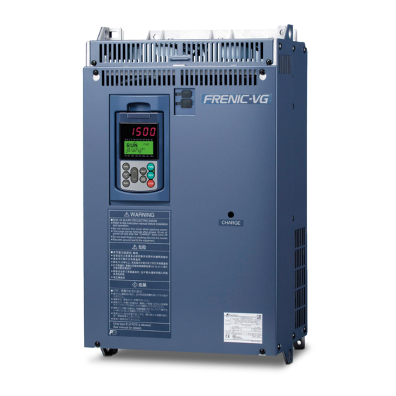
Fuji Electric FRENIC-VG Series User Manual (752 pages)
Unit Type/Function Codes Edition
Brand:
Fuji Electric
| Category:
Network Hardware
| Size: 14 MB
Table of Contents
Chapter 1 OVERVIEW
7
Table of Contents
9
Safety Precautions
15
General Precautions
18
Overview
23
Industry-Best Control Performance
23
System Support
23
Extensive Built-In Functionality
23
Broad Capacity and Application Ranges
24
Global Support
24
Features
25
Best-In-Industry Control Performance
25
Support for Various Control Systems (Multi-Drive Function)
26
Broad Capacity Range/Flexible Application Range
26
User Program Functionality (UPAC Option)
26
Extensive Network Support
27
Inverter Support Software "FRENIC-VG Loader
27
Extensive Built-In Functionality
28
Extensive Maintenance and Protective Functionality
29
Environmental Considerations
30
Simple, Interactive Keypad
32
Compliance with Overseas Standards
33
Compliance with Functional Safety Standards
33
Compatibility with Legacy Models
33
Control Systems
34
Control System Features and Applications
34
Open-Loop Speed Control
34
Closed-Loop Speed Control
36
Main Circuit
37
Control Circuit
37
Specifications
41
Standard Model 1 (Basic Type)
43
HD (High Duty)-Mode Inverters for Heavy Load
43
MD (Medium Duty)-Mode Inverters for Medium Load
45
LD (Low Duty)-Mode Inverters for Light Load
46
Rated Current Derating
48
Common Specifications
52
External Dimensions
58
Standard Models
58
Keypad
69
Dedicated Motor Specifications
70
Induction Motor (IM) with Speed Sensor
70
Permanent Magnet Synchronous Motor (PMSM) with Speed Sensor
74
Protective Functions
80
Connection Diagrams and Terminal Functions
84
Connection Diagrams
84
Running the MVK Type of an Induction Motor (Dedicated Motor)
84
Running the GNF2 Type of a Permanent Magnet Synchronous Motor (Dedicated Motor)
86
List of Terminal Functions
88
Digital Input Terminals
89
Before Use
95
Acceptance Inspection (Nameplates and Type of Inverter)
95
External View and Terminal Blocks
97
Precautions for Using Inverters
99
Installation Environment
99
Storage Environment
100
Wiring Precautions
101
Noise Reduction
106
Leakage Current
106
Precautions in Driving a Permanent Magnet Synchronous Motor (PMSM)
106
Mounting and Wiring the Inverter
107
Operating Environment
107
Installing the Inverter
108
Wiring
110
Removing and Mounting the Front Cover and the Wiring Guide
110
Screw Specifications and Recommended Wire Sizes
111
Control Circuit Terminals (Common to All Inverter Types)
113
Arrangement of Terminals
113
Main Circuit Terminals
114
Wiring Precautions
116
Connection Diagram
119
Detailed Functions of Main Circuit Terminals and Grounding Terminals
121
Switching Connectors
125
Detailed Functions of Control Circuit Terminals
127
Wiring for Control Circuit Terminals
135
Setting up the Slide Switches
136
Mounting and Connecting a Keypad
138
Parts Required for Connection
138
Mounting Procedure
138
USB Connectivity
142
Operation Using the Keypad
143
Names and Functions of Keypad Components
143
Overview of Operation Modes
146
Running Mode
147
Configuring the Speed Command
147
Running or Stopping the Motor
148
Monitoring the Running Status on the LED Monitor
150
Jogging (Inching) the Motor
151
Monitoring Light Alarms
152
Programming Mode
154
Menu Screen
156
Configuring Function Code Data
156
Selecting Language -- Menu #0 "LANGUAGE
160
Configuring Function Codes -- Menu #1 "DATA SET
161
Checking Function Code Data -- Menu #2 "DATA CHECK
163
Monitoring the Running Status -- Menu #3 "OPR MNTR
165
Reading Maintenance Information -- Menu #5 "MAINTENANCE
171
Measuring Load Factor -- Menu #6 "LOAD FCTR
173
Viewing Causes of Alarm -- Menu #8 "ALM CAUSE
177
Copying Data -- Menu #10 "DATA COPY
178
Checking Changed Function Codes -- Menu #11 "CHANGES
182
Setting the Calendar Clock -- Menu #12 "DATE/TIME
183
Limiting Function Codes to be Displayed -- Menu #14 "LIMITED FC
185
Test Run Procedure
186
Checking Prior to Powering on
187
Powering on and Checking
188
Checking the Input State of PG (Pulse Generator) Signals
188
Mounting Direction of a PG (Pulse Generator) and PG Signals
189
Selecting a Desired Motor Drive Control
190
Vector Control for IM with Speed Sensor
190
Vector Control for IM Without Speed Sensor
192
Vector Control for PMSM with Speed Sensor and Magnetic Pole Position Sensor
194
V/F Control for IM
197
Running the Inverter for Operation Check
199
Test Run Procedure for Induction Motor (IM)
199
Test Run Procedure for Permanent Magnet Synchronous Motor (PMSM)
200
Tuning Procedure
202
Selecting a Speed Command Source
207
Setting up a Speed Command from the Keypad
207
Setting up a Speed Command with an External Potentiometer
207
Setting up a Speed Command with Multistep Speed Selection
208
Selecting a Run Command Source
209
Setting up a Run Command from the Keypad
209
Setting up a Run Command with Digital Input Signals (Terminals [FWD] and [REV])
209
Block Diagrams for Control Logic
213
Operation Command
213
Speed Command Selection Section
214
Acceleration/Deceleration Calculation, Speed Limiting, and Position Control Input Section
215
Motor Speed/Line Speed Detection
216
Pulse Train Command Input Section and Position Detection Section
217
Speed Control (ASR) and Torque Command Section
218
Torque Limit, Torque Current Command, and Magnetic-Flux Command Section
219
Current Control and Vector Control Section
220
PID Calculation Section
221
Load Adaptive Control Section
222
Motor Temperature Detection Section
223
Function Selection Digital Input
224
Function Selection Digital Output/Fault Output
225
Function Selection Analog Input/Output
226
Link Command Function Selection
227
Enabling to Write To/Recording Function Codes
228
Function Code Tables
229
Function Code Groups and Function Codes
229
About the Contents of Column Headers in Function Code Tables
230
Function Code Tables
231
E Codes (Extension Terminal Functions)
236
H Codes (High Performance Functions)
247
Data Format List
271
Data Type 0 to 13
271
Data Type 12 to 145
271
Details of Function Codes
288
F Codes (Fundamental Functions)
288
Operation Method
289
Communications Link)
308
E Codes (Extension Terminal Functions)
330
Details of Function Codes
331
Details of Function Codes
363
Details of Function Codes
383
C Codes (Control Functions)
402
Details of Function Codes
411
Calendar Clock
458
KEYPAD Panel
489
Application Examples
499
Large Crane and Overhead Crane
501
Application to Plants
501
Servo Press: Large Size for Automobiles, Small Size for Machines such as Crimping Terminal
502
Winding Equipment (Paper and Metal)
502
Feeding Part of Semiconductor Manufacturing Device, Wire Saw
503
Test Equipment for Automobiles
503
Shipboard Winch
504
Flying Shear
504
Configuring the FRENIC-VG
507
Selecting Wires and Crimp Terminals
508
Recommended Wires
512
Peripheral Equipment
526
Molded Case Circuit Breaker or Residual-Current-Operated Protective Device/Earth Leakage Circuit Breaker/Magnetic Contactor
526
Functional Overview
526
Connection Example and Criteria for Selection of Circuit Breakers
528
Surge Killer for L-Load
532
Arrester
533
Surge Absorber
534
Filter Capacitor for Radio Noise Reduction
535
Peripheral Equipment Options
536
Braking Resistors (Dbrs) and Braking Units
536
Braking Resistors (Dbrs)
536
Braking Units
536
Specifications and Connection Example
537
Connection Examples
541
External Dimensions
548
Braking Unit
550
Power Regenerative PWM Converters (RHC Series)
551
Features
551
Specifications
552
Common Specifications
553
Function Specifications
554
Terminal Functions
554
Communications Specifications
554
Function Settings
555
Converter Configuration
558
Basic Connection Diagrams
560
External Dimensions
562
Capacity Range
567
Generated Loss
570
DC Reactor (DCR)
572
AC Reactor (ACR)
577
Surge Suppression Unit (SSU)
582
Output Circuit Filter (OFL)
583
Radio Noise Reducing Zero Phase Reactor (ACL)
587
External Cooling Attachment
588
Battery
590
Overview of Battery
590
Installing Battery
591
Installing Battery (for 22 Kw or Lower)
591
Installing Battery (for 30 Kw or Higher)
592
Replacing Battery
593
About Marine or Air Transport of a Lithium-Metal Battery
593
PG Amplifier (Isolated Signal Conditioner)
594
Recommended Pulse Amplifier Models
594
Specifications and Description of Terminals
594
Notes for Connection and Use
595
Connection Diagram
595
Notes for Use
595
External Dimensions
595
Selecting Motor and Inverter Capacities
599
Motor Output Torque Characteristics
599
Selection Procedure
601
Equations for Selections
605
Load Torque During Constant Speed Running
605
1 ] General Equation
605
2 ] Obtaining the Required Force F
605
Acceleration and Deceleration Time Calculation
607
1 ] Calculation of Moment of Inertia
607
2 ] Calculation of the Acceleration Time
609
3 ] Calculation of the Deceleration Time
610
4 ] Calculating Non-Linear Acceleration/Deceleration Time
610
Heat Energy Calculation of Braking Resistor
612
1 ] Calculation of Regenerative Energy
612
Calculating the RMS Rating of the Motor
613
Selecting a Braking Resistor
614
Selection Procedure
614
Notes on Selection
614
Selecting an Inverter Drive Mode (HD/MD/LD)
615
Precaution in Making the Selection
615
Guideline for Selecting Inverter Drive Mode and Capacity
616
Vibration and Noise
619
Acceleration Vibration Value
620
Allowable Radial Load at Motor Shaft Extension
621
Allowable Thrust Load
623
List of Special Combinations
624
Combination List of 380V Series
624
Combination List of Low Base Speed Series
625
Operation Data
627
Frequency Response Characteristics
629
Rotational Fluctuation Measurement Sample
629
Current Distortion Characteristics
630
Torque Ripple
630
Impact Load Characteristics
631
Speed-Torque Characteristics (Vector Control with Speed Sensor)
631
Torque Control Accuracy (Vector Control with Speed Sensor)
632
Deceleration/Acceleration Via Zero Speed (Vector Control with Speed Sensor)
632
Classification of Replacement
635
External Dimensions Comparison
636
Replacing VG7S
640
Replacing VG5S
642
Terminal Size
643
Main Circuit Terminal
644
Replacing VG7S
646
Terminal Symbols
647
Replacing VG5S
647
Replacing VG3
650
Function Codes
653
Replacing VG7S
653
Replacing VG5S
656
Replacing VG3
661
Motor Parameters
666
Replacing VG7S
666
Replacing VG5S
669
Replacing VG3
671
Protective Functions
673
Options
676
Replacing VG7S
676
Profibus-Dp
676
Replacing VG5S
677
Replacing VG3
678
Before Proceeding with Troubleshooting
682
If an Alarm Code Appears on the LED Monitor
683
List of Alarm Codes
683
0Lu Inverter Overload
683
0Pl Output Phase Loss
683
Overspeed
684
Fuse Blown
685
Start Delay
695
32 ] 0U Overvoltage
704
33 ] P9 PG Wire Break
705
Pbf Charger Circuit Fault
706
35 ] Ecf ENABLE Input Circuit Failure (Functional Safety Circuit Error)
706
If Neither an Alarm Code nor "Light Alarm" Indication L-Al ) Appears on the LED Monitor
708
Abnormal Motor Operation
708
1 ] the Motor Does Not Rotate
708
2 ] the Motor Rotates, but the Speed Does Not Change
711
3 ] the Motor Runs in the Opposite Direction to the Command
712
4 ] Speed Fluctuation or Current Oscillation (E.g., Hunting) Occurs During Running at Constant Speed
713
5 ] Grating Sound Is Heard from the Motor or the Motor Sound Fluctuates
714
6 ] the Motor Does Not Accelerate or Decelerate Within the Specified Time
714
7 ] the Motor Does Not Restart Even after the Power Recovers from a Momentary Power Failure
715
8 ] the Motor Abnormally Heats up
716
9 ] the Motor Does Not Run as Expected
716
10 ] When the Motor Accelerates or Decelerates, the Speed Is Not Stable
716
11 ] the Motor Stalls During Acceleration
717
[ 15 ]
719
Problems with Inverter Settings
720
1 ] Nothing Appears on the Monitors
720
2 ] the Desired Function Code Does Not Appear
720
3 ] Data of Function Codes Cannot be Changed from the Keypad
721
4 ] Data of Function Codes Cannot be Changed Via the Communications Link
721
App. a Advantageous Use of Inverters (Notes on Electrical Noise
725
Effect of Inverters on Other Devices
725
Noise
725
Noise Prevention
728
App. B Japanese Guideline for Suppressing Harmonics by Customers Receiving High Voltage or Special High Voltage
736
Application to General-Purpose Inverters
736
Compliance to the Harmonic Suppression for Customers Receiving High Voltage or Special High Voltage
737
App. C Effect on Insulation of General-Purpose Motors Driven with 400 V Class Inverters
742
Generating Mechanism of Surge Voltages
742
Effect of Surge Voltages
743
Countermeasures against Surge Voltages
743
Regarding Existing Equipment
744
App. D Inverter Generating Loss
745
App. E Conversion from si Units
747
App. F Allowable Current of Insulated Wires
749
Advertisement
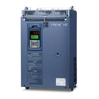
Fuji Electric FRENIC-VG Series User Manual (346 pages)
High Performance, Vector Control Inverter
Brand:
Fuji Electric
| Category:
Inverter
| Size: 23 MB
Table of Contents
Table of Contents
7
Chapter 5 USING STANDARD
19
Standard RS-485 Communications Ports
21
Common Specifications
22
Terminal Specifications for RS-485 Communications
23
Connection Method
24
Communications Support Devices
26
Converters
26
Cables
27
Link Functions
27
Link Command Permission Selection
27
Link Edit Permission Selection
28
S Range Option Priority
28
Referencing and Changing Data
29
Write Restrictions for Function Codes
29
Negative Response and Error Response
30
No Response
30
RS-485 Function Codes
31
Response Interval Time (H39)
31
Disconnection Detection Time (H38)
32
Character Timeouts
32
Timeouts on the Master Side
32
Host Side Procedures
33
Read Procedure
33
Write Procedure
34
Ras
35
Communication Errors
35
Communication Error Measures
38
Fuji General-Purpose Communications
39
Message Format
39
Transmission Frame
39
Standard Frame
40
Option Frame
43
Negative Response Frame
47
Field Descriptions
48
Data Field
48
Sum-Check Field
49
Communication Examples
49
Standard Frame
49
Option Frame
50
ASCII Code Table
51
Program Example
52
Modbus RTU
53
Message Format
53
Transmission Frame
54
Reading Function Codes
55
Writing Single Function Codes
56
Writing Multiple Function Codes
57
Maintenance Code
58
Error Response
59
Error Checking
60
CRC-16 Algorithm
61
CRC-16 Calculation Example
62
Calculating Frame Length
63
Communication Examples
64
Reading
64
FRENIC-VG Loader
65
Specifications
65
Connection
66
USB Connection
66
Communication Via MICREX-SX
67
Function Overview
68
Configuring Function Codes
68
Trace Functions
68
Operation Monitor
70
Common Specifications
77
Specifications Table
77
Inspecting Options after Delivery
80
Inspecting Options
80
Operating Environment
81
Storing Options
82
Temporary Storage
82
Long-Term Storage
82
Installing Internal Options (OPC-VG1- )
83
Removing the Front Cover
83
Installing a Digital 8-Bit Communications Option Card
84
Installing a Digital 8-Bit Option Card
86
Installing a Digital 16-Bit Option Card
88
Installing an Analog Option Card
88
Installing a Field Bus Interface Card
91
Installing a Functional Safety Card
92
Installing a Control Circuit Terminal Option
93
PG Interface Expansion Card OPC-VG1-PG
94
Product Overview
94
Model and Specifications
95
Model
95
Specifications
96
External Dimension Diagram
102
Basic Connection Diagram
103
Terminal Connections
103
Wiring
104
Speed Control
105
Line Speed Control
106
Pulse Train Operation and Synchronized Operation
106
Orientation
108
Synchronized Operation
109
Synchronized Operation System Architecture
109
Synchronized Operation Method
111
Function Codes
113
Check Functions
118
Optional Equipment Check
118
I/O Check
118
Protective Functionality
118
Synchronous Motor Drive PG Interface Card OPC-VG1-Pmpg/Pmpgo
119
Product Overview
119
Model and Specifications
120
Model
120
Specifications
121
Using the Card in Combination with a Fuji Motor
122
External Dimension Diagram
123
Basic Connection Diagram
124
Line Driver Type
125
Open Collector Output Type
126
Connection Diagram for Fuji Servos
127
Function Codes
128
Synchronous Motor Drive PG Interface Card Function Codes
128
Motor Parameters
128
Check Functions
129
Optional Equipment Check
129
Protective Functionality
129
T-Link Interface Card OPC-VG1-TL
130
Product Overview
130
Model and Specifications
131
Inverter Type
131
Specifications
131
External Dimensions
133
Terminal Function
133
Basic Connection Diagram
134
Function Code
136
Protective Operation
138
Light and Heavy Alarms
138
Protective Operation Function Code
139
Data Allocation Addresses
141
Transmission Format
141
Occupied Area
141
Allocated Address
141
Transmission Format
143
Data Format (FRENIC-VG ⇒ MICREX)
143
Data Format (MICREX ⇒ FRENIC-VG)
144
Link Function
146
Link Command Permission Selection
146
Link Edit Permission Selection
147
Data Transmission Example
147
SX Bus Interface Card OPC-VG1-SX
150
Product Overview
150
Model and Specifications
150
Inverter Type
150
Specifications
151
External Dimensions
153
Basic Connection Diagram
154
Function Code
157
Function Code
159
Protective Operation
163
Light and Heavy Alarms
163
Protective Operation Function Code
165
Data Allocation Addresses
167
Transmission Format
167
Area Occupied and Data Allocation Addresses
167
Data Format (FRENIC-VG ⇒ MICREX-SX)
173
Transmission Format
173
Data Format (MICREX-SX ⇒ FRENIC-VG)
178
Link Function
186
Data Transmission Example
186
System Configuration Definition
188
Programming Support Tool Expert (D300Win)
188
Application Program Examples
192
Multiple Option Application Examples
194
Installed with T-Link Interface Card
194
Installed with High-Speed Serial Communication-Capable Terminal Block
195
High-Speed Serial Communication-Capable Terminal Block OPC-VG1-TBSI
196
Product Overview
196
Multiplex System
196
Model and Specifications
197
Model
197
Specifications
197
External Dimensions
201
Connecting Optical Fiber Cable
202
Basic Connection Diagrams
204
Connection Diagram of Multiwinding Motor Control System
204
Connection Diagram of Direct Parallel Connection Control System
206
Configuration of Function Codes
210
Operation Procedure
212
Preparation
212
Operation Method
213
Protective Functions
214
Process in Protective Operation
214
Processing for Light Alarms
215
Inter-Inverter Link Error ( Erb )
215
Operation Procedure Error ( Er6 )
215
I/O Interface
216
Switching between Multiwinding and Single-Winding Motor Drive (Multiwinding System)
222
Running with Reduced Number of Units
223
Wiring Inductance (Direct Parallel Connection)
227
Wiring Length in MD Specification
228
Wiring Length in LD Specification
228
CC-Link Interface Card OPC-VG1-CCL
229
Product Overview
229
Model and Specifications
230
Model
230
Specifications
230
External Dimension Drawing
234
Basic Connection Diagram
235
Function Code
236
Standard Function Code
236
Communication Dedicated Function Codes
236
Option Dedicated Function Codes
237
Protection Operation
238
Light Alarm and Heavy Alarm
238
Protection Operation Function Codes
240
Applicable Format List
243
VG7 Compatible Mode with 1 Station Occupied
244
Remote I/O Signal in the VG7 Compatible Mode
244
Remote Register in VG7 Compatible Mode (O32=0)
246
Monitor Code/Command Code (O32=0) in VG7 Compatible Mode
247
Mode with 1 Station Occupied
249
Remote I/O Signal in 1 X Mode (O32=1)
249
Remote Register Signal in 1 X Mode (O32 = 1)
251
Monitor Code/Command Code (O32 = 1 to 4)
252
Mode with 1 Station Occupied
255
Remote I/O Signal in 2 X Mode (O32=2)
255
Remote Register Signal in 2 X Mode (O32=2)
255
Mode with 1 Station Occupied
256
Remote I/O Signal in 4 X Mode (O32=3)
256
Remote Register Signal in 4 X Mode (O32=3)
256
Mode with 1 Station Occupied (O32=4)
258
Remote I/O Signal in 8 X Mode (O32=4)
258
Remote Register Signal in 8 X Mode (O32=4)
258
Link Function
261
Link Command Permission Selection
261
Link Edition Permission Selection
262
Setting-Up Procedure
263
Application Program Examples
263
System Configuration
263
Master Unit Outline
263
17-Bit High Resolution ABS Interface Card OPC-VG1-SPGT
264
Product Overview
264
Model and Specifications
264
Model
264
Specifications
265
External Dimension Drawing
267
Connection
268
Connector and Terminal Specifications
268
Basic Connection Diagram
269
Function Code
271
Function Codes Related to Motor Control
271
Protective Functions
274
Alarm Display List
274
Actions to be Taken for Alarms
274
Check Function
274
Option Mounting Check
274
Related Option
275
F/V Converter OPC/MCA-VG1-FV (Available Soon)
279
Product Overview
279
Model and Specifications
279
Model
279
Specifications
280
External Dimensions
281
Internal Block Diagram
282
Adjustment Method
283
Basic Connection Diagram
285
6.10 Synchro Interface OPC/MCA-VG1-SN
287
Product Overview
287
Model and Specifications
287
Model
287
Specifications
288
External Dimension Diagram
289
Internal Block Diagram
289
Adjustment Method
290
Description of Adjustment Locations
290
Installing and Adjusting the Synchro Interface
291
6.11 DI Interface Card OPC-VG1-DI
292
Product Overview
292
Model and Specifications
293
Model
293
Specifications
294
External Dimension Drawing
296
Basic Connection Diagram
297
Function Codes
298
Data Latch Function
298
Selecting Binary or BCD Input
299
Controlled Variable Input
300
Check Functions
301
Option Installation Check
301
I/O Check
301
6.12 DIO Expansion Card OPC-VG1-DIO
302
Product Overview
302
Models and Specifications
303
Models
303
Specifications
304
Dimensions
307
Basic Schematic Diagrams
308
Basic Schematic Diagram (DIOA)
308
Basic Schematic Diagram (DIOB)
309
Function Codes
310
DIOA Selected
310
DIOB Selected
311
Check Function
312
Mounting Check on Optional Cards
312
I/O Check
312
6.13 AIO Expansion Card OPC-VG1-AIO
313
Product Overview
313
Models and Specifications
314
Models
314
Specifications
315
Function Codes
318
Check Function
319
Optional PG Changeover Card MCA-VG1-CPG (Available Soon)
320
Product Overview
320
Model and Specifications
320
Model
320
Specifications
320
Dimensions
321
Installation Method
321
Basic Schematic Diagram
322
Operation Method
324
6.15 E-SX Bus Interface Card OPC-VG1-ESX
325
Product Overview
325
Model and Specifications
325
Model
325
Specifications
326
External Dimension Drawings
328
Basic Connections
329
Related Function Codes
331
Protective Operations
332
Light Alarms and Heavy Alarms in E-SX Bus Communication ( Er4 )
332
E-SX Related Alarms ( Are , Arf )
335
Other Inverter Alarms
335
Data Addresses (IQ Area)
336
Supported Formats
336
Input/Output Data Address Assignments
336
Format Details
337
I Area (MICREX-SX ← FRENIC-VG)
337
Q Area (MICREX-SX → FRENIC-VG)
339
Data Transmission Examples
340
Synchronization of E-SX Bus Tact Cycle and Inverter Control Cycle
342
Conditions Required for Tact Synchronization
342
Checking the Tact Synchronization Status
342
Action When Synchronization Is Lost ( Are )
342
6.15.11 Support Tool Interface
343
6.15.11.1 Configuration Definition Method
343
6.15.11.2 Compatible Versions of the SPH3000MM and Support Tool
343
Advertisement
Related Products
Fuji Electric frenic mini series
Fuji Electric FRENIC-Ace series
Fuji Electric FRENIC5000G11S Series
Fuji Electric FRENIC5000P11S Series
Fuji Electric FRENIC-HVAC series
Fuji Electric Frenic Eco Series
Fuji Electric FRENIC5000 P5 Series
Fuji Electric FRENIC5000 P7 Series
Fuji Electric FRENIC5000 G9S Series
Fuji Electric FRENIC5000 P9S Series
Fuji Electric Categories
Air Conditioner
Inverter
Measuring Instruments
Controller
Control Unit
More Fuji Electric Manuals
Login
Sign In
OR
Sign in with Facebook
Sign in with Google
Upload manual
Upload from disk
Upload from URL