Sign In
Upload
Manuals
Brands
Fuji Electric Manuals
Inverter
Frenic Mega Series
Fuji Electric Frenic Mega Series Manuals
Manuals and User Guides for Fuji Electric Frenic Mega Series. We have
5
Fuji Electric Frenic Mega Series manuals available for free PDF download: User Manual, Connection Manual
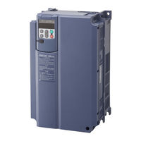
Fuji Electric Frenic Mega Series User Manual (774 pages)
High Performance, Multifunction Inverter
Brand:
Fuji Electric
| Category:
Inverter
| Size: 31 MB
Table of Contents
Table of Contents
12
General Precautions
5
Safety Precautions
5
Protective Functions
7
Chapter 1 Before Use
20
Features
22
Control System
36
Motor Drive Controls
37
Acceptance Inspection
38
External View
39
Installation and Wiring
41
Recommended Configuration
42
Precautions for Using Inverters
43
Storage Environment
44
Precautions in Introducing Inverters
45
Operation
46
Function Codes
47
Precautions in Running Inverters
50
Chapter 2 INSTALLATION and WIRING
54
Installation
54
Wiring
56
Running a Fuji Motor Exclusively Designed for Vector Control
58
Removing and Mounting the Front Cover and the Wiring Guide
60
Wiring Precautions
61
Main Circuit Terminals
63
Terminal Layout Diagrams (Main Circuit Terminals)
65
Description of Terminal Functions (Main Circuit Terminals)
68
Control Circuit Terminals (Common to All Inverter Types)
72
Notes on Control Circuit Wiring
73
Terminal Functions (Control Circuit)
74
Switching Connectors
85
Setting up the Slide Switches
88
Attachment and Connection of Keypad
90
Chapter 6 TROUBLESHOOTING
91
Protective Functions
91
Reading Maintenance Information
98
Chapter 3 KEYPAD FUNCTIONS (OPERATING with the KEYPAD)
100
LED Monitor, Keys and LED Indicators on the Keypad
100
Chapter 4 Overview of Operation Modes
103
Running Mode
105
Monitoring Light Alarms
107
Setting up Frequency and PID Commands
108
Running/Stopping the Motor
113
Remote and Local Modes
114
External Run/Frequency Command
115
Programming Mode
116
Chapter 5 Setting up Basic Function Codes Quickly "Quick Setup"
118
Setting up Function Codes Menu #1 "Data Setting"
121
Checking Changed Function Codes Menu #2 "Data Checking"
124
Monitoring the Running Status Menu #3 "Drive Monitoring"
125
Checking I/O Signal Status Menu #4 "I/O Checking"
129
Maintenance Information"
134
Maintenance and Inspection
135
Reading Alarm Information Menu #6 "Alarm Information"
139
Copying Data Menu #7 "Data Copying"
142
Alarm Mode
146
USB Connectivity
148
Chapter 4 Operation
150
Test Run
152
Test Run Procedure
152
Checking Prior to Powering on
153
Powering on and Checking
153
Selecting an Inverter Drive Mode (HD/MD/LD)
154
Selecting a Motor Drive Control
155
Basic Settings of Function Codes < 1
159
Basic Settings/Tuning of Function Codes < 2
160
Basic Settings/Tuning of Function Codes < 3
163
Basic Settings of Function Codes < 4
168
Basic Settings of Function Codes < 5
169
Basic Settings/Tuning of Function Codes < 6
170
Running the Inverter for Motor Operation Check
173
Preparation for Production Run
175
Special Operation
176
Jogging Operation
176
Remote and Local Modes
177
External Run/Frequency Command
178
Chapter 5 Function Codes
180
Overview of Function Codes
182
Function Code Tables
183
Code Index by Purpose
218
Configuring the Minimal Requirements for the Inverter to Just Run the Motor
218
Setting up the Frequency
218
Frequency Setting from the Keypad
218
Frequency Setting by Analog Input
218
Other Frequency Settings
219
Entering a Run Command
220
Starting/Stopping the Motor
221
Specifying the Acceleration/Deceleration (Time, Mode, and Pattern)
221
Adjusting the Running Performance
222
Controlling the Motor
223
Motor Drive Control to be Selected
223
Motor Parameters to be Set up
224
Setting up I/O Terminals
225
Outputting Monitored Data
225
Keeping on Running the Motor
226
Detecting and Outputting Status Signals
227
Running in Various Operation Modes
228
Setting up Controls Suited for Individual Applications
230
Droop Control
230
PID Process Control
231
PID Dancer Control
233
Customizing the Keypad
235
Controlling the Inverter Via Communications Line
235
Using the Customizable Logic
236
Activating the Protective Functions
237
Protection of Machinery with Limiters
237
Protection of Motors
237
Using Other Protective and Safety Functions
238
Maintenance
240
Maintenance of Inverters
240
Maintenance of Machinery
241
Details of Function Codes
242
F Codes (Fundamental Functions)
242
E Codes (Terminal Functions)
303
Lu Undervoltage
320
S Overspeed
332
C Codes (Control Functions)
347
P Codes (Motor 1 Parameters)
356
H Codes (High Performance Functions)
362
Er4 Option Communications Error
384
Cof PID Feedback Wire Break
385
A Code (Motor 2 Parameter) B Code (Motor 3 Parameter) R Code (Motor 4 Parameter)
392
J Codes (Application Functions 1)
395
D Codes (Application Functions 2)
416
U Codes (Application Functions 3)
430
Y Codes (Link Functions)
453
Chapter 7 Maintenance and Inspection
458
Daily Inspection
460
Periodic Inspection
461
List of Periodic Replacement Parts
463
Judgment on Service Life
463
Measurement of Electrical Amounts in Main Circuit
467
Insulation Test
468
Inquiries about Product and Guarantee
469
Chapter 8 Block Diagrams for Control Logic
472
Symbols Used in Block Diagrams and Their Meanings
474
Drive Frequency Command Block
475
Drive Command Block
477
Control Block
479
V/F Control
479
V/F Control with Speed Sensor
481
Vector Control With/Without Speed Sensor
483
PID Process Control Block
485
PID Dancer Control Block
487
FMA/FMP Output Selector
489
Chapter 9 Running through Rs-485 Communication
490
Running through Rs-485 Communication
490
Overview on RS-485 Communication
492
Common Specifications
493
Chapter 8 BLOCK DIAGRAMS for CONTROL LOGIC
493
RS-485 Common Specifications
493
Terminal Specifications for RS-485 Communications
494
Communications Port 1 (for Connecting the Keypad)
494
Communications Port 2 (Control Circuit Terminals)
494
Connection Method
495
Communications Support Devices
497
Communications Level Converters
497
Requirements for the Cable (COM Port 1: for RJ-45 Connector)
498
Requirements for the Cable (COM Port 2: for RS-485 Connector)
498
Branch Adapter for Multi-Drop
498
Noise Suppression
498
Overview of FRENIC Loader
499
Specifications
499
Connection
500
Function Overview
500
Setting of Function Code
500
Multi-Monitor
501
Running Status Monitor
502
Test-Running
503
Real-Time Trace
504
Historical Trace
505
USB Port on the Standard Keypad
506
Chapter 10 Selecting Optimal Motor and Inverter Capacities
508
Selecting Motors and Inverters
510
Output Torque Characteristics
510
Selection Procedure
513
Equations for Selections
516
Load Torque During Constant Speed Running
516
Acceleration and Deceleration Time Calculation
518
Heat Energy Calculation of Braking Resistor
523
Calculating the RMS Rating of the Motor
524
Selecting a Braking Resistor
525
Selection Procedure
525
Notes on Selection
525
Selecting an Inverter Drive Mode (HD/MD/LD)
526
Precaution in Making the Selection
526
Guideline for Selecting Inverter Drive Mode and Capacity
527
Selecting a Motor Drive Control
528
Features of Motor Drive Controls
528
Selecting a Motor Drive Control by Purpose
533
Chapter 11 Selecting Peripheral Equipment
534
Configuring the FRENIC-MEGA
536
Selecting Wires and Crimp Terminals
537
Recommended Wires
541
Peripheral Equipment
549
Function Overview
549
Connection Example and Criteria for Selection of Circuit Breakers
551
Surge Killer for L-Load
556
Arrester
557
Surge Absorber
558
Filter Capacitor for Radio Noise Reduction
559
Peripheral Equipment Options
560
Braking Resistors (Dbrs) and Braking Units
560
Option
560
Power Regenerative PWM Converters, RHC Series
567
Terminal Functions
569
Communications Specifications
569
DC Reactor (DCR)
582
AC Reactor (ACR)
588
Surge Suppression Unit (SSU)
593
Output Circuit Filter (OFL)
594
Zero-Phase Reactors for Reducing Radio Noise (ACL)
597
IP40 Kits (P40G1- )
598
Options for Operation and Communication
600
External Frequency Command Potentiometer (External Volume)
600
Multi-Function Keypad (TP-G1-J1, TP-G1-C1)
602
Extension Cable for Remote Operation
603
Inverter Support Loader
603
PG Interface Card (OPC-G1-PG)
604
PG Interface (5 V Line Driver) Card (OPC-G1
607
PG Interface (5 V Line Driver X 2) Card (OPC-G1
611
Relay Output Interface Card (OPC-G1-RY)
614
Digital Input Interface Card (OPC-G1-DI)
616
Digital Output Interface Card (OPC-G1-DO)
619
Analog Interface Card (OPC-G1-AIO)
621
T-Link Communications Card (OPC-G1-TL)
626
SX-Bus Communications Card (OPC-G1-SX)
630
CC-Link Communications Card (OPC-G1-CCL)
633
PROFIBUS-DP Communications Card (OPC-G1-PDP)
635
Devicenet Communications Card (OPC-G1-DEV)
639
Canopen Communications Card (OPC-G1-COP)
642
Option Cards for Operation and Communication
645
About Option Cards for Operation and Communication
645
Meter Options
646
Frequency Meters
646
Chapter 12 Specifications
647
Standard Model 1 (Basic Type)
649
Three-Phase 200 V Class Series
649
Three-Phase 400 V Class Series
650
Standard Model 2 (EMC Filter Built-In Type)
653
Three-Phase 200 V Class Series
653
Three-Phase 400 V Class Series
654
Standard Model 3 (DC Reactor Built-In Type)
657
Three-Phase 200 V Class Series
657
Three-Phase 400 V Class Series
658
Common Specifications
659
External Dimensions
666
Basic Type and EMC Filter Built-In Type
666
DC Reactor Built-In Type
675
Keypad
676
Chapter 13 Compliance with Standards
677
Compliance with UL Standards and Canadian Standards (Cul Certification)
679
Conformity with UL Standards and Canadian Standards (Cul Certification)
679
General
679
Conformity with EMC Directives in Europe
684
General
684
Recommended Installation Method
685
Leakage Current from the EMC Filter Built-In Type
687
Conformity with European Standards
684
Regulations on Harmonics in Europe
688
General
688
Compliance
688
Conformity with Low Voltage Directive in Europe
689
General
689
Note
689
Radio Waves Act (South Korea)
694
Appendices
695
App. a Advantageous Use of Inverters (Notes on Electrical Noise)
697
Effect of Inverters on Other Devices
697
Noise
698
Noise Prevention
700
Voltage (General-Purpose Inverter)
708
Application to General-Purpose Inverters
708
Compliance to the Harmonic Suppression for Customers Receiving High Voltage or Special High Voltage
709
App. C Effect on Insulation of General-Purpose Motors Driven with 400 V Class Inverters
713
Generating Mechanism of Surge Voltages
713
Effect of Surge Voltages
714
Countermeasures against Surge Voltages
714
Regarding Existing Equipment
715
App. D Inverter Generating Loss
716
App. E Conversion from si Units
717
App. F Allowable Current of Insulated Wires
719
App. G Replacement Information
721
External Dimensions Comparison Tables
721
Terminal Arrangements and Symbols
725
Function Code
732
G.3 Function Code
732
Series)
733
Advertisement
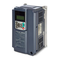
Fuji Electric Frenic Mega Series User Manual (680 pages)
High Performance, Multifunction Inverter
Brand:
Fuji Electric
| Category:
Inverter
| Size: 22 MB
Table of Contents
Table of Contents
9
Safety Precautions
5
Features
15
Control System
29
Motor Drive Controls
31
External View and Terminal Blocks
32
Recommended Configuration
34
Chapter 2 Specifications
35
Standard Model 2 (Inverter with Built-In DC Reactor)
44
Three-Phase 230 V Series
44
Three-Phase 460 V Series
46
Common Specifications
48
Terminal Specifications
56
Terminal Functions
56
Setting up the Slide Switches
65
Terminal Arrangement and Screw Specifications
67
Main Circuit Terminals
67
Control Circuit Terminals (Common to All Inverter Types)
70
Wiring Precautions
70
Operating Environment and Storage Environment
73
Operating Environment
73
Storage Environment
74
Temporary Storage
74
Long-Term Storage
74
Precautions for Using Inverters
75
Precautions in Introducing Inverters
75
Wiring Precautions
76
Precautions in Running Inverters
80
Precautions in Using Special Motors
80
External Dimensions
82
Standard Inverter
82
Inverter with Built-In DC Reactor
91
Keypad (TP-G1W-J1)
94
Connection Diagrams
95
Running a Standard Motor
95
Running a Fuji Motor Exclusively Designed for Vector Control
97
Protective Functions
99
Chapter 3 Selecting Optimal Motor and Inverter Capacities
105
Selecting Motors and Inverters
107
Motor Output Torque Characteristics
107
Selection Procedure
110
Equations for Selections
113
Load Torque During Constant Speed Running
113
1 ] General Equation
113
2 ] Obtaining the Required Force F
114
Acceleration and Deceleration Time Calculation
116
1 ] Calculation of Moment of Inertia
116
2 ] Calculation of the Acceleration Time
118
3 ] Calculation of the Deceleration Time
119
4 ] Calculating Non-Linear Acceleration/Deceleration Time
119
Heat Energy Calculation of Braking Resistor
121
1 ] Calculation of Regenerative Energy
121
Calculating the RMS Rating of the Motor
122
Selecting a Braking Resistor
123
Selection Procedure
123
Notes on Selection
123
Selecting an Inverter Drive Mode (LD/MD/HD)
124
Precaution in Making the Selection
124
Guideline for Selecting Inverter Drive Mode and Capacity
125
Selecting a Motor Drive Control
126
Features of Motor Drive Controls
126
Selecting a Motor Drive Control by Purpose
131
Chapter 4 Selecting Peripheral Equipment
133
Selecting Peripheral Equipment
133
Configuring the FRENIC-MEGA
135
Selecting Wires and Crimp Terminals
136
Recommended Wires
140
Peripheral Equipment
142
Molded Case Circuit Breaker (MCCB), Residual-Current-Operated Protective Device (RCD)/ Earth Leakage Circuit Breaker (ELCB) and Magnetic Contactor (MC)
142
1 ] Functional Overview
142
2 ] Connection Example and Criteria for Selection of Circuit Breakers
144
Surge Killers for L-Load
149
Arresters
150
Surge Absorbers
151
Filtering Capacitors Suppressing am Radio Band Noises
152
Chapter 1 INTRODUCTION to FRENIC-MEGA
153
Chapter 2 SPECIFICATIONS
153
Standard Models
153
2 ] Braking Units
154
3 ] Specifications
155
4 ] External Dimensions
157
Power Regenerative PWM Converters, RHC Series
159
1 ] Overview
159
2 ] Specifications
160
Keypad
161
3 ] Function Specifications
162
4 ] Converter Configuration
167
5 ] External Dimensions
172
DC Reactors (Dcrs)
177
AC Reactors (Acrs)
180
Zero-Phase Reactors for Reducing Radio Noise (Acls)
181
Enclosed - Type 1 Kit
182
1 ] Overview
182
2 ] Configuration
182
3 ] Specifications
183
4 ] Change Settings
184
Options for Operation and Communication
185
External Frequency Command Potentiometer
185
Extension Cable for Remote Operation
187
Inverter Support Loader Software
188
PG Interface Card (OPC-G1-PG)
189
PG Interface (5 V Line Driver) Card (OPC-G1
192
PG Interface (5 V Line Driver X 2) Card (OPC-G1
196
Relay Output Interface Card (OPC-G1-RY)
199
Digital Input Interface Card (OPC-G1-DI)
201
Digital Output Interface Card (OPC-G1-DO)
204
Analog Interface Card (OPC-G1-AIO)
206
T-Link Communications Card (OPC-G1-TL)
211
SX-Bus Communications Card (OPC-G1-SX)
214
CC-Link Communications Card (OPC-G1-CCL)
217
PROFIBUS-DP Communications Card (OPC-G1-PDP)
219
Devicenet Communications Card (OPC-G1-DEV)
222
Canopen Communications Card (OPC-G1-COP)
225
List of Option Cards and Connection Ports
228
Meter Options
229
Frequency Meters
229
Selecting Options
153
Peripheral Equipment Options
153
Braking Resistors (Dbrs) and Braking Units
153
1 ] Braking Resistors (Dbrs)
153
Chapter 5 Function Codes
231
Function Codes
231
Overview of Function Codes
233
Function Code Tables
234
Function Code Index by Purpose
268
Configuring the Minimal Requirements for the Inverter to Just Run the Motor
268
Setting up the Frequency
268
Frequency Setting from the Keypad
268
Frequency Setting by Analog Input
269
Other Frequency Settings
269
Entering a Run Command
270
Starting/Stopping the Motor
271
Specifying the Acceleration/Deceleration (Time, Mode, and Pattern)
271
Adjusting the Running Performance
272
Controlling the Motor
273
Motor Drive Control to be Selected
273
Motor Parameters to be Set up
274
Setting up I/O Terminals
275
Outputting Monitored Data
275
Keeping on Running the Motor
276
Outputting Status Signals
277
Running in Various Operation Modes
278
Setting up Controls Suited for Individual Applications
280
Droop Control
280
PID Process Control
280
PID Dancer Control
282
Customizing the Keypad
284
Controlling the Inverter Via Communications Line
285
Using the Customizable Logic
286
Activating the Protective Functions
286
Protection of Machinery with Limiters
286
Protection of Motors
287
Using Other Protective and Safety Functions
288
Maintenance
290
Maintenance of Inverters
290
Maintenance of Machinery
290
Details of Function Codes
291
F Codes (Fundamental Functions)
291
E Codes (Extension Terminal Functions)
348
C Codes (Control Functions)
390
P Codes (Motor 1 Parameters)
395
H Codes (High Performance Functions)
401
A Codes (Motor 2 Parameters) B Codes (Motor 3 Parameters) R Codes (Motor 4 Parameters)
433
J Codes (Application Functions 1)
437
D Codes (Application Functions 2)
459
U Codes (Application Functions 3)
469
Y Codes (Link Functions)
491
Chapter 6 Block Diagrams for Control Logic
497
Block Diagrams for Control Logic
497
Symbols Used in Block Diagrams and Their Meanings
499
Drive Frequency Command Block
500
Drive Command Block
502
Control Block
504
V/F Control
504
V/F Control with Speed Sensor
506
Vector Control With/Without Speed Sensor
508
PID Process Control Block
510
PID Dancer Control Block
512
FM1/FM2 Output Selector
514
Chapter 7 Keypad Functions
515
Keypad Functions (Operating with the Keypad
515
LED Monitor, LCD Monitor, and Keys
517
Overview of Operation Modes
520
Running Mode
521
Monitoring the Running Status on the LED Monitor
521
Monitoring Light Alarms
523
Troubleshooting
523
Configuring Frequency and PID Commands
525
Running or Stopping the Motor
530
Jogging (Inching) the Motor
532
Switching between Remote and Local Modes
533
External Run/Frequency Command
534
Programming Mode
535
Setting up Function Codes Quickly Using Quick Setup -- Menu #0 "Quick Setup
536
Setting up Function Codes -- Menu #1 "Data Setting
537
Checking Changed Function Codes -- Menu #2 "Data Checking
540
Monitoring the Running Status -- Menu #3 "Drive Monitoring
541
Checking I/O Signal Status -- Menu #4 "I/O Checking
544
Reading Maintenance Information -- Menu #5 "Maintenance Information
548
Reading Alarm Information -- Menu #6 "Alarm Information
554
Viewing Causes of Alarm -- Menu #7 "Alarm Cause
559
Data Copying -- Menu #8 "Data Copying
561
Measuring Load Factor -- Menu #9 "Load Factor Measurement
568
Changing Function Codes Covered by Quick Setup -- Menu #10 "User Setting" --
572
Helping Debugging for Communication -- Menu #11 "Communication Debugging
573
Alarm Mode
574
Chapter 8 Running through Rs-485 Communication
577
Overview on RS-485 Communication
579
Common Specifications
580
Terminal Specifications for RS-485 Communications
581
Connection Method
582
Communications Support Devices
584
Noise Suppression
586
Overview of FRENIC Loader
587
Specifications
587
Connection
588
Function Overview
589
Setting of Function Code
589
Multi-Monitor
590
Running Status Monitor
591
Test-Running
592
Real-Time Trace
593
Historical Trace
594
USB Port on the Optional Remote Keypad
595
Chapter 9 Troubleshooting
597
Protective Functions
599
Before Proceeding with Troubleshooting
602
If Neither an Alarm Code nor "Light Alarm" Indication (L-AL) Appears on the LED Monitor
603
If Neither an Alarm Code nor "Light Alarm" Indication ( L-Al ) Appears on the LED Monitor
603
Abnormal Motor Operation
603
Problems with Inverter Settings
610
If an Alarm Code Appears on the LED Monitor
611
If the "Light Alarm" Indication (L-AL) Appears on the LED Monitor
626
If the "Light Alarm" Indication ( L-Al ) Appears on the LED Monitor
626
If an Abnormal Pattern Appears on the LED Monitor Except Alarm Codes and "Light Alarm" Indication (L-AL)
627
If an Abnormal Pattern Appears on the LED Monitor Except Alarm Codes and "Light Alarm
627
If the Inverter Is Running on Single-Phase Power
629
Appendices
631
App. a Advantageous Use of Inverters (Notes on Electrical Noise
633
Effect of Inverters on Other Devices
633
A.2 Noise
634
Noise Prevention
636
Special High Voltage
644
Application to General-Purpose Inverters
644
App. B Japanese Guideline for Suppressing Harmonics by Customers Receiving High Voltage or Special High Voltage
644
Compliance to the Harmonic Suppression for Customers Receiving High Voltage or Special High Voltage
645
App. C Effect on Insulation of General-Purpose Motors Driven with 400 V Class Inverters
650
Generating Mechanism of Surge Voltages
650
Effect of Surge Voltages
651
Countermeasures against Surge Voltages
651
Regarding Existing Equipment
652
App. D Inverter Generating Loss
653
App. E Conversion from si Units
654
Index
669
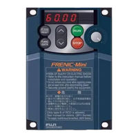
Fuji Electric Frenic Mega Series User Manual (634 pages)
High Performance, Multifunction Inverter
Brand:
Fuji Electric
| Category:
Inverter
| Size: 12 MB
Table of Contents
Table of Contents
8
Safety Precautions
5
Introduction to Frenic-Mega
14
Features
16
Chapter 1 INTRODUCTION to FRENIC-MEGA
27
Control System
27
Motor Drive Controls
28
External View and Terminal Blocks
29
Recommended Configuration
31
Specifications
32
Chapter 2 SPECIFICATIONS
34
Standard Model 1 (Basic Type)
34
Standard Model 2 (EMC Filter Built-In Type)
36
Common Specifications
38
Terminal Specifications
45
Setting up the Slide Switches
55
Terminal Arrangement Diagram and Screw Specifications
57
Control Circuit Terminals (Common to All Inverter Types)
60
Operating Environment and Storage Environment
61
Storage Environment
62
Precautions for Using Inverters
63
Wiring Precautions
64
Precautions in Running Inverters
68
External Dimensions
70
Keypad
76
Connection Diagrams
77
Running a Fuji Motor Exclusively Designed for Vector Control
79
Protective Functions
81
Chapter 3 SELECTING OPTIMAL MOTOR and INVERTER CAPACITIES
88
Selecting Motors and Inverters
88
Selection Procedure
91
Equations for Selections
94
Acceleration and Deceleration Time Calculation
96
Heat Energy Calculation of Braking Resistor
101
Calculating the RMS Rating of the Motor
102
Selecting a Braking Resistor
103
Selecting an Inverter Drive Mode
104
Guideline for Selecting Inverter Drive Mode and Capacity
105
Selecting a Motor Drive Control
106
Selecting a Motor Drive Control by Purpose
111
Selecting Peripheral Equipment
112
Chapter 4 SELECTING PERIPHERAL EQUIPMENT
114
Configuring the FRENIC-MEGA
114
Selecting Wires and Crimp Terminals
115
Recommended Wires
119
Peripheral Equipment
127
Surge Killers for L-Load
132
Arresters
133
Surge Absorbers
134
Filtering Capacitors Suppressing am Radio Band Noises
135
Power Regenerative PWM Converter, RHC Series
143
Selecting Options
152
DC Reactors (Dcrs)
157
AC Reactors (Acrs)
162
Surge Suppression Unit (SSU)
167
Output Circuit Filters (Ofls)
168
Zero-Phase Reactor for Reducing Radio Noise (ACL)
171
Options for Operation and Communication
174
Multi-Function Keypad (TP-G1-J1, TP-G1-C1)
175
Extension Cable for Remote Operation
176
Inverter Support Loader Software
177
PG Interface Card (OPC-G1-PG)
178
PG Interface (5 V Line Driver) Card (OPC-G1-PG2)
181
Relay Output Interface Card (OPC-G1-RY)
185
Digital Input Interface Card (OPC-G1-DI)
187
Digital Output Interface Card (OPC-G1-DO)
190
Analog Interface Card (OPC-G1-AIO)
192
T-Link Communications Card (OPC-G1-TL)
197
SX-Bus Communications Card (OPC-G1-SX)
200
CC-Link Communications Card (OPC-G1-CCL)
203
PROFIBUS-DP Communications Card (OPC-G1-PDP)
205
Devicenet Communications Card (OPC-G1-DEV)
208
Canopen Communications Card (OPC-G1-COP)
211
Option Cards for Operation and Communication
213
Meter Options
214
Chapter 5 FUNCTION CODES
218
Overview of Function Codes
218
Function Code Tables
219
Function Code Index by Purpose
248
Frequency Setting by Analog Input
249
Entering a Run Command
250
Starting/Stopping the Motor
251
Adjusting the Running Performance
252
Controlling the Motor
253
Motor Parameters to be Set up
254
Setting up I/O Terminals
255
Keeping on Running the Motor
256
Outputting Status Signals
257
Running in Various Operation Modes
258
Setting up Controls Suited for Individual Applications
259
PID Dancer Control
261
Customizing the Keypad
263
Controlling the Inverter Via Communications Line
264
Activating the Protective Functions
265
Using Other Protective and Safety Functions
266
Maintenance
268
Details of Function Codes
269
E Codes (Extension Terminal Functions)
319
C Codes (Control Functions)
356
P Codes (Motor Parameters)
361
H Codes (High Performance Functions)
366
A Codes (Motor 2 Parameters) B Codes (Motor 3 Parameters) R Codes (Motor 4 Parameters)
394
J Codes (Application Functions 1)
397
D Codes (Application Functions 2)
416
Y Codes (Link Functions)
422
Block Diagrams for Control Logic
428
Chapter 6 BLOCK DIAGRAMS for CONTROL LOGIC
430
Symbols Used in Block Diagrams and Their Meanings
430
Drive Frequency Command Block
431
Drive Command Block
433
Control Block
435
Vector Control With/Without Speed Sensor
437
PID Process Control Block
439
PID Dancer Control Block
441
FMA/FMP Output Selector
443
Keypad Functions (Operating with the Keypad
444
Chapter 7 KEYPAD FUNCTIONS (OPERATING with the KEYPAD)
446
LED Monitor, Keys and LED Indicators on the Keypad
446
Overview of Operation Modes
449
Running Mode
451
Monitoring Light Alarms
453
Setting up Frequency and PID Commands
454
Running/Stopping the Motor
459
Remote and Local Modes
460
External Run/Frequency Command
461
Programming Mode
462
Setting up Basic Function Codes Quickly -- Menu #0 "Quick Setup" --
464
Setting up Function Codes -- Menu #1 "Data Setting" --
467
Checking Changed Function Codes -- Menu #2 "Data Checking" --
470
Monitoring the Running Status -- Menu #3 "Drive Monitoring" --
471
Checking I/O Signal Status -- Menu #4 "I/O Checking" --
475
Reading Maintenance Information -- Menu #5 "Maintenance Information" --
480
Reading Alarm Information -- Menu #6 "Alarm Information" --
485
Copying Data -- Menu #7 "Data Copying" --
488
Alarm Mode
491
USB Connectivity
493
Chapter 8 Running through Rs-485 Communication
494
Overview on RS-485 Communication
496
Common Specifications
497
RS-485 Common Specifications
497
Terminal Specifications for RS-485 Communications
498
Connection Method
499
Communications Support Devices
501
Noise Suppression
502
Overview of FRENIC Loader
503
Specifications
503
Connection
504
Function Overview
504
Setting of Function Code
504
Multi-Monitor
505
Running Status Monitor
506
Test-Running
507
Real-Time Trace
508
Historical Trace
509
USB Port on the Standard Keypad
510
Chapter 9 Troubleshooting
512
Troubleshooting
512
Protective Functions
514
Before Proceeding with Troubleshooting
516
If Neither an Alarm Code nor "Light Alarm" Indication
517
Abnormal Motor Operation
517
Momentary Power Failure
522
Problems with Inverter Settings
523
If an Alarm Code Appears on the LED Monitor
524
If an Abnormal Pattern Appears on the LED Monitor While Neither an Alarm Code nor
539
Is Displayed
539
Appears on the LED Monitor
539
Appendices
540
App. a Advantageous Use of Inverters (Notes on Electrical Noise
542
Effect of Inverters on Other Devices
542
Noise
542
Chapter 9 TROUBLESHOOTING
543
A.2 Noise
543
Noise Prevention
545
A.3 Noise Prevention
545
App. B Japanese Guideline for Suppressing Harmonics by Customers Receiving High Voltage or Special High Voltage
553
Application to General-Purpose Inverters
553
Compliance to the Harmonic Suppression for Customers Receiving High Voltage or Special High Voltage
554
App. C Effect on Insulation of General-Purpose Motors Driven with 400 V Class Inverters
558
Generating Mechanism of Surge Voltages
558
Countermeasures against Surge Voltages
559
Effect of Surge Voltages
559
Regarding Existing Equipment
560
App. D Inverter Generating Loss
561
App. E Conversion from si Units
562
App. F Allowable Current of Insulated Wires
564
App. G Replacement Information
566
External Dimensions Comparison Tables
566
Terminal Arrangements and Symbols
569
1 ] FRENIC5000G9S Vs. FRENIC-MEGA
576
2 ] FRENIC5000P9S Vs. FRENIC-MEGA
576
3 ] FRENIC5000G11S Vs. FRENIC-MEGA
576
4 ] FRENIC5000P11S Vs. FRENIC-MEGA
576
Function Codes
576
G.3 Function Codes
576
Advertisement
Fuji Electric Frenic Mega Series User Manual (172 pages)
RS-485
Brand:
Fuji Electric
| Category:
Inverter
| Size: 1 MB
Table of Contents
Safety Precautions
6
Table of Contents
7
Chapter 1 Overview1
12
Features
12
List of Functions
13
Chapter 2 Common Specifications1
16
Specifications of RS-485 Communications
16
Specification of the RJ-45 Connector for RS-485 Communications (Modular Jack)
18
Specification of the Terminal for RS-485 Communications
19
Connector (Modular Jack) for Function Expansion
20
Specification of Connection Cable for RS-485 Terminal
22
Connections
23
Basic Connection
23
Connection Procedures
26
Devices for Connection
30
Measures against Noise
31
Switching to Communications
33
Functions for the Switching
33
Link Functions (Operation Selection)
34
How to Switch Communications Enabled/Disabled
35
Link Functions for Supporting Data Input (Operation Select)
36
Making RS-485-Related Settings
37
Link Function (RS-485 Setting)
37
2.4 Making RS-485-Related Settings
38
Selecting the Method of Storing Communications Data
40
CHAPTER 7 Metasys N2 (N2 PROTOCOL)1
42
Messages
42
CHAPTER 3 Modbus RTU PROTOCOL1
44
Messages
44
Message Formats
44
Message Types
44
Message Frames
45
Message Categories
47
Communications Examples
54
Host Side Procedures
55
Inverter's Response Time
55
Timeout Processing
56
Receiving Preparation Complete Time and Message Timing from the Host
57
Frame Synchronization Method
57
Communications Errors
58
Categories of Communications Errors
58
Operations in Case of Errors
59
Crc-16
62
Overview of the CRC-16
62
Algorithm
62
Calculation Example
64
Frame Length Calculation
65
Chapter 4 Fuji General-Purpose Inverter Protocol1
68
Messages
68
Message Formats
68
Transmission Frames
69
Descriptions of Fields
78
Communications Examples
80
Host Side Procedures
82
Inverter's Response Time
82
Timeout Processing
83
Receiving Preparation Complete Time and Message Timing from the Host
83
Communications Errors
84
Categories of Communications Errors
84
Operations in Case of Communications Errors
85
Chapter 5 Function Codes and Data Formats1
88
Communications Dedicated Function Codes
88
About Communications Dedicated Function Codes
88
Command Data
88
Monitor Data 1
88
Monitor Data 1
96
Information Displayed on the Keypad
102
Data Formats
113
List of Data Format Numbers
113
Data Format Specifications
134
Chapter 6 Floor Level Network (P1 Protocol)1
150
===Appendix===1 Messages
150
Point Database
150
Polling/Selecting
150
Setting up Communications of the FRENIC-Eco
150
Using the FRENIC-Eco
151
Strategies
152
Monitoring
152
Supervisory Control
152
Slaving the Drive
153
Other Functionality
153
Start and Stop the Drive
153
Change Drive Directions
153
Lock the FRENIC-Eco Panel
153
Digital Outputs
153
Analog Inputs Monitor
154
Loop Gains
154
Reading and Resetting Faults
154
Address Limitations
154
Point 90,91,92,93 Read/Write Parameter Number (Parameter Data)
159
Reading and Writing From/To Inverter's Function Codes
160
Point Mapping Tables
165
Read / Write Parameter
166
Support Command List
167
Fuji Electric Frenic Mega Series Connection Manual (112 pages)
INVERTER SIO Driver
Brand:
Fuji Electric
| Category:
Inverter
| Size: 2 MB
Table of Contents
Table of Contents
1
System Configuration
3
External Device Selection
8
Communication Settings
9
Setup Items
29
Cable Diagrams
33
Supported Device Addresses
99
Device Code and Address Code
106
Error Messages
110
Advertisement
Related Products
Fuji Electric FRENIC-MEGA
Fuji Electric FRENIC-Multi
Fuji Electric Frenic-Mini
Fuji Electric frenic mini series
Fuji Electric FRENIC-Multi Series
Fuji Electric FRENIC-Lift series
Fuji Electric frenic-hvac
Fuji Electric Frenic lift
Fuji Electric FRENIC-AQUA series
Fuji Electric FRENIC-VG Series
Fuji Electric Categories
Air Conditioner
Inverter
Measuring Instruments
Controller
Control Unit
More Fuji Electric Manuals
Login
Sign In
OR
Sign in with Facebook
Sign in with Google
Upload manual
Upload from disk
Upload from URL