Sign In
Upload
Manuals
Brands
Fronius Manuals
Welding System
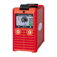
Trans Pocket 1500
Fronius Trans Pocket 1500 Manuals
Manuals and User Guides for Fronius Trans Pocket 1500. We have
1
Fronius Trans Pocket 1500 manual available for free PDF download: Service Instructions Manual
Fronius Trans Pocket 1500 Service Instructions Manual (231 pages)
Brand:
Fronius
| Category:
Welding System
| Size: 5 MB
Table of Contents
Deutsch
4
Sicherheit
3
Table of Contents
4
Sicherheitsvorschriften
8
Allgemeines
8
Umgebungsbedingungen
9
Verpflichtungen des Betreibers
9
Verpflichtungen des Personals
9
Bestimmungsgemässe Verwendung
9
Persönliche Schutzausrüstung
10
Gefahr durch Schädliche Gase und Dämpfe
10
Gefahr durch Funkenflug
10
Gefahren durch Netz- und Schweißstrom
11
Gefahren bei Geöffnetem Gehäuse
11
Vagabundierende Schweißströme
11
EMV-Maßnahmen
12
Besondere Gefahrenstellen
12
Die CE-Kennzeichnung
14
Urheberrecht
14
Kalibrieren von Stromquellen
14
Ersatz- und Verschleißteile
14
Veränderungen an der Stromquelle
14
Technische Daten - Leistungsschild
15
Leistungsschild
15
Kennzeichnung
15
Daten für den Schweißprozess
15
Einschaltdauer
16
Daten für die Energiezufuhr
17
Normkennlinie
17
Netzanschluss
18
Allgemeine Grundlagen - Funktionsprinzip
19
Inverterprinzip Allgemein
19
Resonanzkonverter
20
Serien-Resonanzkonverter
20
Serien-Parallel Resonanzkonverter
20
Erhöhung der Ausgangsspannung durch Serien-Parallel Resonanz
21
Begrenzung der Erhöhten Ausgangsspannung IM Leerlauf
21
Komplexe Regelung
21
Anwendung des Resonanzkonverter-Prinzips
22
Funktion Hot-Start und Anti-Stick
23
Messung und Regelung der Parameter Schweißstrom und Schweißspannung
23
Funktion TIG-Comfort-Stop
25
Gasströmung
26
VRD - Einrichtung zur Spannungsbegrenzung
27
Allgemeine Grundlagen - Umgang mit Bauteilen
28
Wärmeübertragung an Leistungsbauteilen
31
Allgemeine Grundlagen - Verpackung
31
Versand
31
Mess- und Prüfmittel
32
Werkzeug und Hilfsmittel
32
Historie
32
Allgemeines
32
Mess- und Prüfmittel, Werkzeug
32
Änderungen
32
Zusätzlich Benötigtes Werkzeug
33
Filteraufsatz
33
Filteraufsatz mit Filtereinsatz
33
Regelmäßige Kontrolle und Pflege
34
Wartung
34
Gehäuse Öffnen
34
Fehlerdiagnose und -Behebung
35
Sicherheit
35
Tabelle zur Fehlerbehebung
35
Mess-, Prüf- und Einstellarbeiten - Prüfung und Einstellung der Kenngrößen an den Schweißbuchsen
39
Allgemein
39
Maximalen Schweißstrom und Hot-Start Prüfen
39
Maximalen Schweißstrom Einstellen
40
Minimalen Schweißstrom Prüfen
40
Leerlaufspannung Prüfen
42
Dynamik und Anti-Stick Prüfen
42
Zyklustest
43
Transistormodul Prüfen
47
Sekundärdiode Prüfen
50
Potentiometer / Flachbandkabel Prüfen
50
Schutzleitertest
50
Isolationstest
51
Instandhaltungs- und Instandsetzungsarbeiten
53
Gesamtschaltplan
54
Gehäuse Öffnen
56
Einbauanleitung Print LCG15 und Sekundärdiode
56
Lieferumfang
56
Sicherheit
56
Sekundärdiode Ausbauen
58
Shunt Montieren und Leitungen Anschließen
61
Gehäuse Schließen
62
Einbauanleitung Print LCA15
63
Sicherheit
63
Lieferumfang
63
Zusätzlich Benötigtes Werkzeug
63
Gehäuse Öffnen
64
LCA15 Ausbauen
64
LCA15 Einbauen
66
Gehäuse Schließen
74
Sicherheit
78
Lieferumfang
78
Gehäuse Öffnen
86
Lieferumfang
86
Sicherheit
86
Temperaturfühler Ausbauen
87
Gehäuse Schließen
88
Einbauanleitung Lüfter
89
Sicherheit
89
Lieferumfang
89
Benötigtes Werkzeug
89
Gehäuse Öffnen
89
Lüfter Ausbauen
90
Lüfter Einbauen
91
Einbauanleitung Netzschalter und Netzkabel
93
Sicherheit
93
Lieferumfang
93
Gehäuse Öffnen
93
Netzschalter Ausbauen
93
Netzkabel Demontieren
93
Netzkabel Montieren
96
Netzschalter Einbauen
97
Lieferumfang
98
Sicherheit
98
Einbauanleitung Gasmagnetventil
98
Gasmagnetventil Ausbauen
99
Gehäuse Schließen
100
Benötigtes Werkzeug
101
Zusätzlich Benötigtes Werkzeug
101
Lieferumfang
101
Sicherheit
101
Einbauanleitung Potentiometer, Anschlussbuchse mit Dichtung für Fernbedienung
101
Gehäuse Öffnen
102
FPA15 Ausbauen
102
Dichtung für Anschlussbuchse Fernbedienung Ausbauen
104
Potentiometer und Anschlussbuchse für Fernbedienung Ausbauen
104
Potentiometer und Anschlussbuchse für Fernbedienung Einbauen
104
Dichtung für Anschlussbuchse Fernbedienung Einbauen
105
FPA15 Einbauen
106
Gehäuse Schließen
106
Lieferumfang
107
Sicherheit
107
Einbauanleitung Gehäusevorderseite mit Klebeetikett und Schweißbuchsen
107
Gehäuse Öffnen
108
FPA 15 Ausbauen
108
Dichtung für Anschlussbuchse Fernbedienung Ausbauen
109
Schweißbuchsen Ausbauen
110
Schweißbuchsen Einbauen
111
Dichtung für Anschlussbuchse Fernbedienung Einbauen
112
FPA15 Einbauen
113
Gehäuse Schließen
114
English
117
General Remarks
121
Safety Rules
121
Ambient Conditions
122
Obligations of Owner/Operator
122
Obligations of Personnel
122
Utilisation for Intended Purpose Only
122
Hazards from Flying Sparks
123
Hazards from Noxious Gases and Vapours
123
Personal Protective Equipment
123
Hazards from Mains and Welding Current
124
Hazards When the Machine Housing Is Open
124
Vagrant Welding Currents
124
EMC Precautions
125
Informal Safety Precautions
126
Safety Inspection
126
Safety Precautions at the Installation Location
126
Alterations to the Power Source
127
Calibration of Power Sources
127
CE-Marking
127
Copyright
127
Spares and Wearing Parts
127
Data Regarding Weld Process
128
Identification
128
Rating Plate
128
Technical Data - Rating Plate
128
Duty Cycle
129
Data Regarding Power Supply
130
Standard Characteristic
130
Mains Connection
131
General Basics - Functional Principle
132
Inverter Principle - General Remarks
132
Resonance Converter
132
Series Resonance Converter
133
Series-Parallel Resonance Converter
133
Complex Regulation
134
Increasing the Output Voltage by Means of Series-Parallel Resonance
134
Limiting the Increased Output Voltage in Open Circuit
134
Applying the Resonance Converter Principle
135
Hot-Start and Anti-Stick Functions
136
Measuring and Regulating the Parameters "Welding Current" and "Welding Voltage
136
TIG-Comfort-Stop" Function
138
Gas Flow
139
VRD - Voltage Reduction Device
140
General Basics - How to Handle Components
141
ESD Precautions
142
General Basics - Packaging
144
Heat Dissipation from Power Componentry
144
General Remarks
145
History
145
Measuring and Testing Equipment, Tools
145
Filter Attachment
146
Filter Attachment with Filter Insert
146
Care and Maintenance
147
Checking and Setting the Maximum Welding Amperage
147
Opening the Housing
147
Regular Checks and Care
147
Safety
148
Troubleshooting
148
Troubleshooting Table
148
Checking the Maximum Welding Amperage and Hot-Start
152
General Remarks
152
Measuring, Inspection and Adjustment Jobs - Checking and Setting the Parameters on the Welding Sockets
152
Checking the Minimum Welding Amperage
153
Setting the Maximum Welding Amperage
153
Checking the Open-Circuit Voltage
154
Check the Arc-Force and Anti-Stick
155
Cycle Test
156
Checking the Transistor Module
160
Checking the Potentiometer Ribbon Cable
163
Checking the Secondary Diode
163
PE Conductor Test
163
Insulation Test
164
Maintenance and Repair Work
166
Overall Circuit Diagram
167
Installation Instructions: LCG15 Board and Secondary Diode
169
Safety
169
Opening the Housing
170
Removing the LCG15 Board
170
Removing the Secondary Diode
171
Mounting the Shunt and Connecting the Leads
174
Closing the Housing
175
Installation Instructions: LCA15 Board
176
Safety
176
Scope of Supply
176
Tools Needed
176
Opening the Housing
177
Removing the LCA15 Board
177
Closing the Housing
182
Additional Tools Needed
183
Installation Instructions: FPA15 Board
183
Opening the Housing
183
Safety
183
Scope of Supply
183
Tools Needed
183
Removing the FPA15 Board
185
Closing the Housing
187
Installation Instructions: Varistor
188
Opening the Housing
188
Safety
188
Scope of Supply
188
Removing the Varistor
189
Closing the Housing
190
Additional Tools Needed
191
Installation Instructions: Transformer
191
Opening the Housing
191
Safety
191
Scope of Supply
191
Tools Needed
191
Removing the LCA15 Board
192
Removing the Transformer
193
Fitting the Transformer
194
Closing the Housing
198
Installation Instructions: Temperature Sensor
199
Opening the Housing
199
Safety
199
Scope of Supply
199
Tools Needed
199
Removing the Temperature Sensor
200
Closing the Housing
201
Installation Instructions: Fan
202
Opening the Housing
202
Safety
202
Scope of Supply
202
Tools Needed
202
Fitting the Fan
204
Removing the Fan
204
Closing the Housing
205
Installation Instructions: Mains Switch and Mains Cable
206
Safety
206
Scope of Supply
206
Tools Needed
206
Opening the Housing
207
Unplugging the Mains Leads
207
Removing the Mains Cable
208
Mounting the Mains Cable
209
Closing the Housing
210
Fitting the Mains Switch
210
Installation Instructions: Gas Solenoid Valve
211
Opening the Housing
211
Safety
211
Scope of Supply
211
Fitting the Gas Solenoid Valve
212
Removing the Gas Solenoid Valve
212
Closing the Housing
213
Installation Instructions: Potentiometer, Connection Socket + Seal for Remote Control Unit
214
Safety
214
Scope of Supply
214
Tools Needed
214
Opening the Housing
215
Removing the FPA15 Board
215
Closing the Housing
219
Installation Instructions: Front of Housing, with Adhesive Label and Welding Sockets
220
Safety
220
Scope of Supply
220
Tools Needed
220
Opening the Housing
221
Removing the FPA15 Board
221
Removing the Front of the Housing
223
Removing the Welding Sockets
223
Fitting the Front of the Housing
224
Fitting the Welding Sockets
224
Closing the Housing
227
Advertisement
Advertisement
Related Products
Fronius TransPocket 2500 Comfort
Fronius TransPocket 3500 Comfort
Fronius Trans Pocket 4000 CEL
Fronius Trans Pocket 5000 CEL
Fronius TransSteel 5000
Fronius TransTig 230i
Fronius TransTig 5000
Fronius TransTig 4000
Fronius TransTig 1700
Fronius TRANSTIG 2000
Fronius Categories
Inverter
Welding System
Welding Accessories
Battery Charger
Measuring Instruments
More Fronius Manuals
Login
Sign In
OR
Sign in with Facebook
Sign in with Google
Upload manual
Upload from disk
Upload from URL