Sign In
Upload
Manuals
Brands
Festo Manuals
Touch terminals
CPV -VI Series
Festo CPV -VI Series Manuals
Manuals and User Guides for Festo CPV -VI Series. We have
2
Festo CPV -VI Series manuals available for free PDF download: Manual
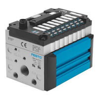
Festo CPV -VI Series Manual (165 pages)
CPV valve terminal
Brand:
Festo
| Category:
Touch terminals
| Size: 3.79 MB
Table of Contents
Contents and General Instructions
3
Table of Contents
5
Designated Use
7
Target Group
8
Service
8
Notes on the Use of this Manual
8
Variants of the CPV Valve Terminal
9
Manuals on the CP System
10
Manuals on the SPC200 Smart Positioning Controller
11
Danger Categories
12
Important User Instructions
12
Marking Special Information
13
List of Abbreviations
14
Product−Specific Terms and Abbreviations
15
1 Sysytem Summary
17
Description of Variants
19
Description of Components
22
Sizes of the CPV Valve Terminals
22
Max Number of Sub−Bases CPV Terminals with As−Interface Connection
22
Identification Code
23
Pneumatic Components
23
Valve Extension 5/3G (Only CPV10/14)
24
Identification Codes of the Pneumatic Components
24
Flow Control Valve or One−Way Flow Control Valve Extension
25
Vacuum Generator Plates
25
Separator Plate
26
Relay Plate
26
Pneumatic Multipin
27
Mounting Holes
27
Overview of Components
28
Components of the CPV Valve Terminal
28
Supplementary Components of the CPV Valve Terminal
29
Connecting, Display and Operating Elements
30
Electrical Connecting/Display Elements of CPV Valve Terminal IC
31
Electrical Connecting/Display Elements of CPV Valve Terminal with MP
32
Electrical Connecting/Display Elements of CPV Valve Terminal with CP
33
Electrical Connecting/Display Elements of CPV Terminal with as
34
2 Fitting
35
CPV Valve Terminal with Individual Tubing
37
Fitting Variants
37
Fastening Profile Sections for Fitting Onto a Wall
38
Itting Onto a Wall
38
Type of Mounting
38
Fitting Onto a Wall, Tightening Torques
39
Connecting the CPV Valve Terminal
40
Type of Mounting Rear
40
Type of Mounting Top
40
Dimensions of the Fastening Holes
41
Dimensions of the Wall Cut−Outs
42
Fitting Onto a hat Rail
43
Holes for Wall Fitting
43
Hat Rail Adapter, Tightening Torques
44
Hat Rails
44
Fitting the Valve Terminal on a hat Rail
45
Fitting Onto a Stand
46
Position of the Fastening Holes
46
Mounting on a Stand, Fastening Screws
47
Fitting the CPV Valve Terminal to the SIMATIC ET200X
48
Preparing for Fitting Onto the SIMATIC ET200X
49
Fitting the CPV Valve Terminal Onto the Siemens SIMATIC ET200X
50
CPV Valve Terminal with Pneumatic Multipin
51
Fitting the Pneumatic Multipin
52
Diameter of the Fastening Holes and Screw Size
52
Dimensions of Wall Cut−Out for Pneumatic Multipin
53
Fitting the Pneumatic Multipin (Rear Side)
55
Hole Dimensions for Rear Fitting
55
Fitting the CPV Valve Terminal to the Pneumatic Multipin
56
Fitting the Valve Extensions
57
Fitting the Identifier Support
58
Fitting the Manual Override Cover
59
3 Installation
61
Preparing the Compressed Air
63
Operation with Non−Lubricated Compressed Air
63
Operation with Lubricated Compressed Air
64
Setting the Lubricator
64
Checking the Lubricator Setting
65
General Connecting Methods
66
Laying the Tubing
66
Basic Information
67
Fitting the Tubing
67
Auxiliary Pilot Air
68
Connecting the CPV Valve Terminal
68
External Pilot Air
69
Internal Pilot Air
69
Connecting the Supply and Work Lines
71
CPV Valve Terminal
72
Sizes of the Pneumatic Connections
72
Common Lines with Non−Return Valves
73
Pressure Zones of the CPV Valve Terminals
74
Vacuum/Low Pressure Operation
74
Connecting the Electric Cables
76
Earthing Connections on the CPV Valve Terminal
77
Earthing the CPV Valve Terminal
77
Connecting Current−Consuming Devices to the Relay Plate
78
Fitting the Relay Output Sockets
78
Address Assignment of the Valves
79
CPV Valve Terminal with IC Connection
79
Fitting the Individual Connecting Sockets
80
CPV Valve Terminal with CP Connection
81
CPV Valve Terminal with Direct Connection
81
CPV Valve Terminal with Multipin or As−Interface Connection
81
Commissioning
83
Before Commissioning
85
General Instructions
85
Valve−Cylinder Combination with Slow Increase in Pressure
87
Commissioning Variants
88
Effects of Slow Start−Up Pressurization
88
Testing the Valves
88
Checking the Valve Functions
89
Manual Override
89
Assignment of Manual Overrides to the Pilot Solenoids
90
Designs of Manual Override
90
Carrying out the Test
91
Checking the Valve−Cylinder Combination
91
Non−Locking Actuation of the Manual Override
92
Locking Actuation of the Manual Override
94
Eliminating Faults
95
Function Impairment of the Pneumatic System
95
Impairment of Function
95
LED Display of the Valves
97
Pneumatic Operating States
97
LED Assignment
98
LED Display of the Relays
99
Meaning of the LED Display
99
LED Assignment of Relay Plate
100
Maintenance and Conversion
101
Cleaning/Replacing the Large Surface−Mounted Silencer
103
Tightening Torques for Large Surface−Mounted Silencer
103
Fitting/Removing CPV Valve Terminal Components
104
Maintenance and Conversion
104
Compatibility List of Valve Location Components
105
Loosen the Electrical Connections
106
Note the Following with the IC Connection
106
Removing Components from Valve Locations
106
Remove the CPV Valve Terminal from the Fastening Surface
107
Remove the Components
108
Removing the Valves
108
Position of the Tie Rods
109
Fitting Components in Valve Locations
110
Position and Designation of Seals with Pneumatic Spring Valves
111
Position of the Flat Seal on the Electrical Sub−Base
113
Flat Seal
114
Fitting the CPV Valve Terminal
115
Fitting the Pneumatic and Electrical Connections
115
Conversion from Non−Locking to Locking Manual Override
116
Safety Clip for the Manual Override
116
Converting the End Plates
117
Conversion to Internal or External Auxiliary Pilot Air
119
Conversion to Individual Tubing/Central Tubing
120
Conversion of the CPV Valve Terminal to Two Pressure Zones
121
Converting the CPV Valve Terminal to a Variant with Different Electrical Connections
122
CPV Valve Terminals with MP, As−Interface, DI and CP Connections
123
Technical Appendix
125
A. Technical Appendix
126
A.1 Technical Specifications
127
Technical Specifications Weight of the CPV Valve Terminal
129
Technical Specifications Medium and Pressure Ranges
130
Specifications Rated Flows, Valve Switching Times and Connection Sizes
131
Technical Specifications Electric Components
133
A.2 Accessories
134
Summary of Components
137
B. Summary of Components
138
B.1 Overview of Valve Sub−Bases and Vacuum Generator Plates
139
Overview Valve Sub−Bases with 2/2−Way Valves
139
Overview Valve Sub−Bases with 3/2−Way Valves
140
Overview Valve Sub−Bases with 5/2−Way Valves
141
Overview Valve Sub−Base or Function (5/3−Way Valves)
142
Overview Vacuum Generator Plates
143
B.2 Overview of End Plates
144
Position of End Plate Part Number
144
Overview End Plate Identification
145
End Plates for Internal Auxiliary Pilot Air
147
End Plates with Large Surface−Mounted Silencer
148
End Plates for External Auxiliary Pilot Air
149
End Plate Pairs for Internal Auxiliary Pilot Air/Pneumatic Multipin
151
C. Index
158
C.1 Index
159
Advertisement
Festo CPV -VI Series Manual (118 pages)
Compact Performance CPV valve terminal, Pneumatics
Brand:
Festo
| Category:
Touch terminals
| Size: 2.94 MB
Table of Contents
Table of Contents
5
Designated Use
7
Target Group
7
Important User Instructions
8
Information on this Manual
10
Abbreviations
13
1 System Overview
15
Summary of Variants
17
Description of Components
22
2 Fitting
31
CPV Valve Terminal with Individual Tubing
33
Fitting Onto a Wall
34
Fitting Onto a hat Rail
38
Fitting with Feet
41
Fitting the CPV Valve Terminal Onto the SIMATIC ET 200X
43
CPV Valve Terminal with Pneumatic Multiple Connector Plate
46
Fitting the Pneumatic Multiple Connector Plate
50
Fitting the CPV Valve Terminal Onto the Pneumatic Multiple Connector Plate
51
Fitting the Designation Support
52
3 Installation
53
General Connecting Principles
55
Connecting the CPV Valve Terminal
57
Auxiliary Pilot Air
58
Connecting the Supply and Work Tubing
60
Connecting the Electrical Cables
63
4 Commissioning
69
General Instructions
71
Testing the Valves
72
Locating Faults
78
5 Maintenance and Conversion
83
Fitting/Removing CPV Valve Terminal Components
85
Removing Components from Valve Locations
86
Fitting Components into the Valve Locations
89
Conversion from Automatic Reset Manual Override to Locking Manual Override
95
Conversion from Internal to External Pilot Air
96
Conversion from Individual to Central Tubing
102
Converting the CPV Valve Terminal to Two Pressure Zones
103
Converting the CPV Valve Terminal to Different Electrical Connections
104
Technical Appendix
107
Accessories
109
A.1 Accessories
109
Technical Specifications
110
A.2 Technical Specifications
110
Index
115
A.3 Index
115
Advertisement
Related Products
Festo CPV VI Series
FESTO CPV-VI Series
Festo CPV-SC Series
Festo CPV14
Festo CPV10/14-VI-BG-RWL-B
Festo CPV10-VI-BG-ET200X
Festo CPV18-VI-BG-RW
FESTO CPV14-VI
Festo CPV GE-SD-8 Series
Festo CPV10-GE-IL-8
Festo Categories
Industrial Equipment
Control Unit
Controller
Touch terminals
DC Drives
More Festo Manuals
Login
Sign In
OR
Sign in with Facebook
Sign in with Google
Upload manual
Upload from disk
Upload from URL