Sign In
Upload
Manuals
Brands
Emerson Manuals
Measuring Instruments
Daniel 3414
Emerson Daniel 3414 Manuals
Manuals and User Guides for Emerson Daniel 3414. We have
4
Emerson Daniel 3414 manuals available for free PDF download: Operation Manual, Instructions For Use, Maintenance And Installation Manual, Maintenance And Troubleshooting Manual
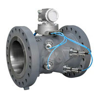
Emerson Daniel 3414 Operation Manual (192 pages)
Gas Ultrasonic Flow Meters
Brand:
Emerson
| Category:
Measuring Instruments
| Size: 2.17 MB
Table of Contents
Table of Contents
9
Preface
17
Section 1: Startup Checklist
17
Startup Checklist
17
Table 1-1 Equipment and Information Checklist
17
Section 2: Setup Meter Communications
19
Daniel Meterlink Utilities
19
Setup the Meter Directory
20
Connect to the Meter
23
Collect as Found Logs and Reports
24
Customize Daniel Meterlink Settings
25
Figure 2-1 Program Settings
25
Setup Modbus Communications
26
Table 2-1 Modbus Communication Parameters
26
Setup HART® Communications
27
Setup the Meter in a Deltav System
27
Section 3: Optional Feature Keys
29
Overview
29
Obtaining Optional Keys
29
GC Interface Key
30
AGA10 Key (Sound Velocity Calculation)
30
Continuous Flow Analysis (CFA) Key
30
Key Status
30
Configure Optional Keys
31
Section 4: Flow Measurement
33
Figure 4-1 Model 3414 Transit-Time Measurement Principle
33
Transducer Timing Control
34
Figure 4-2 Models 3412 or 3411 Measurement Principle
34
Figure 4-3 Signal Analyzer - Update Rate, Stack Size, Filter and Emission Rate
34
Terminology
35
Signal Processing
36
Stacking
36
Filtering
36
Batch Cycle Processing
37
Table 4-1 Actual Meter Update Period
37
Smoothing
38
Acquisition Mode
38
Re-Acquisition
38
Chord Gas and Sound Velocity Measurements
39
Average Sound Velocity
40
Optional AGA10 Sound Velocity Calculation and Comparison
40
Average Weighted Gas Flow Velocity
41
Table 4-2 AGA10 Calculation Status
41
Average Weighted Flow Velocity Using Chord Proportions
42
Volumetric Flow Rate
45
Raw Volumetric Flow Rate
45
Flow-Condition Volumetric Flow Rate
45
Pressure-Effect Expansion Correction
46
Temperature-Effect Expansion Correction
47
Profile-Effect Correction
48
Reynolds Number
49
Base-Condition Volumetric Flow Rate
50
Volume
50
Energy Rate and Totals
51
Table 4-3 Volume Accumulation Data Points
51
Mass Rate and Totals
52
Table 4-4 Energy Total Data Points
52
3410 Series Gas Flow Meter Characterizations
53
Table 4-5 Mass Total Data Points
53
Section 5: Calibrate and Configure the Meter
55
Calibration Methods
55
Dry Calibration
55
Figure 5-1 Calibration - Meter Factors Page
56
Table 5-1 Data Points for Dry Calibration
57
Wet Calibration
59
Table 5-2 Data Points for Wet Calibration Method
59
Wet Calibration Piece-Wise Linearization
60
Figure 5-2 Calibration - Meter Factor: None
60
Figure 5-3 Calibration - Meter Factor: Piecewise Linearization
61
Table 5-3 Data Points for Piece-Wise Linearization Calibration
62
Third-Order Polynomial
63
Figure 5-4 Calibration - Meter Factor: Polynomial
63
Table 5-4 Data Points for Polynomial Wet Calibration
64
No Wet Calibration
65
Triggered Delta Volumes
65
Table 5-5 Configure Operational Parameters
66
Calibrate Analog Inputs and Outputs
68
Figure 5-5 Offset Calibration
69
Calibrate Meter Factors
71
Flow Calibration
71
Figure 5-6 Gating Configuration Parameter Edge Gated, Active High
71
Figure 5-7 Gating Configuration Parameter Edge Gated, Active Low
72
Figure 5-8 Gating Configuration Parameter State Gated, Active High
72
Figure 5-9 Gating Configuration Parameter State Gated, Active Low
72
Configure Frequency/Digital Output Sources
73
Table 5-6 Frequency/Digital Outputs Possible Configurations
74
Figure 5-10 CPU Module - Frequency/Digital Outputs Common Ground
75
Figure 5-11 CPU Module - Frequency/Digital Outputs Common Ground - Type 4
76
Configure Frequency Outputs
77
Configure Digital Input/Outputs
79
Figure 5-12 Meter Outputs Test Page
80
Outputs Test Mode
80
Configure HART Outputs
81
Configure the Four Dynamic Variables
81
Configure the Device Identification
82
Configure the HART Units
82
Configure Meter Corrections
82
Flow Profile Correction
82
Temperature Expansion Correction
82
Pressure Expansion Correction
82
Configure Temperature and Pressure
83
Flow-Condition Pressure and Temperature
83
Table 5-7 Flow-Condition Pressure and Temperature Data Source
84
Configure the Temperature Parameters for the Meter
85
Configure the Pressure Parameters for the Meter
85
Configure Gas Chromatograph Parameters
86
Gas Properties
87
Table 5-8 Fixed Gas Composition Data Points
88
Table 5-9 GC-Reported Gas Composition Data Points
89
Table 5-10 In-Use Gas Composition Data Points
90
Table 5-11 C6+ Breakdown to Standard Components by Component ID
91
Table 5-12 Gas Chromatograph Sim 2251 Registers
92
Table 5-13 Supported Component Ids
93
Data Polling
94
Gas Property Data
94
Table 5-14 GC Communication Status List
94
GC Alarm Handling
95
GC Data Validity
95
Table 5-15 GC-Read Gas Property Invalid Conditions
95
Configure AGA8 Parameters
96
Configure Continuous Flow Analysis Parameters
97
Set Baseline Parameters
97
Configure the Local Display
98
Figure 5-13 Field Setup Wizard - Local Display
98
Table 5-16 Local Display Labels, Descriptions and Valid Units
99
Section 6: Archive Logs
103
Daily and Hourly Log Data Point Actions
103
Daily Log
104
Table 6-1 Daily Log Content
104
Hourly Log
108
Table 6-2 Hourly Log Action Type
108
Audit Log
111
Table 6-3 Audit Log AGA 8 Group Monitored Data Points
112
Table 6-4 Audit Log AGA 10 Group Monitored Data Points
112
Table 6-5 Audit Log Baseline Group Monitored Data Points
112
Table 6-6 Audit Log Calibration Group Monitored Data Points
113
Table 6-7 Audit Log Chord Proportions Group Monitored Data Points
116
Table 6-8 Audit Log Colocated Meter Group Monitored Data Point
116
Table 6-9 Audit Log Communication Group Monitored Data Point
116
Table 6-10 Audit Log Data Logging Group Monitored Data Points
116
Table 6-11 Audit Log Expansion Correction Group Monitored Data Points
117
Table 6-12 Audit Log Flow Analysis Group Monitored Data Points
117
Table 6-13 Audit Log Frequency, Digital and Analog Group Monitored Data Points
118
Table 6-14 Audit Log Gas Chromatograph Group Monitored Data Points
120
Table 6-15 Audit Log General Group Monitored Data Points
121
Table 6-16 Audit Log HART Data Group Monitored Data Points
122
Table 6-17 Audit Log Indicators Group Monitored Data Points
123
Table 6-18 Audit Log Local Display Group Monitored Data Points
123
Table 6-19 Audit Log Meter Information Group Monitored Data Points
124
Table 6-20 Audit Log Pressure and Temperature Group Monitored Data Points
124
Table 6-21 Audit Log Reynolds Number Calculation Group Monitored Data Point
125
Table 6-22 Audit Log Signal Processing Group Monitored Data Points
125
Determining Meter Power-Up and Power-Down Times
126
Table 6-23 Audit Log Tracking Group Monitored Data Points
126
Event Log: Alarm/Audit
127
Table 6-24 Alarm Log Monitored Data Points
128
Options for Reading Audit, Alarm, And/Or System Log Records
129
Options for Reading Daily And/Or Hourly Log Records
129
Reading Log Records
129
System Log
129
Collecting and Viewing Log Records
130
Collecting Logs
131
Figure 6-2 Maintenance Logs
131
Figure 6-3 Log Complete Dialog
132
Figure 6-4 Microsoft® Excel Report View Toolbar
132
Figure 6-5 Microsoft® Excel Charts View
133
Rev E January
133
Figure 6-6 Microsoft® Excel Inspection Report View
134
Figure 6-7 Microsoft® Excel Meter Config View
135
Figure 6-8 Microsoft® Excel Raw Data View
136
Collect Meter Archive Logs
137
Figure 6-9 Meter Archive Logs
137
Section 7: Tools Commands
139
Edit/Compare Configuration Parameters
139
Figure 7-2 Edit/Compare Configuration Parameters
139
Figure 7-3 Edit/Compare Configuration Parameter Changes
140
Waveform Viewer
141
View the Transducer Waveforms
141
Figure 7-4 Waveform Viewer - Time Domain
142
Navigate the Waveform Viewer
143
Figure 7-5 Waveform Viewer - Frequency Domain
143
Table 7-1 Waveform Chart Keyboard Commands
145
Gas SOS Calculator
146
Calculate SOS for the Gas Composition
146
Figure 7-6 Gas SOS Calculator
146
Outputs Test
148
Transducer Swap-Out
148
Baseline Viewer
149
Figure 7-7 Baseline Viewer
149
Read the Baseline Viewer Gauge Values
150
Table 7-2 Baseline Viewer Gauge Values
150
Upgrade Program Components
151
Figure 7-8 Program Download Dialog
151
Error Recovery for Program Download Failure
152
Communications Analyzer
154
Figure 7-9 Communications Analyzer
154
Appendix A: Conversion Factors
155
Conversion Factors Per Unit of Measurement
155
Table A-1 Conversion Factors Per Unit of Measurement
155
Appendix B: Miscellaneous Equations
157
Miscellaneous Conversion Factors
157
B.2 Chord "L" Dimension Calculation
159
Appendix C: Troubleshooting Comm., Mech., and Elec
161
C.1 Communications Troubleshooting
161
C.2 Mechanical/Electrical Troubleshooting
163
Table C-1 Mechanical/Electrical Troubleshooting
163
Appendix D: Flow Rate Summary Charts
165
Flow Rate Summary Charts
165
Appendix E: Write-Protected Configuration Parameters
169
Write-Protected Configuration
169
Table E-1 Write-Protected Configuration Parameters
169
Appendix F: Engineering Drawings
183
3410 Series Engineering Drawings
183
Appendix G: Index
189
G.1 Manual Index
189
Advertisement
Emerson Daniel 3414 Maintenance And Troubleshooting Manual (108 pages)
Gas Ultrasonic Flow Meters
Brand:
Emerson
| Category:
Measuring Instruments
| Size: 3.56 MB
Table of Contents
Table of Contents
9
Chapter 1 Maintenance
11
Precautions for Meter Maintenance
11
Field Hydrostatic Pressure Testing Procedures
12
T-Slot Transducer Assembly and Mount
13
Routine Maintenance
14
Maintenance Logs and Reports
14
Pipeline Cleaning Maintenance
18
Visual Inspection
18
Chapter 2 Troubleshooting
21
Meter Status Alarms
21
Check Status
22
System Alarm
23
Chord A, Chord B, Chord C and Chord D Alarm
23
Field I/O Alarm
23
Validity Alarm
24
Comms Alarm
24
Communications
24
Troubleshooting the Meter
24
Meter Maintenance
36
Unable to Connect Direct Serial or External Serial Modem
45
Unable to Connect to Meter
46
Ethernet Connections
46
Direct Serial Connections
46
Troubleshoot Maintenance Log Files and Trend Files
46
Files Do Not Appear in Workbook
46
Microsoft ® Excel ® Log/Export Options Are Not Available
47
Maintenance Logs or Trend Files Are Not Created
47
Chapter 3 Meter Repairs
51
Prior Precautions
51
Field Hydrostatic Pressure Testing Procedures
53
T-Slot Transducer Assembly and Mount
54
T-Slot Transducer Removal and Installation Procedures
55
Transducer Removal with Extractor Tool
56
Transducer Removal Without Extractor Tool
58
Transducers Installation Procedure
61
Replace Transformers Procedure
63
Modifying the Calibration Parameters
64
Transducer Holder Removal and Installation
66
Remove the Transducer Holder with the Extractor Tool
67
Remove the Transducer Holder Without the Extractor Tool
67
Install the Transducer Holder with the Extractor Tool
69
Install the Transducer Holder Without the Extractor Tool
69
Transducer Cable Removal and Installation
72
Remove Transducer Cables
73
Install Transducer Cables
74
Replace the Meter Electronics
78
Replace the CPU Module or Optional I/O Module
79
Replace the Fuse
82
Replace Backplane, I.S. Barrier or Power Supply Board
83
Replace the Adquisition Module
90
Appendix A Conversion Factors
97
Conversion Factors Per Units of Measurement
97
K-Factor and Inverse K-Factor
98
Appendix B Engineering Drawings
101
Daniel 3410 Series Ultrasonic Flow Meter Drawings
101
Emerson Daniel 3414 Instructions For Use, Maintenance And Installation Manual (110 pages)
Gas Ultrasonic Flow Meters
Brand:
Emerson
| Category:
Measuring Instruments
| Size: 4.2 MB
Table of Contents
Table of Contents
9
Chapter 1 Maintenance
11
Precautions for Meter Maintenance
11
Field Hydrostatic Pressure Testing Procedures
12
Routine Maintenance
14
Chapter 2 Troubleshooting
21
Meter Status Alarms
21
Troubleshooting the Meter
24
Troubleshoot Maintenance Log Files and Trend Files
45
Chapter 3 Meter Repairs
51
Precautions Prior to Repairs
51
Field Hydrostatic Pressure Testing Procedures
53
T-Slot Transducer Removal and Installation Procedures
55
T-Slot Transducer Holder Removal and Installation
65
Transducer Assembly Removal and Installation
71
Transducer Capsule Assembly Removal and Installation
74
Transducer Housing Removal and Installation
79
Transducer Cable Removal and Installation
81
Replace the Meter Electronics
87
Adquisition Module Replacement
97
Appendix A Conversion Factors
103
Conversion Factors Per Units of Measurement
103
K-Factor and Inverse K-Factor
104
Appendix B Engineering Drawings
105
Daniel 3410 Series Ultrasonic Flow Meter Drawings
105
Advertisement
Emerson Daniel 3414 Maintenance And Troubleshooting Manual (90 pages)
Gas Ultrasonic Flow Meters
Brand:
Emerson
| Category:
Industrial Equipment
| Size: 8.03 MB
Table of Contents
Table of Contents
3
Chapter 1 Maintenance
5
Precautions for Meter Maintenance
5
Field Hydrostatic Pressure Testing Procedures
6
Routine Maintenance
7
Chapter 2 Troubleshooting
13
Meter Status Alarms
13
Troubleshooting the Meter
16
Troubleshoot Maintenance Log Files and Trend Files
35
Chapter 3 Meter Repairs
39
Precautions Prior to Repairs
39
T-Slot Transducer Removal and Installation
42
T-Slot Transducer Holder Removal and Installation
50
T-200 Transducer Assembly Removal and Installation
54
T-200 Transducer Capsule Assembly Removal and Installation
59
T-200 Transducer Housing Removal and Installation
59
Transducer Cable Removal and Installation
61
Replace the Meter Electronics
67
Acquisition Board Replacement
77
Appendix A Conversion Factors
83
Conversion Factors Per Units of Measurement
83
K-Factor and Inverse K-Factor Conversions
84
Appendix B Engineering Drawings
85
Daniel 3410 Series Ultrasonic Flow Meter Drawings
85
Advertisement
Related Products
Emerson Daniel 3415
Emerson Daniel 3417
Emerson Daniel 3416
Emerson Daniel 3410 Series
Emerson Daniel 3412
Emerson Daniel 3411
Emerson Daniel 3418
Emerson Rosemount 3051 CF Series
Emerson Daniel 3814
Emerson Daniel 3818
Emerson Categories
Controller
Control Unit
Transmitter
Measuring Instruments
Fan
More Emerson Manuals
Login
Sign In
OR
Sign in with Facebook
Sign in with Google
Upload manual
Upload from disk
Upload from URL