Sign In
Upload
Manuals
Brands
DYNACO Manuals
Amplifier
Stereo 120
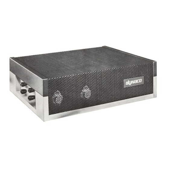
DYNACO Stereo 120 Manuals
Manuals and User Guides for DYNACO Stereo 120. We have
3
DYNACO Stereo 120 manuals available for free PDF download: Updating Instructions, Manual
DYNACO Stereo 120 Updating Instructions (32 pages)
SOLID STATE SUPER HEATSINK VERSION
Brand:
DYNACO
| Category:
Amplifier
| Size: 4.47 MB
Table of Contents
Table of Contents
2
Table of Figures
3
Section 1: about this Manual
4
Who Should Attempt this Project
4
Tools You'll Need
4
Project Overview
5
Important Safety Notes
5
Section 2: Checking the Stereo 120 Power Supply
6
Opening the Amplifier
6
Check the Power Supply Voltages
6
Figure 1-Location of the Four Screws that Hold the Cover to the Base
6
Section 3: Saving the Stuff that Should be Saved
7
Cutting the Wires on the Old Amplifier Modules
7
Removing the LEFT Channel Module
7
Removing the RIGHT Channel Module
8
Figure 2-Location Diagram for Cutting Wires
9
Figure 3-After the Amplifier Modules Have Been Removed
10
Removing C7 RIGHT
11
Removing C7 LEFT
11
Removing the Output Zobel Networks
11
Figure 4- Removal of Components Is Completed
12
Section 4: Troubleshooting the Stereo 120 Power Supply
13
Prepare and Connect the Test Load
13
Test the Power Supply
13
Figure 5-Connecting a Test Load to the Power Supply
13
Just in Case - Trouble Shooting
14
The Voltage Is Much more than 78 Volts
14
The Voltage Is Much Less than 66 Volts
14
There's no Voltage at All
14
Section 5: Building the Updated Circuit Boards
15
Install the Resistors
15
Figure 6-The First Four Resistors Are Installed with Leads Bent on the Back Side, but Not yet
15
Figure 7-Leads Soldered and Clipped
16
Install the Small Capacitors and the Diodes
17
Figure 8-Showing LED Cathode Orientation
17
Last Capacitors and the Transistors
18
Winding the Output Inductor
18
Solder the LM3886 into the Board
19
Figure 9-Starting to Wind the Output Inductor
19
Figure 10-Finishing Step for the Output Inductor
19
Figure 11-Showing Method of Attaching Brackets to the PCB
20
Figure 12-Template for Checking Mounting Height of LM3886
21
Figure 13-LM3886 Installation Step Three, Just the Corner Pins Are Soldered
21
Final Inspection of the Circuit Board
22
Figure 14-The LM3886 Sits up off the Board to Avoid Shorts between the Front and Back
22
Mounting the Updated Amplifier Board to the Super Heat Sink
23
Figure 15-Mounting Assembled PCB to Super Heat Sink
23
Figure 16-A Completed Amplifier Module
24
Figure 17-Showing Detail of Attaching Power Wiring Harness to C12
24
Figure 18-Showing the Final Wiring (Shown with Original, Rather than Super Heatsinks)
24
Section 6: Wiring in the Updated Amplifier Modules
25
Building and Installing the Power Wiring Harness
25
Figure 19-Final Wiring Viewed from the Other Side of the Amplifier (Shown with Original, Rather than Super Heat Sinks)
25
Building and Installing the Ground Wiring Harness
26
Figure 20-Wiring Harness
26
Wiring the Inputs
27
Wiring the Outputs
27
Connecting the Left Channel Amplifier Module
27
Figure 21-Ground Wiring Harness
27
Connecting the Right Channel Amplifier Module
28
Making the Speaker Binding Posts User Friendly
29
Section 7: Testing the Completed Amplifier
29
Test #1
29
Test #2
30
Test #3
30
Test #4
30
Figure 22-Schematic of Amplifer Module
31
Resistor Color Code
32
Figure 23-Demonstrating the Resistor Color Code
32
Advertisement
DYNACO Stereo 120 Updating Instructions (32 pages)
SOLID STATE
Brand:
DYNACO
| Category:
Amplifier
| Size: 1.68 MB
Table of Contents
Table of Contents
2
Section 1: about this Manual
4
Who Should Attempt this Project
4
Tools You'll Need
4
Project Overview
4
Important Safety Notes
5
Section 2: Saving the Stuff that Should be Saved
6
Opening up the Amplifier
6
Cutting the Wires on the Old Amplifier Modules
6
Removing the LEFT Channel Module
6
Figure 1-Location of the Four Screws that Hold the Cover to the Base
6
Removing the RIGHT Channel Module
7
Figure 2-Location Diagram for Cutting Wires
9
Figure 3-After the Amplifier Modules Have Been Removed
10
Removing C7 RIGHT
11
Removing C7 LEFT
11
Removing the Output Zobel Networks
11
Figure 4- Removal of Components Is Completed
12
Salvaging the Heat Sinks from the Amplifier Modules
13
Section 3: Checking the Stereo 120 Power Supply
13
Prepare and Connect the Test Load
13
Figure 5- Separating Heat Sinks and Circuit Boards
13
Test the Power Supply
14
Just in Case - Trouble Shooting
14
The Voltage Is Much more than 75.6 Volts
14
The Voltage Is Much Less than 68.4 Volts
14
Figure 6-Connecting a Test Load to the Power Supply
14
There's no Voltage at All
15
Section 4: Building the Updated Circuit Boards
16
Install the ¼ Watt Resistors
16
Figure 7-The First Four Resistors Are Installed with Leads Bent on the Back Side, but Not yet
16
Figure 8-Leads Soldered and Clipped
17
Install the Small Capacitors and the Diodes
18
Last Capacitors and the Transistors
19
Figure 9-Showing LED Cathode Orientation
19
Winding the Output Inductor
20
Figure 10-Starting to Wind the Output Inductor
21
Figure 11-Finishing Step for the Output Inductor
21
Solder the LM3886 into the Board
22
Figure 12-LM3886 Installation Step One, Just the Corner Pins Are Soldered
22
Figure 13-The LM3886 Sits up off the Board to Avoid Shorts between the Front and Back
22
Final Inspection of the Circuit Board
23
Mounting the Updated Amplifier Board to the Heat Sink
24
Figure 14-Attaching First Bracket to the Board
24
Figure 15-Both Brackets Attached to the Board
24
Figure 16-Circuit Board Mounted to Heat Sink
25
Figure 17-A Completed Amplifier Module
25
Section 5: Wiring in the Updated Amplifier Modules
26
Building and Installing the Power Wiring Harness
26
Figure 18-Wiring Harness
26
Building and Installing the Ground Wiring Harness
27
Wiring the Inputs
27
Figure 19-Ground Wiring Harness
27
Wiring the Outputs
28
Making the Speaker Binding Posts User Friendly
28
Figure 20-Sometimes the Input Connector Needs to be Bent to Clear the PCB
28
Section 6: Testing the Completed Amplifier
29
Figure 21-Schematic of Amplifer Module
31
Resistor Color Code
32
Figure 22-Demonstrating the Resistor Color Code
32
DYNACO Stereo 120 Manual (10 pages)
Installing the Really Big Heatsink for the Power Supply
Brand:
DYNACO
| Category:
Amplifier
| Size: 4.74 MB
Table of Contents
Table of Contents
2
Table of Figures
2
Section 1: about this Manual
3
Who Should Attempt this Project
3
Tools You'll Need
3
Project Overview
3
Important Safety Notes
4
About Components
4
Recommended Solder
4
Section 2: Removing the PSUG Power Supply and Stock Heatsink
4
Opening the Amplifier
4
Remove the PSUG Power Supply and Heatsink
5
Separate the PSUG and the Heatsink
5
Figure 1-Location of the Four Screws that Hold the Cover to the Base
5
Figure 2-Remove the Two Screws that Hold the Heatsink to the Chassis
5
Figure 3-Install the Male-Female Standoffs
6
Replace 3 Components to Increase the Power Delivered
6
Add a Mounting Hole to the Bottom of the Chassis
7
Figure 4-Showing Locations of C3, R3, and R11
7
Mount the Power Supply to the Really Big Heat Sink
7
Figure 5-Layout for Added Mounting Hole
8
Figure 6-Screw Sizes to Mount PSUG, Remember to Tighten the Screws
8
Figure 7-Use 6-32X3/8" Screws to Mount the Heatsink
9
Inspect for Clearance
9
Mount the Psug/Really Big Heat Sink Assembly to the Chassis
9
Reassemble the Amplifier
9
Testing the Result
9
Resistor Color Code
10
Figure 8-Demonstrating the Resistor Color Code
10
Advertisement
Advertisement
Related Products
Dynaco Stereo 80
Dynaco Stereo 70
DYNACO Stereo 400
DYNACO Stereo 410
DYNACO Stereo 416
DYNACO Dynakit ST35
DYNACO MARK VI
DYNACO PAS-2
Dynaco PAS-4
DYNACO PAT-4
DYNACO Categories
Amplifier
Tuner
Power Supply
Stereo System
Control Panel
More DYNACO Manuals
Login
Sign In
OR
Sign in with Facebook
Sign in with Google
Upload manual
Upload from disk
Upload from URL