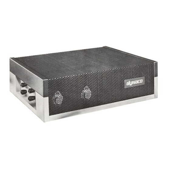
DYNACO Stereo 120 Manual
Installing the really big heatsink for the power supply
Hide thumbs
Also See for Stereo 120:
- Updating instructions (32 pages) ,
- Updating instructions (32 pages)

Related Manuals for DYNACO Stereo 120


Summary of Contents for DYNACO Stereo 120
- Page 1 DYNACO STEREO 120 Installing the Really Big Heatsink for the Power Supply © 2019 AkitikA, LLC All rights reserved Revision 1p03 February 21, 2019 Page 1 of 10...
-
Page 2: Table Of Contents
Table of Contents Table of Contents ........................ 2 Table of Figures ........................2 Section 1: About this Manual ..................... 3 Who Should Attempt this Project? ................. 3 Tools You’ll Need......................3 Project Overview ......................3 Important Safety Notes ....................4 About Components ...................... -
Page 3: Section 1: About This Manual
This manual gives you the information you need to replace the original power supply heatsink in a Dynaco Stereo 120 Solid State Power Amplifier with the Really Big Heat Sink. This kit allows your Stereo 120 to deliver more power, particularly at low frequencies, while running cooler. -
Page 4: Important Safety Notes
Important Safety Notes By purchasing this kit, you have agreed to hold AkitikA, LLC harmless for any injuries you may receive in its assembly and/or use. To prevent injuries: Wear safety glasses when soldering to prevent eye injuries. Always unplug the power before working on the amplifier. ... -
Page 5: Remove The Psug Power Supply And Heatsink
Figure 1-Location of the four screws that hold the cover to the base 3. Holding both the top and bottom of the amplifier, flip it over. 4. Lift the perforated metal top off the amplifier. Remove the PSUG power supply and heatsink Figure 2-Remove the two screws that hold the heatsink to the chassis Remove the two screws that hold the PSUG/Heat-sink combination to the floor of the chassis. -
Page 6: Replace 3 Components To Increase The Power Delivered
3. Unscrew the three male-female standoffs from the stock heatsink. a. Keep the three male-female standoffs. They will be re-used shortly. b. The three keps nuts will no longer be used. 4. Transfer the three male-female standoffs to the Really Big Heat Sink, installing them as shown in Figure 3. -
Page 7: Add A Mounting Hole To The Bottom Of The Chassis
Figure 4-Showing locations of C3, R3, and R11 If your PSUG was shipped before the end of 2018, it won’t have the gray 1µOK100 capacitor, but the locations of the changed components are still the same. Add a mounting hole to the bottom of the chassis To complete the new mounting arrangement, you’ll need to add a 9/64”... -
Page 8: Figure 5-Layout For Added Mounting Hole
a. Use the 6-32x3/8” screw from the previous mounting arrangement to fasten the power MOSFET to the heatsink. b. Use the supplied 6-32x1/4” sem screws (with built-in lockwashers) to fasten the PSUG to the really big heat sink. Figure 5-layout for added mounting hole Figure 6-screw sizes to mount PSUG, remember to tighten the screws Page 8 of 10... -
Page 9: Mount The Psug/Really Big Heat Sink Assembly To The Chassis
Mount the PSUG/Really Big Heat Sink Assembly to the Chassis Mount the PSUG/Really Big Heat Sink assembly to the chassis using two 6-32x3/8” screws. One of the screws goes into the newly drilled hole. The other screw goes into the slot. -
Page 10: Resistor Color Code
Resistor Color Code Figure 8-demonstrating the resistor color code Here’s an extreme close-up of a ¼ W metal film 20K (20,000) Ohm resistor, designated by the standard resistor color code. The colors map to numbers: Color Number Black Brown Orange Yellow Green Blue...
Need help?
Do you have a question about the Stereo 120 and is the answer not in the manual?
Questions and answers