Sign In
Upload
Manuals
Brands
DYNACO Manuals
Amplifier
PAT-4
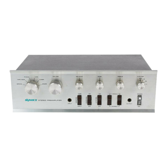
DYNACO PAT-4 Manuals
Manuals and User Guides for DYNACO PAT-4. We have
3
DYNACO PAT-4 manuals available for free PDF download: Assembly Manual
DYNACO PAT-4 Assembly Manual (23 pages)
PHONO UPGRADE
Brand:
DYNACO
| Category:
Amplifier
| Size: 4.83 MB
Table of Contents
Table of Contents
2
Table of Figures
2
Section 1: about this Manual
3
Who Should Attempt These Projects
3
Tools and Supplies You'll Need
4
Recommended Solder
4
Project Overview
4
Important Safety Notes
4
Section 2: about the Phono Preamp Upgrade
5
Effects of the Modification
5
Before You Begin
5
Prerequisites
5
Preparing to Remove the Circuit Boards
6
PC Board Modifications
7
Figure 1-Stock PCB (before Upgrade)
8
Figure 2-Stock PCB (after Upgrade)
8
Figure 3-Detail of R2-C3-White-Wire Connection
9
Figure 4-Preparing C4 for Installation
10
Adding R30 if Your PCB Doesn't Have a Place for It
11
Installing the DRD4 Kit
11
PAT-4 PWR Modifications (Optional)
11
Figure 5-Insert R30 in from the Back of the Board
11
Figure 6-Final Step of R30 Installation in those Cases Where Holes Don't Already Exist on
11
Inspection and Preliminary Reassembly
12
Figure 7-Both Pcbs Reassembled Onto U Brackets, Ready for Installation
12
Final Wiring and Reassembly
13
If You Want 5 High Level Inputs and 1 Phono Input
13
Figure 8-Changes to Grounds for 5 High Level Input Version of PAT-4
14
Figure 9-Adding Shielded Cable as Part of the 5 High Level Input Modification
16
Final Sanity Checks
17
Prepare to Reconnect Your PAT-4 to Your Music System
17
Appendix 1: the Toothpick Trick
17
Appendix 2: First Class De-Soldering
18
Schematics
19
Figure 10-Schematic Shows Phono Preamp with Modifications
19
Figure 11-Schematic When Modified for 1 Phono and 5 High Level Inputs
20
Record Playing Reminders
21
Appendix 3 - Preparing a Shielded Cable End
22
Advertisement
DYNACO PAT-4 Assembly Manual (20 pages)
UPGRADES for Line amp distortion reducer Tone control switch
Brand:
DYNACO
| Category:
Amplifier
| Size: 3.2 MB
Table of Contents
Table of Contents
2
Table of Figures
2
Section 1: about this Manual
3
Who Should Attempt These Projects
3
Tools You'll Need
3
Project Overview
4
Line Amp Distortion Reducer
4
Tone Control Switch
4
Important Safety Notes
4
Section 2: Line Amp Distortion Reducer
5
Line Amp Characteristics
5
How the Distortion Reduction Works
5
The Modification in a Nutshell
5
Preparing to Remove the Circuit Boards
5
Modifying the Left Channel Circuit Board
6
Figure 1-Applying Thermal Compound and Installing the Heat Sink
7
Figure 2-New Transistor with Heatsink Installed on PCB
8
Figure 3-MPSW45A Pinout
8
Figure 4-Circuit Board as Seen from Solder Side. the Modification Replaces Q4
8
Modifying the Right Channel Circuit Board
9
Inspection and Reassembly
9
Section 3: Tone Control Switch
10
Before You Begin
10
Pre-Wiring the Tone Control Switch
10
Figure 5-Switch Wiring Diagram. the Gray Dashed Lines Indicated Relations between
12
Optional Gain Reducing Resistors
13
Disassembling the PAT-4 Preamp
13
Removing the HI FILTER Switch
14
Mounting the Tone Control Switch
14
Wiring in the Tone Control Switch
14
Installing the Treble No-Click Resistors
16
Reassemble the PAT-4
16
Figure 6-Installing the Treble No-Click Resistors on Eyelets 16, 17, and 18
16
Using the Tone Control Switch
17
Pops and Clicks
17
Gain Trim Resistors
18
Figure 7-Tone Control Switch Installed and Wired to Bass Control, Treble Control and Pcb's (Green Wires Called out in the Assembly Directions Are Blue in the Pictures Above)
18
Figure 8-Schematic of the Preamp High Level Stage Showing the Addition of the Tone
19
Schematic
19
Appendix: the Toothpick Trick
20
DYNACO PAT-4 Assembly Manual (16 pages)
POWER SUPPLY
Brand:
DYNACO
| Category:
Amplifier
| Size: 1.97 MB
Table of Contents
Table of Contents
2
Table of Figures
2
Section 1: about this Manual
3
Other PAT-4 Upgrades
3
Who Should Attempt These Projects
3
Tools You'll Need
4
Project Overview
4
Section 2: Building the Power Supply PC Board
5
First, Get a Soup Bowl
5
Install the Resistors
5
Figure 1-Component Locating Guide
6
Resistor Notes
7
Install the Diodes
8
Diode Notes
8
Install the TO-92 Package Transistors
8
Install the TO-92 Package Integrated Circuits
9
Install the TO-220 Power Transistors
9
Figure 2-Front and Back Views of Q6 Mounted on Heat Sink
9
Install the Capacitors
10
Remove the Old Power Supply
11
Figure 3-Showing Wires to Cut and Screws to Remove
12
Install the New Power Supply
13
Connect the New Power Supply
13
Figure 4-Mounting the Power Supply to the PAT-4
13
Final Test and Assembly
14
Figure 5-New Power Supply Installed in PAT-4
14
Figure 6-Schematic of PAT-4 Electronically Regulated Power Supply (Rev B)
15
Schematic
15
Resistor Color Code
16
Figure 7-Demonstrating the Resistor Color Code
16
Advertisement
Advertisement
Related Products
Dynaco PAS-4
DYNACO PAS-2
DYNACO PWRAMP80
DYNACO PAT-5
DYNACO PAT5PWR
DYNACO PAT5PM15
DYNACO Dynakit ST35
DYNACO MARK VI
DYNACO SCA-80
DYNACO SCA-80Q
DYNACO Categories
Amplifier
Tuner
Gate Opener
Controller
Power Supply
More DYNACO Manuals
Login
Sign In
OR
Sign in with Facebook
Sign in with Google
Upload manual
Upload from disk
Upload from URL