Sign In
Upload
Manuals
Brands
Danfoss Manuals
DC Drives
VLT FC51
Danfoss VLT FC51 Manuals
Manuals and User Guides for Danfoss VLT FC51. We have
1
Danfoss VLT FC51 manual available for free PDF download: Design Manual
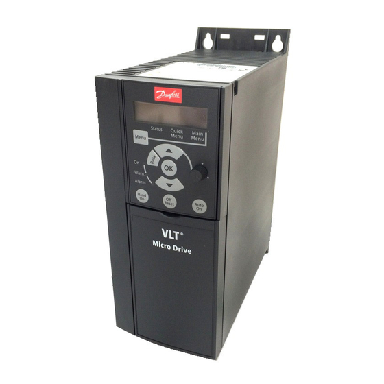
Danfoss VLT FC51 Design Manual (94 pages)
Micro Drive
Brand:
Danfoss
| Category:
DC Drives
| Size: 10 MB
Table of Contents
Table of Contents
3
1 Introduction
7
Available Literature
7
Document and Software Version
7
Abbreviations
7
Definitions
8
Power Factor
10
2 Safety and Conformity
11
Safety
11
Disposal Instruction
12
Approvals
12
CE Labeling
12
Aggressive Environments
13
Vibration and Shock
14
Advantages
14
3 Product Overview
20
Control Structures
20
Control Structure Open Loop
20
Local (Hand On) and Remote (Auto On) Control
20
Control Structure Closed Loop
21
Reference Handling
22
General Aspects of EMC
23
Emission Requirements
24
Galvanic Isolation (PELV)
25
Earth Leakage Current
26
Extreme Running Conditions
26
Motor Thermal Protection
27
4 Selection
28
Options and Accessories
28
Local Control Panel (LCP)
28
Remote Mounting Kit for LCP
28
FC 51 LCP Mounting Instruction
29
FC 51 Remote Mounting Kit Mounting Instruction
29
IP21/TYPE 1 Enclosure Kit
31
Type 1 (NEMA)
31
De-Coupling
31
FC 51 Type 1 Kit Mounting Instruction for M1, M2 and M3
32
FC 51 Type 1 Kit Mounting Instruction for M4 and M5
32
FC 51 IP21 Kit Mounting Instruction
33
FC 51 De-Coupling Plate Mounting Instruction for M1 and M2
34
FC 51 De-Coupling Plate Mounting Instruction for M3
34
FC 51 De-Coupling Plate Mounting Instruction for M4 and M5
35
FC 51 DIN Rail Kit Mounting Instruction
36
Line Filter MCC 107 Installation Instructions
36
Mounting
37
Wiring
37
Dimensions
38
Special Conditions
39
Purpose of Derating
39
Derating for Ambient Temperature
39
Derating for Low Air Pressure
40
Automatic Adaptations to Ensure Performance
40
Derating for Running at Low Speed
40
5 How to Order
41
Drive Configurator
41
FC Identification
41
Type Code
42
Ordering Numbers
43
Options
43
6 How to Install
45
Before Starting
45
Side-By-Side Installation
45
Before Commencing Repair Work
45
Mechanical Dimensions
46
Electrical Installation in General
46
Fuses
47
Mains Connection
48
Motor Connection
48
Use of EMC-Correct Cables
51
Earthing of Screened/Armoured Control Cables
52
Residual Current Device
52
Electrical Overview
53
Power Circuit - Overview
53
Electrical Installation and Control Cables
54
Control Terminals
54
Access to Control Terminals
54
Connecting to Control Terminals
55
Switches
55
Final Set-Up and Test
55
Parallel Connection of Motors
57
Motor Installation
58
Installation of Misc. Connections
58
Safety
59
High Voltage Test
59
Safety Earth Connection
59
7 Programming
60
How to Programme
60
Programming with MCT 10 Set-Up Software
60
Programming with the LCP 11 or LCP
60
Status Menu
61
Quick Menu
61
Quick Menu Parameters
62
Main Menu
65
Quick Transfer of Parameter Settings between Multiple Frequency Converters
65
Read-Out and Programming of Indexed Parameters
65
Initialise the Frequency Converter to Default Settings in Two Ways
66
8 RS-485 Installation and Set-Up
67
Overview
67
Network Connection
67
Frequency Converter Hardware Set-Up
67
EMC Precautions
68
FC Protocol Overview
68
Network Configuration
69
FC Protocol Message Framing Structure
69
Content of a Character (Byte)
69
Telegram Structure
69
Telegram Length (LGE)
69
Frequency Converter Address (ADR)
70
Data Control Byte (BCC)
70
The Data Field
70
The PKE Field
71
Parameter Number (PNU)
71
Index (IND)
71
Parameter Value (PWE)
71
Data Types Supported by the Frequency Converter
72
Conversion
72
Examples
72
Modbus RTU Overview
73
Assumptions
73
What the User Should Already Know
73
Frequency Converter with Modbus RTU
74
Network Configuration
74
Modbus RTU Message Framing Structure
74
Modbus RTU Message Structure
74
Start/Stop Field
75
Address Field
75
Data Field
75
CRC Check Field
75
Coil Register Addressing
75
How to Control the Frequency Converter
77
Function Codes Supported by Modbus RTU
77
Modbus Exception Codes
78
How to Access Parameters
78
Parameter Handling
78
Storage of Data
78
IND (Index)
78
Text Blocks
78
Parameter Values
78
Examples
79
Read Coil Status (01 Hex)
79
Force/Write Single Coil (05 Hex)
79
Force/Write Multiple Coils (0F Hex)
80
Read Holding Registers (03 Hex)
80
Preset Single Register (06 Hex)
80
Preset Multiple Registers (10 Hex)
81
FC Drive Control Profile
81
Control Word According to FC Profile (8-10 Protocol = FC Profile)
81
Status Word According to FC Profile (STW) (8-30 Protocol = FC Profile)
83
Bus Speed Reference Value
84
9 Specifications
85
Index
91
Advertisement
Advertisement
Related Products
Danfoss VLT FC 300
Danfoss VLT FC 360
Danfoss VLT FCM Series
Danfoss VLT FC 300 Series
Danfoss VLT FC 100 LonWorks
Danfoss VLT 2811
Danfoss VLT 2881
Danfoss VLT Automation Drive FC 360
Danfoss VLT 4000
Danfoss VLT N315
Danfoss Categories
Controller
DC Drives
Thermostat
Control Unit
Air Compressor
More Danfoss Manuals
Login
Sign In
OR
Sign in with Facebook
Sign in with Google
Upload manual
Upload from disk
Upload from URL