Sign In
Upload
Manuals
Brands
Daikin Manuals
Air Conditioner
Skyair FHYC140KVE
Daikin Skyair FHYC140KVE Manuals
Manuals and User Guides for Daikin Skyair FHYC140KVE. We have
2
Daikin Skyair FHYC140KVE manuals available for free PDF download: Service Manual
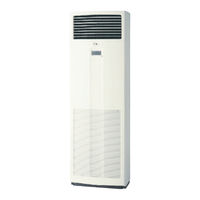
Daikin Skyair FHYC140KVE Service Manual (502 pages)
SkyAir series Service Diagnosis
Brand:
Daikin
| Category:
Air Conditioner
| Size: 2 MB
Table of Contents
Table of Contents
2
1 List of Applicable Models
8
R-FU Series
8
R-GA Series
9
R-G Series
9
R-KU Series
10
R-LU Series
11
2 Symptom-Based Troubleshooting
36
2.1 Overview
36
Applicable Model
38
Supposed Causes
38
2.2 Equipment Does Not Operate
38
Troubleshooting
39
Indoor Unit Fan Operates, but Compressor Does Not Operate
40
Cooling / Heating Operation Starts but Stops Immediately
43
After Unit Shuts Down, It Cannot be Restarted for a While
45
Equipment Operates but Does Not Provide Cooling
48
Equipment Operates but Does Not Provide Heating
51
Equipment Discharges White Mist
54
Equipment Produces Loud Noise or Vibration
56
2.10 Equipment Discharges Dust
59
Remote Controller LCD Displays "88
60
3 Troubleshooting by Remote Controller
61
Procedure of Self-Diagnosis by Remote Controller
61
Wired Remote Controller
62
Hecking an Error or Warning
62
Wireless Remote Controller
63
Taking Corrective Action
63
3.2 Error Codes and Description
66
Outdoor Unit, System
69
Inverter Series
71
3.3 Detailed Error Codes
80
A0 Error of External Protection Device
86
Method of Error Detection
86
Error Decision Conditions
86
A1 Indoor Unit PCB Abnormality
88
A3 Drain Water Level System Abnormality
90
A6 Indoor Unit Fan Motor Abnormality
93
A6 Fan Motor (M1F) Lock, Overload
103
A7 Swing Flap Motor Abnormality / Lock
105
A8 Abnormal Power Supply Voltage
107
A9 Electronic Expansion Valve Coil (Y1E) Abnormality
109
AF Drain System Abnormality
112
AF Drain Level above Limit
114
AJ Capacity Setting Abnormality
115
Remote Controller Display
117
C1 Transmission Error (between Indoor Unit PCB and Fan PCB)
122
C1 Transmission Error (between Indoor Unit PCB and Adaptor PCB)
125
C4, C5, C9 Thermistor Abnormality
128
C6 Defective Combination (between Indoor Unit PCB and Fan PCB)
130
CC Humidity Sensor System Abnormality
132
CJ Remote Controller Thermistor Abnormality
135
E0 Actuation of Safety Device
137
E0 Activation of Outdoor Unit Protection Device
145
E1 Outdoor Unit PCB Abnormality
147
E3 High Pressure System Abnormality
150
E3 Abnormally High Pressure Level (HPS)
155
E3 High Pressure Abnormality (HPS)
157
E3 Actuation of High Pressure Switch
160
E4 Low Pressure System Abnormality
169
E4 Actuation of Pressure Sensor
171
E4 Actuation of Low Pressure Sensor
175
E4 Low Pressure System Abnormality
180
E5 Compressor Motor Lock
183
E6 Compressor Overcurrent
188
Approximate Input Current Value
190
E7 Outdoor Unit Fan Motor Abnormality
191
E9 Electronic Expansion Valve Abnormality
203
E9 Electronic Expansion Valve Coil Abnormality
207
F3 Discharge Pipe Temperature Abnormality
217
F3 Discharge Pipe Temperature Control
225
F6 Abnormal Heat Exchanging Temperature
227
F6 Refrigerant Overcharged
229
H3 High Pressure Switch Abnormality
231
H3 High Pressure Switch System Abnormality
236
H4 Low Pressure Sensor System Abnormality
238
H7 Outdoor Unit Fan Motor Signal Abnormality
242
H9, J3, J5, J6, J7, J8 Thermistor System Abnormality
244
H9 Outdoor Air Thermistor System Abnormality
246
J1 Pressure Sensor Abnormality
248
J2 Current Sensor System Abnormality
250
J3 Discharge Pipe Thermistor System Abnormality
252
J5 Suction Pipe Thermistor Abnormality
255
J6 Heat Exchanger Thermistor System Abnormality
257
J7 Liquid Pipe Thermistor Abnormality
259
J9 Subcooling Heat Exchanger Gas Pipe Thermistor Abnormality
261
JA High Pressure Sensor Abnormality
263
JC Suction Pipe Pressure Sensor Abnormality
266
L1 Outdoor Unit PCB Abnormality
268
L1 Outdoor Inverter PCB Abnormality
270
L1 Outdoor Unit PCB Abnormality
272
L4 Overcurrent of DC Output (Instantaneous)
275
L4 Radiation Fin Temperature Rise
277
Radiation Fin Temperature Detection Value
279
L5 Overcurrent of DC Output (Instantaneous)
285
L5 Momentary Overcurrent of Inverter Compressor
288
L5 Output Overcurrent Detection
291
L5 Inverter Compressor Abnormality
294
L5 Output Overcurrent Detection
297
(L8) Electronic Thermal Switch (Time Lag)
301
L8 Inverter Current Abnormality
304
L8 Inverter Compressor Overcurrent
307
L8 Electronic Thermal (Time Lag)
310
L9 Stall Prevention (Time Lag)
316
L9 Inverter Startup Error
318
LC Transmission Error between Inverter and Control PCB
324
LC Transmission Error (between Control PCB and Inverter PCB)
330
P1 Inverter Over-Ripple Protection
333
P1 Open Phase or Power Supply Voltage Imbalance
336
P4 Radiation Fin Thermistor Abnormality
338
P4 Radiation Fin Thermistor or Related Abnormality
342
PJ Defective Capacity Setting
343
PJ Error in Capacity Setting
345
PJ Field Setting Error after Replacing Main PCB or Defective Combination of PCB
346
PJ Defective Combination of Inverter and Fan Driver
348
PJ Defective Capacity Setting
350
U0 Refrigerant Shortage
354
U0 Low Pressure Drop Due to Refrigerant Shortage or Electronic Expansion Valve Failure
356
U0 Refrigerant Shortage
359
U1 Reverse Phase
365
U2 Insufficient Voltage
368
U2 Power Supply Voltage Abnormality
370
U2 Power Supply Insufficient or Instantaneous Failure
372
U2 Power Supply Voltage Abnormality
377
U3 Check Operation Is Not Executed
380
U4 or UF Transmission Error (between Indoor Unit and Outdoor Unit)
382
U4 Transmission Error between Indoor Unit and Outdoor Unit
388
U5 Transmission Error between Indoor Unit and Remote Controller
411
U7 Transmission Error between Outdoor Units
419
U8 Transmission Error between Main Remote Controller and Sub Remote Controller
422
U9 Transmission Error between Indoor and Outdoor Units in the same System
428
UA Defective Field Setting Switch
431
UA Improper Combination of Indoor and Outdoor Units, Indoor Units and Remote Controller
434
UA Field Setting Switch Abnormality
437
UA Field Setting Switch and Transmission Line Abnormality
440
UC Centralized Address Setting Error
444
UC Address Duplication of Centralized Controller
445
UE Transmission Error between Centralized Controller and Indoor Unit
446
UF Mis-Connection of Field Wiring
454
UF System Is Not Set yet
455
UF Transmission Error between Indoor and Outdoor Unit / Piping and Wiring Mismatch / Refrigerant Shortage
457
Outdoor Units
458
UF Transmission System Abnormality (between Indoor and Outdoor Units)
462
UH System Error, Refrigerant System Address Undefined
463
Check for Fan Motor Connector (Signal Line)
466
3.110 Check
466
Check for Fan Motor Connector (Power Supply Line)
467
Thermistor Resistance / Temperature Characteristics
468
Evaluation of Abnormal High Pressure
471
In Cooling Operation
471
In Heating Operation
472
Evaluation of Abnormal Low Pressure
473
Check for Power Transistor
475
Voltage Measuring Method
477
Pressure Sensor for Except RZQ(S)-B, RZQ-C7 and CMSQ
478
Pressure Sensor for RZQ(S)-B, RZQ-C7 and CMSQ
479
Electronic Expansion Valve Connector and Coil Resistance Criteria
480
Check for Factors Causing Wet Operation
481
Check for Excessive Refrigerant Charging
482
Check for Clogged Points
484
Check for Inadequate Refrigerant
485
Diagnosis of Inadequate Refrigerant
487
Fan Motor Pulse Check
489
Check for Causes of Rise in High Pressure
490
Check for Causes of Drop in Low Pressure
492
Method of Checking Inverter’s Power Transistors and Diode Modules
495
Electronic Circuit
496
Power Module Checking
497
Diode Module Checking
498
Broken Wire Check of the Connecting Wires
499
Warning
501
Advertisement
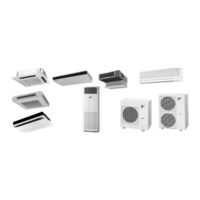
Daikin Skyair FHYC140KVE Service Manual (244 pages)
Cooling Only Heat Pump Split-System Air Conditioner Skyair R(Y)K&F Series Addition of FUY, FVY-L, FAY-FA, FHYC140KVE Models R71, 100KVAL, R125KTAL Models
Brand:
Daikin
| Category:
Air Conditioner
| Size: 9 MB
Table of Contents
Table of Contents
3
Introduction
8
Safety Cautions
8
Cautions Regarding Products after Repair
9
Inspection after Repair
10
Using Icons
11
Using Icons List
11
New Models Functions
13
Cooling Only and Heat Pump
13
Present Model's Functions
15
Cooling Only and Heat Pump
15
Wired Remote Controller
21
Wireless Remote Controller
23
Wireless Remote Controller
25
Method of Field Set (Reset after Maintenance Inspection/Repair)
29
Explanation
29
Field Setting
30
Initial Setting Contents
32
Local Setting Mode no
33
Detailed Explanation of Setting Modes
35
No. of Connected Twin System Indoor Units
35
Air Flow Direction Setting
36
Filter Sign Setting
36
Fan Speed off When Thermostat Is off
38
Centralized Group No. Setting
40
Settings Concerning Maintenance
41
Indoor Unit PCB
41
Outdoor Unit Switches / Setting Jumper
51
Existence of DIP Switch, Jumper and BS
53
Reference Table
53
Emergency Operation
54
Maintenance Mode Setting
55
Function Outline
57
Indoor Unit
57
Fh(Y)C, Fh(Y), Fay, Fuy
57
Outdoor Unit
59
Operation Flowchart (RY71 - 140K)
60
Cooling/Program Dry Operation
60
Heating
62
Electric Function Parts
64
Indoor Unit
64
Outdoor Unit
67
Thermistor Temperature and Resistance Conversion Table
72
Table
72
Function Details
73
Indoor Unit
73
Outdoor Unit
76
Way Valve Control
76
Operation, Stop and Thermostat Control
76
Hps/Lps Detection Function
77
Electronic Expansion Valve Control
77
Abnormally High Discharge Pipe Temperature
77
Freeze Prevention Control
79
Solenoid Valve Control in Cooling Operation
80
Fan Start Control in Heating Operation
81
Maintenance Inspections
88
Optimal Operation Condition
88
How to Handle Request for Maintenance
91
Flow Chart
91
Troubleshooting Based on Equipment Condition
92
Equipment Does Not Operate
93
Fan Operates, but Compressor Does Not
94
Cooling/Heating Operation Starts but Stops Immediately
95
After Equipment Shuts Down, It Cannot be Restarted for a While
96
Equipment Operates but Does Not Provide Cooling
97
Equipment Operates but Does Not Provide Heating
98
Equipment Discharges White Mist
99
Equipment Produces Loud Noise or Shakes
100
Equipment Discharges Dust
101
Remote Controller LCD Displays "88
102
Procedure of Self-Diagnosis by Remote Controller
103
The INSPECTION/TEST Button
103
Self-Diagnosis by Wired Remote Controller
104
Fault Diagnosis by Wireless Remote Controller
105
Remote Controller Display Malfunction Code and Contents
107
Procedure of Self-Diagnosis by LED
108
Troubleshooting by LED on the Indoor Unit's
108
Troubleshooting by LED on the Outdoor Unit's PC Board
108
Troubleshooting by Remote Controller Display / LED Display
109
Explanation for Symbols
109
Malfunction Code and LED Display Table
110
Failure of Indoor Unit PC Board
112
Malfunction of Drain Water Level System (Float Type)
113
Indoor Unit Fan Motor Lock
114
Swing Flap Motor Malfunction / Lock
115
Failure of Capacity Setting
116
Malfunction of Heat Exchange Temperature Sensor System
117
Malfunction of Suction Air Temperature Sensor System
118
Actuation of Safety Device
119
High Pressure System (HPS) Malfunction
120
Low Pressure System (LPS) Malfunction
121
Malfunction of Electronic Expansion Valve
122
Discharge Pipe Temperature Malfunction
123
Malfunction of High Pressure Switch
124
Malfunction of Outdoor Temperature Sensor System
125
Malfunction of Discharge Pipe Temperature Sensor System
126
Malfunction of Heat Exchanger Temperature Sensor System
127
Lack of Gas Malfunction
128
Reverse Phase
129
Malfunction of Transmission (between Indoor and Outdoor Unit)
130
Malfunction of Transmission (between Indoor Unit and Remote Controller)
132
Transmission Error between Main Remote Controller and Sub Remote Controller
133
Failure of Field Setting Switch
134
For FHYC71K
138
Removal of Switch Box Cover
138
Removal of Fan Motor
139
Removal of Suction Grille
140
Removal of Air Filter
141
Removal of Decoration Cover
142
Removal of Decoration Panel
143
Removal of Horizontal Vane
144
Removal of Swing Motor
146
Removal of Switch Box Cover
148
Removal of Fan Motor
149
Removal of Drain Pan
150
Removal of Drain Pump and Drain Hose
151
For FHY71F
153
Removal of Air Filter and Suction Grille
153
Removal of Electrical Parts and PC Boards
154
Removal of Horizontal Blade
156
Removal of Fan Rotor an Motor
157
Removal of Fan Bearing
159
Removal of Bottom Panel and Drain Pan
160
Removal of Swing Motor
163
For FUY71/100/125FJ
164
Removal of Air Filter
164
Removal of Suction Grille
165
Removal of Fan
166
Removal of Fan Motor
168
Removal of Drain Pan
169
Removal of Drain Pump
171
Removal of Swing Motor
172
Removal of Air Flow Control Blade
173
For FAY71F (A)
174
Removal of Air Filter
174
Removal of Slide Panel, Operation Display Cover, and Front Grille
175
Removal of Electrical Parts Box
176
Removal of PC Board
177
Removal of Swing Louvre Unit
178
Removal of Fan Motor
179
Removal of Drain Pan
180
Removal of Heat Exchanger
182
Removal of Fan Rotor
183
For FVY71L~125L
184
Removal of Suction Grille and Air Filter
184
Removal of Electric Parts and Remote Controller
186
Removal of Fan Rotor and Fan Motor
188
Removal of Swing Motor
189
Removal of Heat Exchanger
190
For R(Y)71K
191
Removal of External Casing
191
Removal of Outdoor Unit Fan and Fan Motor
192
Removal of Outdoor Unit PC Board
194
Removal of Electrical Parts Box
195
Removal of Electronic Expansion Valve and Solenoid Valve
197
Removal of 4-Way Valve and Coil
198
Removal of Compressor
199
3Duw#: $Sshqgl
202
Piping Diagrams
203
Wiring Diagram
214
Indoor Unit
214
Outdoor Units (50Hz)
227
Outdoor Units (60Hz)
231
Outdoor Unit (Heat Pump)
234
Advertisement
Related Products
Daikin Skyair FHYC140K
Daikin FHYC140KVE4
Daikin FHYC100FVE
Daikin FH(Y)C125FUVE
Daikin FHYC100B7V1
Daikin Skyair FHYC100K
Daikin Skyair FHYC125K
Daikin FHYC125KVE
Daikin FHYC125BZV1
Daikin FHYC100KVE4
Daikin Categories
Air Conditioner
Heat Pump
Remote Control
Chiller
Air Handlers
More Daikin Manuals
Login
Sign In
OR
Sign in with Facebook
Sign in with Google
Upload manual
Upload from disk
Upload from URL