Sign In
Upload
Manuals
Brands
Bard Manuals
Air Conditioner
MULTI-TECW60AAMB
Bard MULTI-TECW60AAMB Manuals
Manuals and User Guides for Bard MULTI-TECW60AAMB. We have
1
Bard MULTI-TECW60AAMB manual available for free PDF download: Installation Instructions Manual
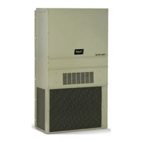
Bard MULTI-TECW60AAMB Installation Instructions Manual (88 pages)
WR Series Wall-Mount Air Conditioner LC6000-100 Controller Free Cooling Unit System
Brand:
Bard
| Category:
Air Conditioner
| Size: 3 MB
Table of Contents
Section 1: Multi-Tec/Lc6000
4
Table of Contents
4
General Information
5
List of Necessary Materials/Tools
8
Site Preparation
9
Model Identification
9
New Shelter Installation Vs. Retrofit Installation
9
Minimum Clearance
9
Clearance to Combustibles
9
Figure 2 Dimensions
10
Wall-Mount Unit Mounting
11
Mounting the Units
11
Figure 3 Outdoor Sensor Installation
11
Figure 4A W18/24 Mounting Instructions
12
Figure 4B W30/36 Mounting Instructions
13
Figure 4C W42/48 Mounting Instructions
14
Figure 4D W60/72 Mounting Instructions
15
Figure 5 Electric Heat Clearance
16
Figure 6 Wall Mounting Instructions
16
Figure 7 Wall Mounting Instructions
17
Figure 8 Common Wall Mounting Installations
18
Wall-Mount Unit Wiring
19
Main Power Wiring
19
Low Voltage Wiring
19
Figure 9 Circuit Routing Label
19
Preliminary Start up
23
Running in Stand Alone (Orphan) Mode
23
Figure 11 Cooling and Heating Setpoints
23
Figure 12 Typical LC6000 Component Location
24
Figure 13 LC6000 Fused Power Supply Terminal
24
LC6000 Controller
25
Mounting the LC Controller
25
Figure 14
26
Installing Remote Indoor Temperature/Humidity Sensor(S)
26
Figure 15
27
Figure 15 Additional Remote Sensor Installation
27
Figure 16
28
Smoke. Hydrogen and Generator Alarms
28
Figure 17
29
Figure 17 Communication Wiring (Daisy Chain)
29
Figure 18 Communication Wiring (Alt. Method)
29
Figure 19
30
Figure 19 Placement of Communication Filters
30
Communication Wiring: Termination at the First Wall-Mount Unit
32
Communication Wiring: Termination at Additional Wall-Mount Units
33
LC6000 Controller Circuit Install
34
Supply Wiring
34
Table 4 LC6000-100 Terminal Block Index
35
Manual 2100-676B
36
Figure 14 Remote Indoor Temperature/Humidity Figure
37
LC6000 Controller Installation
24
System Set up
37
TEC-EYE Hand-Held Diagnostic Tool
37
TEC-EYE Status Screen
38
Setting up Wall-Mount Units for Operation
38
Setting up LC6000 for Operation
39
1 Address each Wall-Mount Unit
38
2 Execute a Run Test on each Unit
38
3 Clear Unit Alarm Logs on each Unit
39
Enable/Disable Zone 1 Indoor Humidity Sensor
40
LC6000 Controller Display and Interface
40
5 Configure Sensors
40
Setting Controller Date and Time
40
Enable/Disable Zone 2 Indoor Humidity Sensor
41
Humidity Sensor
41
Figure 20 Communication Wiring: Termination Figure
42
Clearing LC6000 Alarm Logs
43
Adjusting Sensor Offset Value
44
Table 7 LC6000 Status Messages
45
Manual 2100-676B
46
Manual 2100-676B
47
Section 2: Wr Series/Lc6000
48
Figure 10 WIRING: VAC Supply Wiring
48
Figure 16 Smoke Detector, Hydrogen Detector
48
Manual 2100-676B
48
Manual 2100-676B
49
Free Cooling Unit System
50
Wall-Mount Air Conditioner Units
50
Controller
50
General
50
Manual 2100-676B
50
Shipping Damage
51
Additional Publications
51
Manual 2100-676B
51
General Information
50
List of Necessary Materials/Tools
52
Manual 2100-676B
52
Figure 1
53
Site Preparation
53
Model Identification
53
Manual 2100-676B
53
Minimum Clearance
54
Clearance to Combustibles
54
Manual 2100-676B
54
Manual 2100-676B
55
Wall-Mount Unit Mounting
56
Mounting the Units
56
Manual 2100-676B
56
Figure 3
57
Manual 2100-676B
57
Supply Air Grill Installation
58
Figure 5
58
Manual 2100-676B
58
Manual 2100-676B
59
Manual 2100-676B
60
Manual 2100-676B
61
Wall-Mount Unit Wiring
62
Main Power Wiring
62
Manual 2100-676B
62
Manual 2100-676B
63
Unit Control Voltage Wiring
64
Manual 2100-676B
64
Figure 17
65
Manual 2100-676B
65
Preliminary Start up
66
Running in Stand Alone (Orphan) Mode
66
Figure 18
66
Manual 2100-676B
66
LC6000 Controller Installation
67
Manual 2100-676B
67
LC6000 Controller
68
Figure 20
68
Manual 2100-676B
68
Mounting the LC Controller
68
Figure 21
69
Manual 2100-676B
69
Manual 2100-676B
70
Figure 23
71
Manual 2100-676B
71
Smoke, Hydrogen and Generator Alarms
71
Communication Wiring
72
Figure 24
72
Manual 2100-676B
72
Manual 2100-676B
73
Manual 2100-676B
74
Manual 2100-676B
75
Manual 2100-676B
76
Manual 2100-676B
77
Manual 2100-676B
78
Manual 2100-676B
79
Figure 33
80
Manual 2100-676B
80
Tec-Eye Status Screen
80
TEC-EYE TM Hand-Held Diagnostic Tool
80
Figure 35
81
Setting up Wall-Mount Units for Operation
81
System Set up
80
Manual 2100-676B
81
1 Address each Wall-Mount Unit
81
2 Execute a Run Test on each Unit
82
Executing Run Test
82
Figure 37
82
Run Test Summary
82
Run Test: A/C Circuit
82
Manual 2100-676B
82
Run Test: Motors & Sensors
82
Clearing Unit Alarm Logs
83
Figure 42 Setting Controller Date and Time
83
LC6000 Controller Display/Interface
83
Manual 2100-676B
83
Enable/Disable Zone 1 Indoor Humidity Sensor
84
Enable/Disable Zone 3 Indoor Humidity Sensor
84
Manual 2100-676B
84
Figure
84
Enable/Disable Zone 2 Indoor Humidity Sensor
84
Figure 48
85
Enable/Disable Zone 2 Remote Temperature Sensor
85
Enable/Disable Zone1 Remote Temperature Sensor
85
Manual 2100-676B
85
Enable/Disable Zone 3 Remote Temperature Sensor
86
Figure
86
Manual 2100-676B
86
Figure 53 Adjusting Sensor Offset Value
87
LC6000/TEC-EYE Passwords (Default)
87
Manual 2100-676B
87
Table
87
LC6000 Status Messages
88
Table 6
88
3 Clear Unit Alarm Logs on each Unit
82
Advertisement
Advertisement
Related Products
Bard Mutes
Bard MC4000 SERIES
Bard MV4000 SERIES
Bard MAX-CORE MC1416
Bard MAX-CORE MC1810
Bard MAX-CORE MC1816
Bard MAX-CORE MC1825
Bard MAX-CORE MC2016
Bard MAX-CORE MC2020
Bard MC4002
Bard Categories
Air Conditioner
Heat Pump
Medical Equipment
Furnace
Controller
More Bard Manuals
Login
Sign In
OR
Sign in with Facebook
Sign in with Google
Upload manual
Upload from disk
Upload from URL