Sign In
Upload
Manuals
Brands
Avnet Manuals
Microcontrollers
Xilinx Zynq 7Z045
Avnet Xilinx Zynq 7Z045 Manuals
Manuals and User Guides for Avnet Xilinx Zynq 7Z045. We have
1
Avnet Xilinx Zynq 7Z045 manual available for free PDF download: Manual
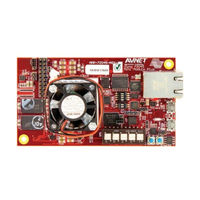
Avnet Xilinx Zynq 7Z045 Manual (36 pages)
Mini-Module Plus
Brand:
Avnet
| Category:
Microcontrollers
| Size: 1 MB
Table of Contents
Table of Contents
5
1 Introduction
8
Description
8
Board Features
8
Reference Designs
8
Ordering Information
9
Figure 1 - Zynq 7Z045 Mini-Module Plus Development Board Picture
9
Table 1 - Ordering Information
9
2 Functional Description
10
Figure 2 - Zynq 7Z045 Mini-Module Plus Development Board Block Diagram
10
Xilinx Zynq 7Z045 AP Soc
11
GTX Interface
11
Table 2 - Zynq 7Z045 AP Soc Features
11
Figure 3 - GTX Clock Sources on the Zynq 7Z045 Mini-Module Plus Development Board
12
GTX Reference Clock Inputs
12
Table 3 - GTX Interface Pin Assignments
12
Figure 4 - PCI Express X4 Interface
13
PCI Express X4 Interface
13
GTX for FMC Expansion Connector, SFP, Display Port and SMA (Baseboard)
14
Table 4 - GTX Pin Assignments for PCI Express
14
Memory
15
DDR3 SDRAM Interface
15
Table 5 - GTX Pin Assignments for Baseboard FMC, SFP, DP and SMA Connectors
15
Figure 5 - DDR3 SDRAM Interface
16
Table 6 - 7Z045 Pin Assignments for DDR3
17
Parallel Flash Interface
18
Figure 6 - Parallel Flash Interface
18
QSPI Flash Interface
19
Table 7 - Parallel Flash Pin Assignments
19
I 2 C EEPROM Interface
20
Micro SD Card Interface
20
Figure 7 - 7Z045 QSPI Flash Interface
20
Table 8 - I C EEPROM Pin Assignments
20
Clock Sources
21
Figure 8 - Clock Nets Connected to Global Clock Inputs
21
CDCM61001 Programmable LVDS Clock Synthesizer
22
Figure 9 - CDCM61001 Clock Synthesizer
22
Table 10 - CDCM61001 Common Application Settings
23
Table 9 - CDCM61001 Clock Synthesizer Pin Description
23
Communication
24
10/100/1000 Ethernet PHY
24
Figure 10 - 10/100/1000 Ethernet Interface
24
Usb Uart
25
USB 2.0 On-The-Go (OTG)
25
Table 11 - Ethernet PHY Pin Assignments
25
Table 12 - USB UART Pin Assignments
25
Real-Time Clock (RTC)
26
Power-On Reset
26
Table 13 - USB 2.0 Pin Assignments
26
Table 14 - RTC Pin Assignments
26
Configuration
27
Configuration Modes and Boot Settings
27
JTAG Interface (PL TAP and ARM DAP)
27
Table 15 - Setting the Configuration Mode "SW5
27
PJTAG Interface (ARM DAP)
28
Figure 11 - JTAG Interface
28
Table 16 - PJTAG Pin Assignments
28
Expansion Connectors
29
Table 17 - JX1 Pin Assignments and Baseboard Signal Mapping
30
Table 18 - JX2 Pin Assignments and Baseboard Signal Mapping
32
2.10 Power
33
Figure 12 - Power Supply Diagram
33
2.11 Thermal Management
34
3 Pre-Programmed Memory
35
QSPI - PCI Express Endpoint
35
Micro SD Card - Linux
35
Appendix A - Assembly Drawing and Jumper Definitions
36
Figure 13 - Board Jumpers
36
Advertisement
Advertisement
Related Products
Avnet MicroZed 7010
Avnet PicoZed 7020
Avnet 78402
Avnet 78370
Avnet 79649
Avnet 78368
Avnet 78404
Avnet 78406
Avnet ADS-XLX-SP3-DEV1500
Avnet ADS-XLX-SP3-DEV2000
Avnet Categories
Motherboard
Control Unit
Single board computers
Computer Hardware
Microcontrollers
More Avnet Manuals
Login
Sign In
OR
Sign in with Facebook
Sign in with Google
Upload manual
Upload from disk
Upload from URL