Sign In
Upload
Manuals
Brands
AUTO GYRO Manuals
Aircrafts
CAVALON
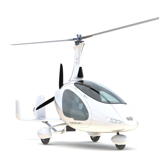
AUTO GYRO CAVALON Autogyro Aircraft Manuals
Manuals and User Guides for AUTO GYRO CAVALON Autogyro Aircraft. We have
3
AUTO GYRO CAVALON Autogyro Aircraft manuals available for free PDF download: Maintenance Manual, Manufacturer Maintenance Manual, Pilot Operating Handbook
AUTO GYRO CAVALON Manufacturer Maintenance Manual (250 pages)
Gyroplane
Brand:
AUTO GYRO
| Category:
Aircrafts
| Size: 9 MB
Table of Contents
Dornierstraße
4
Record of Revisions
5
Revision Service
5
Table of Contents
7
Maintenance Concept and Eligibility
9
Warnings, Caution and Notes
9
ATA100 Numbering System
10
ATA100 – Chapter Code
10
Organization and Handling of the Manual
10
Nomenclature and Structure of Maintenance Tasks (Job Cards)
11
Page Block Code
11
Effectivities
12
Parts List Codes – PC / PIT
12
Abbreviations and Acronyms
13
Service Bulletin (SB) and Airworthiness Directives (AD)
14
MMM-CV-A_16-02-08 Part a - Introduction and Declarations
14
Chapter 00 - Introduction / Aircraft General
17
Chapter 01 - General
18
Definitions, Terms and Standard Procedures
18
Standard Bolt Torques
20
Standard Commercial Tools
20
Conversion Tables
21
Celsius-Fahrenheit Conversion Chart
22
Servicing
22
Chapter 02 - Tools, Spares and Consumable Materials
23
Chapter 03 - Minimum Equipment Requirement
24
Chapter 04 - Manufacturer Life Limitations
25
Liquids and Fluids
26
Chapter 05 - Time Limits, Inspections & Checks
26
Time Limits
26
100 Hrs / Annual Inspection
27
Complementary / Servicing Tasks
27
Daily / Pre-Flight Check
27
Hrs Inspection (One-Time / Non-Recurrent)
27
Temporary Scheduled Inspections & Checks
27
Conditional Inspections
28
Inspections - Special Operational Conditions
28
Operation in Sand or Dust
28
Unscheduled Inspections
28
Winter Operation
28
Birdstrike
29
Inspections - Special Operational Incident
29
Propeller Contact with Obstacle or External Impact
29
Rotor Contact with Obstacle
29
Suspected Hard Landing
29
Functional Test Flight
30
Ground Test Run
30
Lightning Strike
30
Maintenance Records & Aircraft Logs
30
Chapter 06 - Dimensions & Areas
31
Chapter 07 - Lifting / Jacking / Shoring
32
Chapter 08 - Leveling & Weighing
32
Chapter 09 - Towing & Taxiing
32
Chapter 10 - Parking, Storage & Return to Service
32
Chapter 11 - Placards & Markings
33
Chapter 12 - Servicing
35
Cleaning
35
Lubrication: Pre-Rotator Drive Coupling Sleeve
35
Lubrication: Teeter Hinge
35
Servicing: Engine Air Filter
35
Servicing: Tire Pressure
35
Chapter 13-17 - Unassigned / N/A
36
Replenishing/Replacement of Fluids
36
Servicing: Battery
36
Servicing: Engine Coolant
36
Vibration & Noise Analysis
37
MMM-CV-B_14-11-19
38
Interphone / Intercom
41
Speech Communication / Radio
41
Ventilation / Heating
41
DC Electrical Load Distribution
42
DC Generation and Battery
42
Flight Compartment
42
Chapter 21 - Ventilation / Heating
41
Chapter 22 - Unassigned / N/A
41
Chapter 23 - Communications
41
Chapter 24 - Electrical Power
41
Chapter 25 - Equipment / Furnishings
42
Chapter 26 - Fire Protection / Fire Warning
43
Emergency
43
Flight Controls - Rudder
44
Pedals, Control Links and Routing of Cables
44
Chapter 27 - Flight Controls
44
Fuel System ROTAX 912
45
Fuel System ROTAX 914
45
Chapter 28 - Fuel
45
Distribution
45
Storage
45
Chapter 29-30 - N/A
46
Chapter 31 - Indicating System
46
Instruments & Control Panels
46
Panel Layout – Standard / Moving Map Portrait
47
Integrated Display Systems
48
Panel Layout – Glass Cockpit - Single Display
48
Panel Layout – Glass Cockpit - Dual Display
49
Chapter 32 - Landing Gear
50
Chapter 33 - Lights
50
Exterior
50
Main Gear
50
Nose Gear
50
Wheels and Brakes
50
Flight Environment Data
51
Generation / Compressor
51
Chapter 34 - Navigation
51
Chapter 35 - N/A
51
Chapter 36 - Pneumatic
51
Distribution
51
Chapter 37-50 - Unassigned / N/A
52
ATC Transponder
51
Attitude and Direction
51
Chapter 51 - Standard Practices - Structures
52
Chapter 52 - Doors, Covers and Cowlings
52
Chapter 53 - Fuselage
52
Chapter 54 - N/A
52
Emergency Exit
52
Passenger / Crew
52
Service Covers and Cowlings
52
Standard Practices - Structures
52
56-10-00 Flight Compartment / Canopy
53
56-15-00 Canopy Windows
53
Chapter 57-60 - Unassigned / N/A
53
Chapter 55 - Stabilizers
53
Chapter 56 - Windows
53
Part C - System Description Section (Ch. 21 - 90)
53
Rudder
53
Controlling
54
Rotor – Teetering Parts
54
Chapter 61 - Propeller
54
Chapter 62 - Rotor
54
Propeller Assembly
54
Chapter 63 - Rotor Drive
55
Pre-Rotator
55
Rotor Gimbal Head
55
Rotor Head Bridge, Bearing and Teeter Tower
55
Rotor RPM Monitoring
55
Rotor Vibration Isolation
55
Chapter 64-66 - N/A
56
Chapter 67 - Rotor Flight Control
56
Pitch Trim System / Rotor Brake
56
Pre-Rotator Drive
56
Pre-Rotator Lower Engagement
56
Chapter 68-70 - Unassigned / N/A
57
Chapter 71 - Power Plant
57
Engine Air Intakes
57
Engine Cowling
57
Engine Drains
57
Engine Electrical Harness
57
Engine Firewalls
57
Engine Mounts
57
Roll Trim System
57
Chapter 72 To 74 - Engine Related
58
Chapter 75 - Air / Engine Cooling
58
Chapter 76 - Engine Controls
59
Chapter 77 - Engine Indicating
59
Engine Shutdown / Emergency
59
Power Control / Choke
59
Temperature
59
Chapter 78 - Exhaust
60
Chapter 79 - Oil System
60
Distribution and Cooling
60
Indicating
60
Integrated Engine Instrument Systems
60
Oil Cooler
60
Oil Hoses and Lines
60
Storage / Oil Tank
60
Wiring Diagram - Aircraft Main Wiring Harness
63
Wiring Diagram – Aircraft Main Wiring Harness
64
Wiring Diagram - Cockpit RH
65
Wiring Diagram – Cockpit RH
66
Wiring Diagram - Optional Comfort Features Seats
67
Wiring Diagram – Optional Comfort Features Seats
68
Wiring Diagram - Flight Control Sticks
69
Wiring Diagram – Flight Control Sticks
70
Wiring Diagram - Landing Lights
71
Wiring Diagram – Landing Lights
72
Wiring Diagram - NAV / Strobe Lights
73
Wiring Diagram – NAV / Strobe Lights
74
Wiring Diagram - Cockpit LH (Standard)
75
Wiring Diagram – Cockpit LH (Standard)
76
Wiring Diagram - Main Fuse / Battery
77
Wiring Diagram – Main Fuse / Battery
78
Wiring Diagram - Cockpit Centre
79
Wiring Diagram – Cockpit Centre
80
Wiring Diagram - Cockpit (General)
81
Wiring Diagram – Cockpit (General)
82
Wiring Diagram - Pneumatic System (Standard / Comfort)
83
Wiring Diagram – Pneumatic System (Standard / Comfort)
84
Wiring Diagram - Fuel Pumps
85
Wiring Diagram – Fuel Pumps
86
Wiring Diagram - Fuel Level and Low Level Sensors
87
Wiring Diagram – Fuel Level and Low Level Sensors
88
Wiring Diagram - Engine Wiring Harness
89
Wiring Diagram – Engine Wiring Harness
90
Wiring Diagram - Engine Turbo Control Unit (TCU) Wiring Harness
91
Wiring Diagram – Engine Turbo Control Unit (TCU) Wiring Harness
92
Pneumatic Scheme - Standard
93
Pneumatic Scheme - Standard
94
Pneumatic Scheme - Comfort
95
Pneumatic Scheme - Comfort
96
Retrofit: End Position Detection IVO Propeller
97
MMM-CV-D_15-01-09 Part D - Diagrams and Charts
97
Retrofit: End Position Detection IVO Propeller
98
Lifting Belt Looped Around Teeter Bolt
101
Lifting of the Gyroplane
101
Precautions and Safety Measures
101
Jacking of the Gyroplane
103
Precautions and Safety Measures
103
Special Tools and Consumable Materials
103
Unload Main Gear
103
Unload Nose Gear
103
Shoring of the Gyroplane
105
Shoring, Road Transport or Container Transport
105
Illustrations
106
Lash-Down Methods of Gyroplane
106
Leveling of the Gyroplane
107
Measurement of Stabilizer Alignment
107
Installation Position Battery
109
Removal-Installation: Battery
109
Cable Connector on Rectifier-Regulator and Fuse Carrier
112
Modified Fuse Carrier
112
Attachment of the Relay
113
Fuel Pumps P1 / P2 and Cable Connector of Fuel Pump Wiring Harness
113
Secured Capacitor
113
Description: Emergency Locator Transmitter
115
Installation Position ELT
115
Description: Fire Indicating System
117
Indication Logic
118
Installation - Seen from Behind
118
Installation - Seen from LH Side
118
Installation - Seen from RH Side
118
Check-Adjustment: Roll Control Travel Limitation
119
Check-Adjustment: Rudder Control Angles
121
Rudder Control Angle Setting
122
Measurement Procedure
123
Inspection: Fuel Filter
125
Replacement: Fuel Filter
127
Fuel Pumps and Filters (Detail)
128
Replacement: Electrical Fuel Pumps
129
El. Fuel Pump Terminal (Detail)
130
Replacement: Main Gear Suspension Bow Attachment Bolts
131
10 MM Drill Bit Equipped with Washers
132
Drilling to a Diameter of 10 MM
132
Main Gear Suspension Bow
132
Main Gear Suspension Bow Cover and Service Cover
132
Replacement: Nose Gear Rubber Damper
133
Nose Gear Assembly
134
Removal-Installation: Wheels
135
Nose Wheel
137
Main Wheel
138
Replacement: Main Wheel Brake Pads
139
Main Wheel with Brake
140
Replacement: Wheel Bearing
141
Main Wheel and Bearing
142
Test: Pitot Static System Integrity
143
Pitot Static Instruments Connecting Diagram
144
Pitot Static Integrity Test Equipment
144
Cleaning: Pitot Static System
145
Static Ports (2 X ) and Pitot Port
145
Filter/Dryer
147
Rear Wall (Installation Wall)
147
Replacement: Filter/Dryer
147
Lower Engine Cowling - Removal
149
Removal-Installation: Cowlings
149
Upper Engine Cowling - Installation
149
Upper Engine Cowling - Removal
149
Cowling and Mast Cover
150
Description: Service Covers in Cockpit Shell
151
Rear Wall 'Installation Wall' (Fire Wall Removed)
152
Service Cover for Control Linkage (LH) and below Seat (RH)
152
Service Covers below Seats ('Equipment Cover')
152
Installation Position of Keel Tube Protection Pad
153
Replacement: Keel Tube Protection Pad
153
Repair: Cracks in Acrylic Glass
155
Channel on Material Bottom Side
156
Filled Channel on Material Top Side
156
Filled Channels on Material Top and Bottom Side
156
Milling of a Channel on Material Top Side
156
Removal-Installation: Propeller - Htc
157
Propeller HTC
158
Disassembly-Assembly: Propeller - Htc
159
Adjustment: Propeller Pitch - Htc
161
Propeller Pitch Adjustment and Tool
162
Detail Blade
163
Detail Hub
163
Contents of the Kit
166
Pin Assignment of Wiring Harness
166
Rocker Switch and Leds
166
Rocker Switch and Leds - Seen from Behind
166
Trouble-Shooting: Ivo-Variable Pitch Propeller
167
Fault Tree IVO Variable Pitch Propeller
168
Removal: Rotor - Teetering Parts
169
WARNING: Object Is Heavy! Inadequate Handling Could Cause Injury. Use Proper Lifting Techniques or Assistance
169
Removal Rotor - Teetering Parts (Effectivity: RS II)
170
Disassembly: Rotor - Teetering Parts
171
Disassembly Rotor - Teetering Parts (Effectivity: RS II)
172
Assembly: Rotor - Teetering Parts
173
Installation: Rotor - Teetering Parts
175
Installation Rotor - Teetering Parts (Effectivity: RS II)
176
Check-Adjustment: Rotor System Alignment
177
Positioning of Measuring Cord
178
Reference Point at Grease Nipple
178
Rotor System Placed on Stands
178
Inspection: Rotor - Teetering Parts
179
Teeter Bushings, Block and Tower - Cross Section View
180
Inspection: Rotor Blades
181
Critical Blade Area
182
Measurement of Blade Root Linearity
182
Inspection: Rotor Hub Bolts
183
Rotor Hub
184
Replacement: Teeter Bushings
185
Teeter Bushings, Block and Tower - Exploded View
187
Replacement: Drive Gear
189
Rotor System Must be Removed, See 62-11-00
189
Rotor Head
191
Split Pin and Castle Nut
191
Allen Wrench between Rotor Head and Main Bolt
192
Check-Adjustment: Rotor Head Main Bolt Axis
193
Adjustment of Rotor Head Main Bolt Axis
194
Inspection: Rotor Head Bridge, Bearing and Teeter Tower
195
Check-Adjustment: Rotor Control Friction
197
Gimbal Head Assembly, Rotor System II (with Spring Washers)
198
Measurement of Rotor Control Friction
198
Inspection: Rotor Gimbal Head
199
Arrangement of Spring Washers on Gimbal Head - Version II
200
Rotor Gimbal Head - Version II
200
Removal-Installation: Top Mast
201
WARNING: When Working with Cranes or Other Lifting Equipment the General Safety Regulations Have to be Respected at All Times
201
Pneumatic Connection Bendix
203
Pneumatic Hoses
203
Roll Control
203
Temperature Sensor
203
Installation of Mast Bushes
204
Push-Pull Control Cable Bulkhead Attachment
204
Top Mast
204
Inspection: Mast Mounting Bushings
205
Force Applied against Flight Direction
206
Force Applied in Flight Direction
206
Fuselage Reference Point
206
Mast Reference Point
206
Replacement: Mast Mounting Bushings
207
Bottom Mast with Mast Mounting Bushings
208
Removal-Installation: Pre-Rotator Clutch
209
Check-Adjustment: Pre_Rotator Clutch
211
Connection between Clutch and Pressure Reducer
212
Connection of Check Valve to Pressure Reducer
212
Thread Pin M8X50
212
Upper Pre-Rotator Drive Connected to Bendix Shaft
212
Inspection: Pre-Rotator Clutch
213
Replacement: Pre-Rotator Clutch Lining
215
Loctite 648 on Inner and Outer Thread
216
M8X20 Screw Plug
216
Pneumatic Clutch III
216
Replacement: Pre-Rotator Clutch Dog Gear
217
Inspection: Pre-Rotator Upper Engagement
219
Replacement: Pre-Rotator Upper Bearings
221
Prerotator Upper Bearing
222
Repair: Pre-Rotator Upper Engagement
223
Replacement: Rotor Brake Pad
225
Rotor Bridge with Brake Pad
226
Inspection: Flight Control Push-Pull Cables
227
Measurement of Freeplay
228
Modification of Rotor Head Stop
228
Pitch and Roll - Upper Attachment
228
Retrofit: Ppc Clamps
229
PPC Clamps
230
Replacement: Pitch Trim/Brake Pneumatic Seal
231
Removal-Installation: Centre Console
233
Centre Console
234
Inspection: Clearance Engine Installation (R914)
235
Fire Wall - Removable Part(S)
237
Removal-Installation: Fire Wall
237
Removal-Installation:radiator
239
Modification: Reconfigure Fan Reverse
241
Fan Reverse Cable - Detached
242
Fan Reverse Cable - Modified
242
Fan Reverse Cable - Secured
242
Fan Reverse Control Unit
242
Replacement: Wool of Muffler Tube
243
Drill out the Rivet Pin
245
Hose Clamps
245
Rivets at the Hot and Hinge Pin Clamp
245
Installation of Absorption Wool
246
Riveting of the Outer Shell
246
Rivets at the Cold End of Muffler Tube
246
Installation of Hose Clamps and Hinge Pin Clamp
247
Installation of Locking Wire
247
Position of the Muffler Tube
247
Advertisement
AUTO GYRO CAVALON Maintenance Manual (293 pages)
Brand:
AUTO GYRO
| Category:
Aircrafts
| Size: 7 MB
Table of Contents
Table of Contents
3
Preface
4
Introduction
5
Revision Service
5
Record of Revisions
6
Maintenance Concept and Eligibility
8
Warnings, Cautions and Notes
9
Organization and Handling of the Manual
10
ATA100 Numbering System
10
ATA100 Chapter Code
10
Nomenclature and Structure of Maintenance Tasks (Job Cards)
11
Page Block Code
11
Effectivities
12
Abbreviations and Acronyms
13
Chapter 00 Introduction / Aircraft General
18
Chapter 01 General
19
Definitions, Terms and Standard Procedures
19
Standard Bolt Torques
21
Standard Commercial Tools
21
Conversion Tables
22
Tools, Spares and Consumable Materials
24
Consumable Materials
24
Chapter 03 Minimum Equipment Requirement
25
Chapter 04 Manufacturer Life Limitations
26
Chapter 05 Time Limits, Inspections & Checks
28
Time Limits
28
Scheduled Inspections & Checks
29
Daily / Pre-Flight Check
29
Complementary / Servicing Tasks
29
Hrs Inspection (One-Time / Non-Recurrent)
29
Hrs / Annual Inspection
29
Temporary Scheduled Inspections & Checks
29
Unscheduled Inspections
30
Conditional Inspections
30
Inspections - Special Operational Conditions
30
Operation in Sand or Dust
30
Winter Operation
30
Inspections - Special Operational Incident
31
Suspected Hard Landing
31
Rotor Contact with Obstacle
31
Propeller Contact with Obstacle or External Impact
31
Birdstrike
31
Lightning Strike
32
Ground Test Run
32
Functional Test Flight
32
Maintenance Records & Aircraft Logs
32
Chapter 06 Dimensions & Areas
33
Chapter 07 Lifting / Jacking / Shoring
34
Chapter 08 Leveling & Weighing
34
Chapter 09 Towing & Taxiing
34
Chapter 10 Parking, Storage & Return to Service
34
Chapter 11 Placards & Markings
35
Servicing
36
Cleaning
36
Lubrication
36
Lubrication: Teeter Hinge
36
Lubrication: Pre-Rotator Drive Coupling Sleeve
36
Servicing: Engine Air Filter
36
Servicing: Tire Pressure
36
Servicing: Battery
37
Servicing: Engine Coolant
37
Replenishing/Replacement of Fluids
37
Chapter 13 Unassigned / N/A
38
Chapter 14 Unassigned / N/A
40
Autopilot
45
System / Equipment Descriptions
45
GMC 507 Autopilot Mode Controller
45
GSA 28 Servo
45
Audio Output
45
GFC 500 Interface Summary
46
Power Requirements
46
Control and Operation
46
Gmc 507
46
Autopilot Disconnect/Trim Interrupt Switch
47
Trim Switch
47
Go Around (GA) Switch
47
Electrical Bonding (Advisory Material)
47
Consideration for Untreated or Bare Dissimilar Metals
48
Preparation of Aluminium Surfaces
49
Troubleshooting
50
General GFC 500 Troubleshooting
50
GFC 500 Will Not Engage
50
GFC 500 Will Not Pass Pre-Flight Test (PFT)
51
GFC 500 CAN Bus Errors
52
GFC 500 Interconnect Drawings
52
Connector Layout
52
Maintenance Intervals
52
Servicing Information
53
On Condition Servicing
53
Required Tools
53
Special Tools
53
Equipment Removal & Installation
53
Gmc
54
GSA 28 Servos
54
Autopilot Components Installation
55
Overview
55
Yaw Components
56
Roll Components
58
Pitch Components
59
Cable Installation
60
Additional Power Cable Installation
61
Autopilot Disconnect Button and Pre-Rotator Button Change
62
Pre-Rotator Button
62
Autopilot Disconnect Button
62
Pneumatic System
63
Electrical Bonding Test
63
Requirements
63
Test Equipment
64
Electrical Bonding Procedure
64
Disconnect Tone and Sonalert Test
64
Pitch and Roll Clamp Check
65
Visual Inspection
67
GFC 500 LRU Replacement/Configuration & Testing
68
Gmc
68
GSA 28 Servo
68
GFC 500 Software Load and Configuration Procedures
68
GMC 507 and GSA 28 Software Loading
68
GFC 500 System Configuration
69
GFC 500 Return to Service Procedure
69
Yaw Offset and Pitch/Roll Offset Calibration
69
G5 Systems
69
G3X Systems
70
Pre-Flight Test (PFT)
70
Normal Mode Tests
70
Servo Tests
71
Roll Servo Functional Check
71
Pitch Servo Functional Check
71
Yaw Damper Functional Check
71
GFC 500 Functional Checks
71
Autopilot Switch Checks
72
Interface Checks
72
VOR Mode Check
72
GPS Mode Check
73
IAS Mode Check
73
VS Mode Check
74
ALT Mode Check
74
ALTS Mode Check
75
LVL Mode Check
75
22-08- Appendix A: Installation Specific Information
76
22-08-A1 General Master Installation List
76
22-08-A2 Configuration Log (for G5 Equipped Aircraft)
77
22-08-A3 Configuration Log (for G3X Equipped Aircraft)
79
Communications
82
Speech Communication / Radio
82
Interphone / Intercom
82
Electrical Power
82
DC Generation and Battery
83
DC Electrical Load Distribution
83
Equipment / Furnishings
84
Flight Compartment
84
Emergency
85
Fire Protection / Fire Warning
86
Flight Controls
87
Flight Controls - Rudder
87
Chapter28 Fuel
88
Storage
88
Distribution
88
Indicating
89
Indicating System
90
Instruments & Control Panels
90
Right Panel II
92
Integrated Display Systems
92
Landing Gear
95
Main Gear
95
Nose Gear
95
Wheels and Brakes
95
Lights
95
Exterior
95
Navigation
96
Flight Environment Data
96
Attitude and Direction
96
ATC Transponder
96
Pneumatic
96
Generation / Compressor
96
Distribution
96
Unassigned / N/A
97
Standard Practices - Structures
97
Doors, Covers and Cowlings
97
Passenger / Crew
97
Emergency Exit
97
Service Covers and Cowlings
97
Fuselage
97
Stabilizers
99
Rudder
99
Windows
99
Flight Compartment / Canopy
99
Canopy Windows
99
Unassigned / N/A
100
Propeller
100
Propeller Assembly
100
Controlling
100
Rotor
101
Rotor - Teetering Parts
101
Rotor Head Bridge, Bearing and Teeter Tower
102
Rotor Gimbal Head
102
Rotor RPM Monitoring
102
Rotor Vibration Isolation
102
Rotor Drive
102
Pre-Rotator
102
Pre-Rotator Lower Engagement
102
Pre-Rotator Drive
102
Pre-Rotator Upper Engagement
103
Rotor Brake System
103
Rotor Flight Control
103
Pitch Trim System / Rotor Brake
103
Roll Trim System
103
Unassigned / N/A
104
Power Plant
104
Engine Cowling
104
Engine Mounts
104
Engine Firewalls
104
Engine Electrical Harness
104
Engine Air Intakes
104
Engine Drains
104
Air / Engine Cooling
105
Engine Controls
106
Power Control / Choke
106
Engine Shutdown / Emergency
106
Chapter77
106
Engine Indicating
106
Power
106
Temperature
107
Integrated Engine Instrument Systems
107
Exhaust
107
Oil SYSTEM
107
Storage / Oil Tank
107
Distribution and Cooling
107
Oil Hoses and Lines
107
Oil Cooler
107
Indicating
107
Wiring Diagram - Aircraft Main Wiring Harness
109
Wiring Diagram - Cockpit RH (Standard)
111
Wiring Diagram - Cockpit RH (EFIS)
113
Wiring Diagram - Cockpit RH (Upgrade Interior Heater II)
115
Wiring Diagram - Optional Comfort Features Seats
117
Wiring Diagram - Flight Control Sticks
119
Wiring Diagram - Flight Control Sticks with Autopilot
121
Wiring Diagram - Landing Lights
123
Wiring Diagram - NAV / Strobe Lights
125
Wiring Diagram - Cockpit LH (Standard)
127
Wiring Diagram - Starter / Battery
129
Wiring Diagram - Cockpit Center
131
Wiring Diagram - Cockpit (General)
133
Wiring Diagram - Pneumatic System (Standard / Comfort)
135
Wiring Diagram - Pneumatic System (Autopilot)
137
Wiring Diagram - Fan
139
Wiring Diagram - Fuel Level and Low Level Sensors
141
Wiring Diagram - Engine Wiring Harness
143
Wiring Diagram - CAN Convertor
145
Wiring Diagram - 24V Option
147
Wiring Diagram - Cockpit Left Dimmer
149
Wiring Diagram - Dimmer
151
Wiring Diagram - Camera Mount
153
Wiring Diagram - Garmin G3X Cockpit 2 X 7
155
Wiring Diagram - Garmin G3X Cockpit 1 X 10
157
Wiring Diagram - G3X Installation Kit
159
Wiring Diagram - G3X Installation
161
Wiring Diagram - GTX 35R Installation
163
Wiring Diagram - GTR 20 Installation
167
Wiring Diagram - GMA 245 Installation
171
Wiring Diagram - GMA 245 to ATR833 Adaptor
175
Wiring Diagram - GDL 50 Installation
179
Wiring Diagram - GDL 50 Data / Power Cable
181
Wiring Diagram - GMC507 Installation
183
Pneumatic Scheme - Standard/Comfort
185
Pneumatic Scheme - Autopilot
187
General, References and Requirements
192
Task May Only be Performed by an Organization or Individual Trained and Entitled to Carry out 'Professional Maintenance
192
Secure Gyroplane against Unauthorized or Unintended Operation
192
Special Tools and Consumable Materials
192
Precautions and Safety Measures
192
Rotor System Must be Removed, See
193
WARNING: Object Is Heavy! Inadequate Handling Could Cause Injury. Use Proper Lifting Techniques or Assistance
271
WARNING: When Working with Cranes or Other Lifting Equipment the General Safety Regulations Have to be Respected at All Times
271
AUTO GYRO CAVALON Pilot Operating Handbook (147 pages)
Brand:
AUTO GYRO
| Category:
Aircrafts
| Size: 4 MB
Table of Contents
Table of Contents
5
Intentionally Left Blank
11
General
13
Introduction
13
Certification
13
Performance Data and Operating Procedures
13
Section 1 - General
13
Definition of Terms
15
Important Note
15
Three-View of the Cavalon
16
Description
17
Technical Data
17
Rotor
17
Engine
18
Propeller
18
In-Flight Adjustment
18
Unit Conversion
19
Abbreviations and Terminology
20
Table of Contents
23
Limitations
25
General
25
Section 2 - Limitations
25
Environmental Limitations
27
Colour Code for Instrument Markings
27
Airspeed Limitations and Instrument Markings
28
Rotor Speed Limitations and Instrument Markings
28
Powerplant Limitations and Instrument Markings
29
Weight and Balance
31
Weight Limits
31
Centre of Gravity (CG) Limits
31
Flight Crew
32
Kinds of Operation
32
Demonstrated Structural Load Factors
32
Fuel
33
Minimum Equipment
33
Approved Fuel Grades
33
Fuel Tank Capacities
33
Unusable Fuel
33
Placards
34
Table of Contents
39
Emergency Procedures
41
Engine Failure
41
Section 3 - Emergency Procedures
41
Air Restart Procedure
42
Landing into Trees or High Vegetation
42
Degradation of Engine Power
42
Evacuating the Aircraft
43
Smoke and Fire
43
Off-Field Landing
43
Flight Control Malfunction
44
Engine Power Control / Throttle
44
Rudder Malfunction
44
Rotor Head Control
44
Pitch Oscillation Recovery
45
Vibration
45
Trim Runaway
45
Door Open in Flight
47
Warning and Caution Lights
48
GEN or Low Volt Indicator Light
48
Low Volt
48
BOOST WARN Light 'Boost' (Red) - Only ROTAX 914 UL
49
BOOST CAUTION Light 'Caution' (Orange) - Only ROTAX 914 UL
49
Fire
49
Parameters out of Limits
50
Rotor Bearing Temperature
50
Low Fuel (if Installed)
50
Deleted
50
Fan
50
Loss of Visibility
51
Not Used)
51
Rotor Icing
51
Landing with a Deflated Tyre
51
Not Used
52
Alternative Method of Engine Shut-Down
52
Table of Contents
55
Normal Procedures
57
Airspeeds for Safe Operation
57
Preparation for Flight
57
Daily or Pre-Flight Checks
57
Section 4 - Normal Procedures
57
Before Boarding
60
Before Starting Engine
61
Starting Engine
62
Taxi and Run-Up
63
Take-Off Procedure
63
Take-Off Run
65
Climb
65
Cruise
65
Descent
65
Approach
66
Landing
66
Go-Around
67
After Landing
67
Engine Shut-Down
68
Parking
68
Special Procedure: Short Field Take-Off
68
Special Procedure: Slow Speed Sink and Recovery
68
Flight with Doors Removed
69
Training Engine In-Flight Shut-Down and Air Restart
70
Noise Abatement
70
Table of Contents
73
Performance
75
Demonstrated Operating Temperature
75
Airspeed Correction
75
Section 5 - Performance
75
Height-Velocity Diagram
76
Speeds
77
Rate of Climb
77
Take-Off and Landing Data
77
Influence on Take-Off Distance and Climb Rate
78
Sink Rate and Glide Ratio
80
Additional Performance Data
80
Sound Exposure Level / Noise Characteristics
80
Fuel Flow
80
Service Ceiling
80
Weight and Balance
85
General
85
Weight and Balance Record
85
Compliance with Weight and Balance
85
Intentionally Left Blank
87
System Description
89
Introduction
89
Airframe and Undercarriage
89
Doors, Windows and Exits
89
Fuel System
89
Section 7 - System Description
89
Pneumatic System
91
Power Plant
92
Propeller
92
Rotor System
92
Vibration Damping
93
Flight Controls
93
Electrical System
96
Lighting System
97
Electrical Circuit Protection
97
Avionics
99
Instrument Panel
100
Intercom
102
Pitot Static
102
Indicators and Sensors
102
Seats and Seatbelts
102
Stowage Capacity
102
Table of Contents
103
Handling and Servicing
105
Maintenance Obligations
105
General
105
Ground Handling
106
Cleaning
106
Refuelling
107
Checking of Engine Oil Level
107
Checking of Engine Coolant Level
108
Tyre Pressure
108
Lubrication and Greasing
109
Replenishing of Fluids
109
Engine Air Filter
109
Propeller
109
Engine Oil
109
Battery
110
Winter Operation
110
Removal, Disassembly, Assembly and Installation of the Rotor
110
Removal of the Rotor System
111
Disassembly of the Rotor System
112
Assembly of the Rotor System
112
Installation of the Rotor System
113
Road Transport
114
Repairs
114
Pilot Maintenance
115
Supplements
117
IVO-Prop In-Flight Adjustable Variable Pitch Propeller
119
Lights
127
9-2.1 General
127
9-2.2 Limitations
127
9-2.3 Emergency Procedures
127
9-2.4 Normal Procedures
127
9-2.5 Performance
127
9-2.6 Weight and Balance
127
9-2.7 System Description
127
9-2.8 Handling and Servicing
127
Gps/Moving Map Systems
129
9-3.1 General
129
9-3.2 through 9-3.6
129
9-3.7 System Description
129
9-3.8 Handling and Servicing
129
Fire Indication
131
9-4.1 General
131
9-4.2 Limitations
131
9-4.3 Emergency Procedures
131
9-4.4 through 9-4.9
131
Not Used
133
Table of Contents
135
Safety Tips
137
Low-G Avoidance
137
Side Slip in Gyroplanes
137
Flying Low on Fuel Is Dangerous
138
Do Not Push the Envelope and Remain Easy on the Controls
138
Strobe Lights on - for Your Own and Other's Safety
138
Propellers and Rotors Can be Extremely Dangerous
138
Power Lines and Cables Are Deadly
138
Loss of Visibility Can be Fatal
138
Overconfidence Prevails in Accidents
139
Flying Low over Water Is very Hazardous
139
Conversion Pilots Constitute High Risk When Flying Gyroplanes
139
Beware of Demonstration or Initial Training Flights
140
Training Off-Field Simulated Engine Failures
140
Appendix
141
Operator Registration Form
141
Incident Reporting Form
141
Advertisement
Advertisement
Related Products
AUTO GYRO Cavalon Pro
AUTO GYRO CALIDUS 915is
AUTO GYRO CALIDUS 916iS
AUTO GYRO Rotax 916 IS
AUTO GYRO Categories
Aircrafts
Toy
More AUTO GYRO Manuals
Login
Sign In
OR
Sign in with Facebook
Sign in with Google
Upload manual
Upload from disk
Upload from URL