Sign In
Upload
Manuals
Brands
Addi-Data Manuals
PCI Card
APCI-1710
Addi-Data APCI-1710 Manuals
Manuals and User Guides for Addi-Data APCI-1710. We have
4
Addi-Data APCI-1710 manuals available for free PDF download: Technical Description, Function Description, Manual
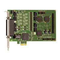
Addi-Data APCI-1710 Technical Description (84 pages)
Multifunction counter board, optically isolated
Brand:
Addi-Data
| Category:
Computer Hardware
| Size: 1 MB
Table of Contents
Table of Contents
5
Definition of Application
10
Intended Use
10
Usage Restrictions
10
General Description of the Board
10
User
12
Qualification
12
Personal Protection
12
Handling of the Board
13
Fig. 3-1: Correct Handling
13
Technical Data
14
Electromagnetic Compatibility (EMC)
14
Physical Set-Up of the Board
14
Versions
15
Limit Values
15
Inputs
16
Outputs
17
Fig. 4-1: Output Current Versus Differential Output Voltage
17
Safety
19
Component Scheme
20
Available Functions of the Apci-1710
21
Available Signals
21
Connectable Signal Lines
21
Maximal Signal Wirings of the APCI-1710
21
Table 5-1: Maximal Input Lines on the Board
21
Table 5-2: Maximal Input Lines on a Module
21
Table 5-3: Maximal Output Lines on the Board
21
Available Functions
22
Programmable Functions of the Counter Board
22
Table 5-4: Maximal Output Lines on a Module
22
Table 5-5: Possible Applications of the Counter Board
22
Connection Facilities Depending on the Chosen Function
23
Delivered Manuals
23
Table 5-6: Maximal Application Functions on the Board
23
Installation of the Board
24
Opening the PC
24
Selecting a Free Slot
24
Fig. 6-1: PCI-5V Slot (32-Bit)
24
Plugging the Board into the Slot
25
Closing the PC
25
Fig. 6-2: Inserting the Board
25
Fig. 6-3: Fastening the Board at the Back Cover
25
Software
26
Delivered Software
26
Configuration of the APCI-1710 with ADDIREG
26
Fig. 7-1: Registration Program ADDIREG
27
Fig. 7-2: Configuration of a New Board
29
Fig. 7-3: PCI Boards
30
Registration of a New Board
31
Changing the Registration of an Existing Board
31
Loading a Function into a Function Module
32
Module Configuration with SET1710
33
Fig.7-4: SET1710: Configuration Program for Modules
33
Fig. 7-5: Selection of a APCI-/CPCI-170
33
Fig. 7-6: General Information
34
Fig. 7-7: Function List and Module Configuration
34
Setting a Module Configuration
35
Fig. 7-8: Setting a Module Configuration by Mouse Click
35
ADDI-DATA on the Internet
36
Fig. 7-9: Setting a Module Configuration by Keyboard
36
Connecting the Peripheral
37
Connector Pin Assignment
37
50-Pin SUB-D Front Connector ST1
37
Fig. 8-1: 50-Pin SUB-D Male Connector (ST1)
37
Supply for 24 V Digital Outputs (Channel H)
40
Fig. 8-2: Terminal ST2
40
50-Pin Ribbon Cable Connector ST5
41
Fig. 8-3: Position of the Connector ST5 on the Board
41
Fig. 8-4: Pin Assignment of the Ribbon Cable Connector
41
Connection of Mass-Related Inputs and Outputs
43
Fig. 8-5: Connection of a Mass-Related Input
43
Connection of the Differential Digital I/O
44
Fig. 8-6: Connection of a Mass-Related Output
44
Fig. 8-7: Connection of a Differential Input
44
Fig. 8-8: Example: Connection of 2 Incremental Encoders at FM1
45
Fig. 8-9: Connection of a Differential Output
45
Connection at the TTL Inputs and Outputs
46
Fig.8-10: Connection at TTL Inputs and Outputs
46
Functions of the Board
47
Description
47
Fig. 9-1: Block Diagram of the APCI-1710
47
Digital Inputs and Outputs
48
Description
48
Inputs
49
Fig. 9-2: Block Diagram of the Digital Inputs and Outputs (1 Function Module)
49
Fig. 9-3: Basic Circuit of the Differential Inputs (5 V)
50
Fig. 9-5: Basic Circuit of the 24 V Inputs (APCI-1710-24V)
50
Outputs
51
Fig. 9-6: Basic Circuit of the Digital Inputs 24 V
51
Fig. 9-7: Basic Circuit of the Digital Inputs 5 V (OPTION)
51
Fig. 9-8: Basic Circuit of the Digital Outputs 5 V - Differential
52
Fig. 9-9: Basic Circuit of the Digital Output H - 24 V
52
Fig. 9-10: Basic Circuit of a Digital Output H - 5 V (OPTION)
52
TTL Inputs and Outputs
53
Common Signals for All Function Modules
53
Single Signals
53
PCI Bus Interface
54
Standard Software
56
Introduction
56
Software Functions
58
Initialisation
58
I_Apci1710_Initcompiler
58
I_Acpi1710_Checkandgetpcislotnumber
60
I_Apci1710_Setboardinformation
61
I_Apci1710_Configureallmodule
62
I_Acpi1710_Gethardwareinformation
63
I_Apci1710_Closeboardhandle
64
Interrupt
65
I_Apci1710_Setboardroutinedos
65
I_Apci1710_Setboardroutingevbdos
67
I_Apci1710_Setboardintroutinewin16
69
I_Apci1710_Setboardinroutinewin32
71
Fig. 10-1: Synchronous and Asynchronous Mode
73
Fig. 10-2: Synchronous and Asynchronous Mode
73
I_Apci1710_Testinterrupt
77
I_Apci1710_Resetboardintroutine
79
Initialisation Input Filter
80
I_Apci1710_Initinputfilter
80
I_Apci1710_Checkinputfilter40Mhzstatus
82
Index
83
Advertisement
Addi-Data APCI-1710 Function Description (17 pages)
TTL I/O, Multifunction counter board, optically isolated
Brand:
Addi-Data
| Category:
PCI Card
| Size: 0 MB
Table of Contents
Warning
3
Table of Contents
4
Chapter Overview
5
1 Function Description
6
Board Versions with "TTL I/O" Function
6
Block Diagram
7
Used Signals
7
Fig. 1-1: Block Diagram: "TTL I/O" Function
7
Table 1-1: Used Signals
7
Pin Assignment
8
Fig. 1-2: Pin Assignment: 50-Pin Header and 50-Pin D-Sub Male Connector
8
Table 1-2: Pin Assignment: 50-Pin D-Sub Male Connector and 50-Pin Header
9
Connecting the Accessories (Cables and Screw Terminal Panel)
11
Fig. 1-3: Apcie-1711: Connecting the Accessories
11
Fig. 1-4: Cpcis-1711: Connecting the Accessories
11
Fig. 1-5: APCI-1710: Connecting the Accessories
12
Connection Example
13
Fig. 1-6: Connection Example
13
2 Standard Software
14
3 Technical Data and Limit Values
15
Digital Inputs and Outputs (50-Pin Header)
15
4 Appendix
16
Index
16
5 Contact and Support
17
Addi-Data APCI-1710 Function Description (15 pages)
Multifunction counter board, optically isolated
Brand:
Addi-Data
| Category:
PCI Card
| Size: 0 MB
Table of Contents
Warning
3
Table of Contents
4
Chapter Overview
5
Function Description
6
Board Versions with "Digital I/O" Function
6
Table 1-1: Board Versions with "Digital I/O" Function
6
Block Diagram
7
Fig. 1-1: Block Diagram: "Digital I/O" Function
7
Used Signals
8
Table 1-2: Used Signals
8
Pin Assignment: Function Modules
9
Fig. 1-2: Pin Assignment: 50-Pin D-Sub Male Connector (4 Digital I/O Modules)
9
Connecting the Signal Generators
10
Connection to the Screw Terminal Panel
10
Fig. 1-3: Pin Assignment: 78-Pin D-Sub Female Connector (Apcie-1711 and Cpcis-1711)
10
Table 1-3: Connection of the Signal Generators to the Screw Terminal Panel
11
Connection Example
12
Procedure for Using the "Digital I/O" Function
12
Fig. 1-4: Digital I/O Connection Example
12
Standard Software
13
Appendix
14
Index
14
Contact and Support
15
Advertisement
Addi-Data APCI-1710 Manual (13 pages)
Multifunction counter board, optically isolated
Brand:
Addi-Data
| Category:
PCI Card
| Size: 0 MB
Table of Contents
Warning
3
Table of Contents
4
Chapter Overview
5
1 Function Description
6
Board Versions with "Pulse Counter" Function
6
Block Diagram
7
Used Signals
7
Fig. 1-1: Block Diagram: "Pulse Counter" Function
7
Table 1-1: Used Signals
7
Pin Assignment: Function Modules
8
Connecting the Pulse Encoders
8
Connection to the Screw Terminal Panel
8
Fig. 1-2: Pin Assignment: 50-Pin D-Sub Male Connector (4 Pulse Counter Modules)
8
Table 1-2: Connection of the Pulse Encoders to the Screw Terminal Panel
9
Connection Example
10
Procedure for Using the "Pulse Counter" Function
10
Fig. 1-3: Connection Example
10
2 Standard Software
11
3 Appendix
12
Index
12
4 Contact and Support
13
Advertisement
Related Products
Addi-Data APCI-1564
Addi-Data APCI-1032
Addi-Data APCIe-1711
Addi-Data APCI-2032
Addi-Data ADDICOM APCI-7300
Addi-Data ADDICOM APCI-7500
Addi-Data APCIe-040
Addi-Data ADDICOM APCI-7501
Addi-Data APCI-3701
Addi-Data ADDICOM APCI-7501-G
Addi-Data Categories
I/O Systems
PCI Card
Measuring Instruments
Data Loggers
Computer Hardware
More Addi-Data Manuals
Login
Sign In
OR
Sign in with Facebook
Sign in with Google
Upload manual
Upload from disk
Upload from URL