Sign In
Upload
Manuals
Brands
ABB Manuals
Servo Drives
DCS800
ABB DCS800 Manuals
Manuals and User Guides for ABB DCS800. We have
8
ABB DCS800 manuals available for free PDF download: Service Manual, Hardware Manual, Installation Manual, Installation And Start-Up Manual, Quick Manual, Firmware Manual
ABB DCS800 Hardware Manual (134 pages)
Brand:
ABB
| Category:
DC Drives
| Size: 4.85 MB
Table of Contents
DCS800 Drive Manuals
2
Safety Instructions
5
What this Chapter Contains
5
To Which Products this Chapter Applies
5
Use of Warnings and Notes
5
Installation and Maintenance Work
6
Grounding
7
Fibre Optic Cables
8
Mechanical Installation
8
Operation
9
Table of Contents
11
Table of Contents
15
The DCS800
15
What this Chapter Contains
15
Type Code
16
Main Circuit and Control
17
Armature Circuit Converter DCS800-S0X D1
17
Armature Circuit Converter DCS800-S0X D5
18
Rebuild System DCS800-R0X
19
Mechanical Installation
21
Unpacking the Unit
21
Delivery Check
21
Before Installation
22
Requirements for the Installation Site
22
Wall
22
Floor
22
Free Space Around the Unit
22
Cabinet Installation
22
Preventing Cooling Air Recirculation
22
Unit above Another
22
Terminal Options Converter Size D1
23
Connection of DC Terminals of D4 Converter Module
23
Terminal Cover According to VBG 4 Regulations
23
Mounting the Converter Module D6 Inside an Enclosure
25
Mounting the Converter Module D7 Inside an Enclosure
26
Planning the Electrical Installation
27
What this Chapter Contains
27
To Which Products this Chapter Applies
27
Options for the Drive
27
Line Reactors
27
Line Reactors LL1
29
Line Reactors LL1 for North America
30
Aspects of Fusing for the Armature-Circuit and Field Supplies of DC Drives
31
General
31
Conclusion for the Armature Supply
31
Conclusion for the Field Supply
32
Semiconductor Type F1 Fuses and Fuse Holders for AC and DC Power Lines
33
Fuses F3.X and Fuse Holders for Field Supply
33
Single-Phase Transformer T3 for Field Supply to Match Voltage Levels
34
Single-Phase Commutating Reactor
35
Auxiliary Transformer T2 for Electronic System / Fan Supply
35
Residual Current Detection
35
EMC Filters
36
Three-Phase Filters
36
Converters D1
40
Converters D5 Drive Configuration Using 'FEX-425-Int' Field Exciter
41
Converters D5
42
Converters D1
43
START, STOP and E-STOP Control
44
Drive Configuration with Reduced Components
46
Fan Cooling
47
Thermal Overload and Short-Circuit Protection
49
Mains Cable (AC Line Cable) Short-Circuit Protection
49
Cross-Sectional Areas - Tightening Torques
50
Typical Cable Sizing and Tightening Torque - North America
51
Selecting the Control Cables
52
DCS800 Panel Cable
52
Connection of a Motor Temperature Sensor to the Drive I/O
53
Electrical Installation
55
What this Chapter Contains
55
Checking the Insulation of the Assembly
55
IT (Ungrounded) Systems
56
Supply Voltage
56
Connecting the Power Cables
56
Location R-Extension and Interface Modules
57
I/O Board Configuration
58
Pulse Encoder Connection
59
Pulse Encoder Receiver
60
Connecting the Signal and Control Cables
62
Routing the Cables
62
DCS Link Wiring
63
Installation Checklist
65
Checklist
65
Maintenance
67
What this Chapter Contains
67
Safety
67
Maintenance Intervals
67
Heatsink
68
Fan
68
Fan Replacement (D6, D7)
68
Technical Data
69
What this Chapter Contains
69
Environmental Conditions
69
Current Ratings - IEC Non Regenerative
71
Current Ratings - IEC Regenerative
72
Sizing
72
Duty Cycle
72
Current Ratings - North America Non-Regenerative
73
Current Ratings - North America Regenerative
74
Control Board SDCS-CON-4
75
Layout of the Control Board SDCS-CON-4
75
Memory Circuit
75
Watchdog Function
75
Seven Segment Display
76
Terminal Description
76
Digital and Analogue I/O Connection of the SDCS-CON-4
78
Interface Board SDCS-COM-8
79
Ch2 SDCS-COM-8 Master-Follower Connections
80
Ch0 Drive Bus Connection to Advant Controller (Star)
80
Ch0 Connection to Overriding Control (Nxxx Fieldbus Adapter)
81
Ch3 Ring Connection to PC Tool Drivewindow
81
Ch3 Star Connection to PC Tool Drivewindow
82
DDCS Branching Unit NDBU-95
83
SDCS-DSL Board
84
Digital I/O Board SDCS-IOB-2
85
Analogue and Encoder I/O Board SDCS-IOB-3
87
Power Supply Board SDCS-POW-4
89
Interface Board SDCS-PIN-4
90
General
90
Power Supply
91
Technical Data
91
Armature Circuit Interface
92
Field Circuit Interface
92
Power Interface SDCS-PIN-46/SDCS-PIN-48/SDCS-PIN-5X
94
Interface Board SDCS-SUB-4
98
General
98
Galvanic Isolation - T90, A92
100
DC-DC Transducer A92
102
Transformer T90
103
Dimensional Drawings
105
Module D1
105
Module D2
105
Module D3
105
Module D4
106
Module D5
107
Module D6
108
Module D7 Left-Hand
109
Module D7 Right-Hand
110
Fuses Installed Inside the Converter
111
Accessories
113
DCF803-0035 and FEX 425 Internal
113
Electrical Data
114
Control Unit
114
Power Section
114
DCS LINK Communication
115
Diagnosis
116
RS232-Port
117
FEX425 INTERNAL (Fex-425-Int) Hardware Configuration (Size D5)
117
Dimensions
118
DCF505 / DCF506 Overvoltage Protection
119
Fuses and Fuse Holders IEC
122
Fuses and Fuse Holders - North America
123
Dimensions
123
Line Reactors IEC
124
Line Reactors Type ND 01
124
Line Reactors Type ND 07
125
Line Reactors Type ND 401
127
Line Reactors - North America
129
Autotransformer T3
130
Line Reactor L3
130
Supply Transformer T2 for Electronics and Fan
131
Optical Cables
132
Other Cables
133
Advertisement
ABB DCS800 Hardware Manual (120 pages)
DCS800 Drives (20 to 5200 A)
Brand:
ABB
| Category:
Servo Drives
| Size: 3.46 MB
Table of Contents
DCS800 Single Drive Manuals
2
Safety Instructions
5
What this Chapter Contains
5
To Which Products this Chapter Applies
5
Use of Warnings and Notes
5
Installation and Maintenance Work
6
Grounding
7
Fibre Optic Cables
8
Mechanical Installation
8
Operation
9
Table of Contents
11
Table of Contents
15
The DCS800
15
What this Chapter Contains
15
Type Code
16
Main Circuit and Control
17
Armature Circuit Converter DCS800 D1
17
Armature Circuit Converter DCS800 D5
18
Rebuild System DCR800
19
Mechanical Installation
21
Unpacking the Unit
21
Delivery Check
21
Before Installation
22
Requirements for the Installation Site
22
Cabinet Installation
22
Preventing Cooling Air Recirculation
22
Unit above Another
22
Mounting the Converter Module D6 Inside an Enclosure
23
Mounting the Converter Module D7 Inside an Enclosure
24
Planning the Electrical Installation
25
What this Chapter Contains
25
To Which Products this Chapter Applies
25
Options for the Drive
25
Line Reactors
25
Aspects of Fusing for the Armature-Circuit and Field Supplies of DC Drives
28
Semiconductor Type F1 Fuses and Fuse Holders for AC and DC Power Lines
30
Fuses F3.X and Fuse Holders for Field Supply
30
Single-Phase Transformer T3 for Field Supply to Match Voltage Levels
31
Single-Phase Commutating Reactor
32
Auxiliary Transformer T2 for Electronic System / Fan Supply
32
Residual Current Detection
32
EMC Filters
32
Three-Phase Filters
33
Converters D1
38
Converters D5 Drive Configuration Using 'FEX-425-Int' Field Exciter
39
Converters D5
40
START, STOP and E-STOP Control
41
Drive Configuration with Reduced Components
43
Power Section Cooling
44
Thermal Overload and Short-Circuit Protection
46
Mains Cable (AC Line Cable) Short-Circuit Protection
46
Cross-Sectional Areas - Tightening Torques
47
Selecting the Control Cables
48
DCS800 Panel Cable
48
Connection of a Motor Temperature Sensor to the Drive I/O
49
Electrical Installation
51
What this Chapter Contains
51
Checking the Insulation of the Assembly
51
IT (Ungrounded) Systems
52
Supply Voltage
52
Connecting the Power Cables
52
Location R-Extension and Interface Modules
52
I/O Board Configuration
54
Pulse Encoder Connection
55
Pulse Encoder Receiver
56
Connecting the Signal and Control Cables
58
Routing the Cables
58
DSL Link Wiring
59
Installation Checklist
61
Checklist
61
Maintenance
63
What this Chapter Contains
63
Safety
63
Maintenance Intervals
63
Heatsink
64
Fan
64
Fan Replacement (D6, D7)
64
Technical Data
65
What this Chapter Contains
65
Environmental Conditions
65
Current Ratings
67
Sizing
68
Derating
68
Control Board SDCS-CON-4
69
Layout of the Control Board SDCS-CON-4
69
Memory Circuit
69
Watchdog Function
69
Seven Segment Display
70
Terminal Description
70
Digital and Analogue I/O Connection of the SDCS-CON-4
72
Interface Board SDCS-COM-8
73
DDCS Branching Unit NDBU-95
77
DSL Board
78
Digital I/O Board SDCS-IOB-2
79
Analogue and Encoder I/O Board SDCS-IOB-3
81
Power Supply Board SDCS-POW-4
83
Interface Board SDCS-PIN-4
84
General
84
Power Supply
85
Technical Data
85
Armature Circuit Interface
86
Field Circuit Interface
86
Power Interface SDCS-PIN-46/SDCS-PIN-48/SDCS-PIN-5X
88
Galvanic Isolation - T90, A92
92
DC-DC Transducer A92
94
Transformer T90
95
Dimensional Drawings
97
Module D1
97
Module D2
97
Module D3
97
Module D4
98
Module D5
99
Module D6
100
Module D7 Left-Hand
101
Module D7 Right-Hand
102
Fuses Installed Inside the Converter
103
Accessories
105
DCF803-0035 and FEX 425 Internal
105
Electrical Data
106
Control Unit
106
Power Section
106
DCS LINK Communication
107
Diagnosis
108
RS232-Port
109
Fuses and Fuse Holders
110
Line Chokes
111
Line Chokes Type ND 01
111
Line Chokes Type ND 07
112
Line Chokes Type ND 401
113
Autotransformer T3
115
Line Choke L3 for SDCS-FEX-2
115
Supply Transformer T2 for Electronics and Fan
116
Optical Cables
117
ABB DCS800 Service Manual (158 pages)
20 to 5200 A
Brand:
ABB
| Category:
DC Drives
| Size: 9.91 MB
Table of Contents
Safety Instructions
5
What this Chapter Contains
5
To Which Products this Chapter Applies
5
Usage of Warnings and Notes
5
Installation and Maintenance Work
6
Grounding
7
Mechanical Installation
9
Operation
10
Table of Contents
13
Introduction
16
How to Use this Manual
16
Contents of this Manual
16
Target Group
16
Associated Publications
16
Storage and Transport
17
Name Plate and Type Code
17
Type Code
18
Current and Voltage Ratings
19
Fault Tracing Thyristors
21
Tools
21
For Commissioning and Fault Tracing
21
Additionally for Service and Preventive Maintenance
22
How to Detect a Faulty Thyristor
22
A Fuse Is Blown
22
DC-Current Pulses Measured by an Oscilloscope
23
Thyristor Diagnosis
23
Ripple Monitor
23
How to Find a Faulty Thyristor
24
Converters Size D1 to D4 (20
24
Blown Fuses
24
Converters Size D5, D6, and D7 (900
25
Blown Fuses
25
Ripple Monitor
25
Handling the Semiconductors
27
General Instruction How to Handle the Semiconductors
27
Exchange of Thyristors for Size D1 to D4
29
Installation of Onboard Bridge and Thyristor Modules in Converters Size D1 to D4 (20
29
Required Tools
29
Find Faulty Thyristor Modules
29
Remove Faulty Thyristor Modules
30
Install New Thyristor Modules
34
Remove Faulty Onboard Bridge (V1)
36
Install New Onboard Bridge (V1)
36
Onboard Bridge (V1) and Thyristor Module Location in DCS800-S01 (2-Q) Units
37
Onboard Bridge (V1) and Thyristor Module Location in DCS800-S02 (4-Q) Units
38
Onboard Bridge and Thyristor Module Terminals
39
Exchange of Thyristors for Size D5
41
Installation of "Disc Type" Thyristor in Converters Size D5 (900
41
Required Tools
41
Disk Type Thyristors
42
Find Faulty Thyristor
45
Remove Faulty Thyristor
46
Install New Thyristor
47
Exchange of Thyristors for Size D6
51
Installation of "Disc Type" Thyristor in Converters Size D6 (1900
51
Required Tools
51
Disk Type Thyristors
52
BCT Thyristors
53
Find Faulty Thyristor
54
Remove Faulty Thyristor
55
Install New Thyristor
58
Exchange of Thyristors for Size D7
65
Installation of "Disc Type" Thyristor in Converters Size D7 (2050
65
Required Tools
65
Find Faulty Thyristor
66
Install New Thyristor
69
Exchange of SDCS-CON-4
75
General
75
Required Tools
75
Overview SDCS-CON-4 Exchange
75
Service
83
How to Remove the Converter Fans in Frames D1 to D3 (Two Fans)
83
How to Remove the Converter Fans in a Frame D3 (Four Fans)
87
How to Remove the Converter Fan in a Frame D6
92
How to Remove the Converter Fan in a Frame D7
93
DCS800 Firmware Download
94
General
94
Download SDCS-CON-4 Firmware
94
Add Firmware or Text Files
107
Create a Workspace
114
Download SDCS-COM-8 Firmware
129
Set Type Code
131
Type Code Table
133
DC-Motor Neutral Zone Adjustment
134
Types Concerned
134
Summary
134
General
134
Preventive Maintenance
135
Recommended Regular Maintenance
136
Maintenance Schedule
136
Annual Preventive Maintenance
137
3 Years Preventive Maintenance
140
6 Years Preventive Maintenance
141
9 Years Preventive Maintenance
143
Appendix A - Spare Parts List
145
Advertisement
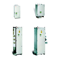
ABB DCS800 Installation Manual (70 pages)
Enclosed Converter
Brand:
ABB
| Category:
Industrial Electrical
| Size: 2.24 MB
Table of Contents
Safety Instructions
4
What this Chapter Contains
4
To Which Products this Chapter Applies
4
Usage of Warnings and Notes
4
Installation and Maintenance Work
5
Grounding
6
Mechanical Installation
8
Operation
9
EMC Standards
11
EMC Requirements for Plants and Machines in the EU
11
Conformity Procedure
11
Important Instructions for Plants with Line Filters
12
Table of Contents
13
Introduction to this Manual
15
How to Use this Manual
15
Contents of this Manual
15
Associated Publications
15
Inquiries
16
Mechanical Installation
17
Required Tools
17
Cabinet Construction
17
Moving of the Shipping Splits
18
Working Order of the Mechanical Installation
20
Fastening the Shipping Split to the Floor
22
Fastening Clamps 3AFE 64347683
22
Holes Inside the Cabinet
23
Layout of Bottom Plates
25
Cable Conduit below the Cabinet
34
Vibration Dampers (Marine Versions)
35
Joining the Shipping Splits
36
Working Order
36
Connecting the AC Busbar and the PE Busbar
38
Filter and Ventilation
39
Filters
39
Air Duct Outlet for Enclosed Converters with D6 / D7 Modules
40
Air Baffle Plates
40
Electrical Installation
42
Insulation Checks
42
Mains Fuses
42
Cabling Instructions
43
Power Cables
43
Control / Signal Cables
43
Co-Axial Cables
45
Relay Cable
45
Control Panel Cable
45
Optical Cables
45
Fieldbus Cables
45
Connection Example in Accordance with EMC
46
Cross-Sectional Areas -Tightening Torques
48
Cable Connections
52
Mains Cable Connection
52
Low Power Supply
52
High Power Supply
52
Motor Cable Connection
54
Cable Tray or Bus Duct
54
Mechanical Cable Connections
54
Location of Cable Connections Within the Cabinet
54
Motor Cable Connection
55
Conductive Sleeves
55
Cable Entry
55
Control Cable Connection
56
EMC Grounding at the Cable Entry
56
Routing the Cables
59
Finger Protection
63
Installation Checklist
64
Preventive Maintenance
66
Recommended Regular Maintenance
66
Air Filters
66
Cooling Air Pressure Switch in Converter Modules Type D5 / D6 / D7
66
Fan
66
Heatsink
66
Internal High Current Connections in Converters Type D7
66
Relays and Electrical Connections
67
ABB DCS800 Installation And Start-Up Manual (66 pages)
Rebuild Kits Drives
Brand:
ABB
| Category:
DC Drives
| Size: 2.55 MB
Table of Contents
Table of Contents
5
How to Use this Manual
7
Contents of this Manual
7
Associated Publications
7
Basic Selection
9
Technical Preconditions and Limits
9
Selecting the Suitable Rebuild Kit
9
Hardware Conditions
10
Drive´s Design Conditions
11
Conditions Caused by the Application
11
Type Coding and Accessories
12
Hardware
15
Basic Components of the DCS800-R Kit
15
Housing for Main Electronics
15
Pre-Assembled Part
16
Loose Parts
16
Optional Parts
17
Dimensions Main Electronic Housing
18
Environmental Conditions
19
Pulse Transformer Board SDCS-PIN-48
21
Wiring
21
Measurement Board SDCS-PIN-51
22
Wiring
24
Fastening
24
PTC Temperature Sensor
24
HW Type Coding
24
Voltage Coding
25
Nominal Current Coding
25
Additional Settings
27
Interface Board SDCS-REB-1
28
Power Supply
29
Functionality
30
Fastening
30
Diagram
31
Interface Board SDCS-REB-3
32
Firing Pulses
32
Signal Flow and Thyristor Designation
32
Design Hints
34
Signal Handling
34
Plug Connectors X1113: and X2113
35
Interfacing the Electronics and Thyristors
37
Connection for 2-Quadrant Application - no Parallel Thyristors
37
Connection for 4-Quadrant Application - no Parallel Thyristors
38
Connection for 4-Quadrant Application - Parallel Thyristors
39
Connection for 2-Quadrant Application - Parallel Thyristors
40
Background for the Figures of this Chapter
41
Hints for Cabling
53
Safety Instructions
55
What this Chapter Contains
55
To Which Products this Chapter Applies
55
Use of Warnings and Notes
55
Installation and Maintenance Work
56
Grounding
57
Mechanical Installation
58
Operation
58
Start-Up
61
What this Chapter Contains
61
Safety Instructions
61
Points to be Observed Because of the Situation
61
Maintenance Work
62
Tools
62
Measurements with the "Old" Equipment Still Working
62
Mounting the Kit
63
Wiring the Kit
63
Commissioning the Kit
64
ABB DCS800 Service Manual (67 pages)
Brand:
ABB
| Category:
DC Drives
| Size: 3.5 MB
Table of Contents
Safety Instructions
5
To Which Products this Chapter Applies
5
Usage of Warnings and Notes
5
Installation and Maintenance Work
6
Table of Contents
7
Type Code
8
Current and Voltage Ratings
10
Fault Tracing Thyristors
12
Tools
12
For Commissioning and Fault Tracing
12
Additionally for Service and Preventive Maintenance
13
How to Detect a Faulty Thyristor
13
A Fuse Is Blown
13
DC-Current Pulses Measured by an Oscilloscope
14
Thyristor Diagnosis
14
Ripple Monitor
14
How to Find a Faulty Thyristor
15
Converters Size D1 to D4 (20
15
Blown Fuses
15
Install New Thyristor Modules
19
Remove Faulty Onboard Bridge (V1)
21
Install New Onboard Bridge (V1)
21
Remove Faulty Thyristor
22
Install New Thyristor
23
Exchange of Thyristors for Size D6
27
Installation of "Disc Type" Thyristor in Converters Size D6 (1900
27
Required Tools
27
Disk Type Thyristors
28
BCT Thyristors
29
General
40
How to Remove the Converter Fan in a Frame D6
54
How to Remove the Converter Fan in a Frame D7
54
ABB DCS800 Quick Manual (52 pages)
Brand:
ABB
| Category:
DC Drives
| Size: 10.53 MB
ABB DCS800 Firmware Manual (20 pages)
Brand:
ABB
| Category:
DC Drives
| Size: 0.14 MB
Table of Contents
Table of Contents
2
Revision Information
3
What Revision Do I Have
3
What's Different with this Revision
3
Introduction
4
Macros
4
Macro Configuration Tables
5
DC Contactors With/Without Dynamic Braking
8
AC Contactors
10
Field Heating
11
Saving and Restoring a Parameter Set
13
Adaptive Programming
14
Using Spare Control Bits
14
The Importance of Bset (Bit Set)
14
Configuring and Displaying Digital Inputs and Outputs
16
Appendix A - Macro Parameter Lists
17
Advertisement
Related Products
ABB DCS880 series
ABB DCS880-S series
ABB DCS800-EP
ABB DCS800-A
ABB DCS800-S01-0125-05
ABB DCS800-S01-0090-05
ABB DCS800-S01-0065-05
ABB DCS800-EP1-0230-05
ABB DCS800-EP2-0260-05
ABB DCS800-EP1-0470-05
ABB Categories
Industrial Equipment
Controller
Measuring Instruments
Battery Charger
DC Drives
More ABB Manuals
Login
Sign In
OR
Sign in with Facebook
Sign in with Google
Upload manual
Upload from disk
Upload from URL