ABB DCS800 Hardware Manual
Hide thumbs
Also See for DCS800:
- Service manual (158 pages) ,
- Installation manual (70 pages) ,
- Installation and start-up manual (66 pages)
Table of Contents
Advertisement
Quick Links
Advertisement
Table of Contents

Related Manuals for ABB DCS800


Summary of Contents for ABB DCS800
- Page 1 DCS800 Hardware Manual DCS800 Drives (20 to 5200 A)
-
Page 2: Dcs800 Drive Manuals
3AFE63988235 DDCS Branching Units - User´s Manual 3BFE64285513 DCS800 Applications PLC Programming with CoDeSys CoDeSys_V23 61131 DCS800 target +tool description - Application Program 3ADW000199 DCS800 Crane Drive DCS800 Crane Drive Manual suppl. 3AST004143 R0101 DCS800 Crane Drive Product note DCS800 Winder ITC... - Page 3 DCS800 Drives 20 to 5200 A Hardware Manual 3ADW000194R0611 Rev F EFFECTIVE: 15.09.2008 © 2008 ABB Automation Products GmbH. All rights reserved. 3ADW000194R0611 DCS800 Hardware Manual f us...
- Page 4 3ADW000194R0611 DCS800 Hardware Manual f us...
-
Page 5: Safety Instructions
To which products this chapter applies This chapter applies to the DCS800... Size D1 to D7and field exciter units DCF800... Use of warnings and notes There are two types of safety instructions throughout this manual: warnings and notes. -
Page 6: Installation And Maintenance Work
Depending on the external wiring, dangerous voltages (115 V, 220 V or 230 V) may be present on the terminals of relay outputs SDCS-IOB-2, RDIO. • DCS800 with enclosure extension: Before working on the drive, isolate the whole drive from the supply. Safety instructions... -
Page 7: Grounding
• As the normal leakage current of the drive is higher than 3.5 mA AC or 10 mA DC (stated by EN 50178, 5.2.11.1), a fixed protective earth connection is required. Safety instructions 3ADW000194R0611 DCS800 Hardware Manual f us... -
Page 8: Fibre Optic Cables
• DCS800 Size D4...D7: The drive is heavy. Do not lift it alone. Do not lift the unit by the front cover. Place the unit only on its back. DCS800 Size D6/D7: The drive is heavy. Lift the drive by the lifting lugs only. -
Page 9: Operation
- which may require stricter safety regulations (e.g. protection against contact by children or similar). These additional safety measures for the installation must be provided by the customer during assembly. Safety instructions 3ADW000194R0611 DCS800 Hardware Manual f us... - Page 10 Note: • When the control location is not set to Local (L not shown in the PC tool status row), the stop key on the control panel will not stop the drive. Safety instructions 3ADW000194R0611 DCS800 Hardware Manual f us...
-
Page 11: Table Of Contents
Armature circuit converter DCS800-S0x D1...D4 ........17... - Page 12 DCS800 panel cable ........
- Page 13 DC-DC transducer A92 ........... . . 102 Table of contents 3ADW000194R0611 DCS800 Hardware Manual f us...
- Page 14 Other cables ..............133 Table of contents 3ADW000194R0611 DCS800 Hardware Manual f us...
-
Page 15: The Dcs800
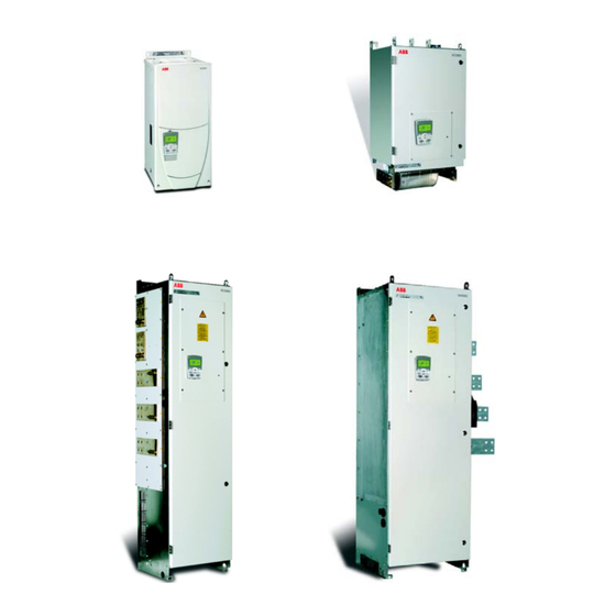
The DCS800 What this chapter contains This chapter describes briefly the operating principle and construction of the converter modules in short. The DCS800 The DCS800-S size D1...D7 are intended for controlling DC motors. Size D1...D4 Size D5 20...1000 A 900...2000 A... -
Page 16: Type Code
Type code The type code contains information on the specifications and configuration of the drive. The first digits from left express the basic configuration (e.g. DCS800-S01- 2005). The optional selections are given thereafter, on the name plate by plus code. -
Page 17: Main Circuit And Control
600 V units are always without Onboard field exciter Three-phase field supply DCF503B0050 DCF 803 / 804 DCF504B0050 also possible On Board FEX PIN 4 Memory Card Slot 4 optical fibre optical fibre AIMA The DCS800 3ADW000194R0611 DCS800 Hardware Manual f us... -
Page 18: Armature Circuit Converter Dcs800-S0X D5
Armature circuit converter DCS800-S0x D5...D7 Three-phase field supply DCF503B0050 DCF 803 / 804 DCF504B0050 also possible FEX 425 internal ** Memory Card Slot 4 optical fibre optical fibre AIMA The DCS800 3ADW000194R0611 DCS800 Hardware Manual f us... -
Page 19: Rebuild System Dcs800-R0X
Rebuild system DCS800-R0x Three-phase field supply DCF503B0050 DCF 803 / 804 DCF504B0050 also possible SDCS-FEX 4 internal SDCS-CCB4 Memory Card Slot 4 optical fibre optical fibre AIMA The DCS800 3ADW000194R0611 DCS800 Hardware Manual f us... - Page 20 The DCS800 3ADW000194R0611 DCS800 Hardware Manual f us...
-
Page 21: Mechanical Installation
Example labels are shown below. Type designation label Rated input voltage Rated internal field exciter current Rated input current Rated output current Rated fan voltage Plus code Mechanical installation 3ADW000194R0611 DCS800 Hardware Manual f us... -
Page 22: Before Installation
COOL AREA max.+40 °C (+104 °F) Air baffle plate Main air flow in Cooling w baffle.dsf Airflow Lead the exhaust cooling air away from the unit above. Distances see chapter Dimensional drawings Mechanical installation 3ADW000194R0611 DCS800 Hardware Manual f us... -
Page 23: Terminal Options Converter Size D1
Bottom view of lug bar mounted on a D4 module Terminal cover according to VBG 4 regulations For converter modules D1...D4 we provide shrouds for protection against contact Id No. Remark 3ADT631137P0001 D1...D2 3ADV400208P0001 3ADV400207P0001 Mechanical installation 3ADW000194R0611 DCS800 Hardware Manual f us... - Page 24 Mounting the D1/D2 cover by using the excisting lateral pins and than swing downward to snap-in at the terminal row. D3 and D4 mounting is accordingly, without the snap-in mechanism. Examples for covering the DC main terminals on D3 (left) and D4 (right) converter modules. Mechanical installation 3ADW000194R0611 DCS800 Hardware Manual f us...
-
Page 25: Mounting The Converter Module D6 Inside An Enclosure
The converter module is equipped with a thread hole at left side. Because of that the length of the remaining threads is limited to 35 mm (see drawing below). max. 35mm A6_li_air_inlet_c.dsf 468.2 Example right side connection Mechanical installation 3ADW000194R0611 DCS800 Hardware Manual f us... -
Page 26: Mounting The Converter Module D7 Inside An Enclosure
To avoid circulating air inside the enclosure it is rec- ommended to make sure the exhaust air leaves the enclosure. Do not have loose cables. The air flow from fan will destroy the cables! Mechanical installation 3ADW000194R0611 DCS800 Hardware Manual f us... -
Page 27: Planning The Electrical Installation
Always follow local regulations. Note: If the recommendations given by ABB are not followed, the drive may experience problems that the warranty does not cover. Reference: Technical Guide - publ. no.: 3ADW000163 To which products this chapter applies This chapter applies to the DCS800-S Size D1...D7. - Page 28 690 V line voltage • are based on a duty cycle • can be used for DCS800 as armature converter as well as field converter but rated line choke current must be considered.
-
Page 29: Line Reactors Ll1
DCS800-S01-1500-04/05/06/07 DCS800-S02-1500-04/05/06/07 ND15 on request DCS800-S01-2000-04/05 DCS800-S02-2000-04/05 ND16 on request DCS800-S01-2000-06/07 ND16 * on request * with forced cooling (1m/s) Fig. 1 Fig. 2 Fig. 3 Fig. 4 Fig. 5 Planning the electrical installation 3ADW000194R0611 DCS800 Hardware Manual f us... -
Page 30: Line Reactors Ll1 For North America
KLR300BCB KLR300ECB DCS800-S01-0590-06 DCS800-S02-0650-06 KLR600BCB KLR600ECB DCS800-S01-0900-06 DCS800-S02-0900-06 KLR750BCB KLR750ECB DCS800-S01-1500-06 DCS800-S02-1500-06 KLR1250BCB KLR1250ECB Recommended AC Line Reactors are available directly from TCI. For information, see their web page www.transcoil.com Planning the electrical installation 3ADW000194R0611 DCS800 Hardware Manual f us... -
Page 31: Aspects Of Fusing For The Armature-Circuit And Field Supplies Of Dc Drives
Adequate protection against short-circuit and earth fault, as depicted in the EN50178 standard, is possible only with appropriate semiconductor fuses. Semiconductor Semiconductor fuses fuses DCS converter DCS converter 4-Q resp. 2-Q non-regen. 2-Q regenerative Semiconductor fuses Planning the electrical installation 3ADW000194R0611 DCS800 Hardware Manual f us... -
Page 32: Conclusion For The Field Supply
Only pure HRC fuses or miniature circuit-breakers may be used. Semiconductor fuses would be destroyed, for example, by the transformer’s starting current inrush. F3.2 F3.1 Configurations for field supplies ND30 / F3.3 built-in F3.1 FF_ASP_b.dsf Planning the electrical installation 3ADW000194R0611 DCS800 Hardware Manual f us... -
Page 33: Semiconductor Type F1 Fuses And Fuse Holders For Ac And Dc Power Lines
Table below lists the fuse currents with respect to the table above. The fuses can be sized according to the maximum field current. In this case take the fuse, which fits to the rated field current levels. Planning the electrical installation 3ADW000194R0611 DCS800 Hardware Manual f us... -
Page 34: Single-Phase Transformer T3 For Field Supply To Match Voltage Levels
T 3.11 ≤ 12 A T 3.12 DCF803/4-0050 ≤ 16 A T 3.13 DCF803/4-0050 ≤ 30 A T 3.14 ≤ 50 A T 3.15 Autotransformer data (details see chapter Technical Data) Planning the electrical installation 3ADW000194R0611 DCS800 Hardware Manual f us... -
Page 35: Single-Phase Commutating Reactor
This function detects current to ground. If needed, the analogue input AI4 of the SDCS-IOB-3 board has to be activated, a current signal of the three phase currents should be supplied to AI4 by a current transformer. Planning the electrical installation 3ADW000194R0611 DCS800 Hardware Manual f us... -
Page 36: Emc Filters
(IT networks). According to EN 61800-3 filters are not needed in industrial zone (Second Environment) for DCS800 drives above 100 A rated current. For rated currents below 100 A the filter requirement is identical to Light Industry (First Environment). - Page 37 Then a field supply unit does not need its own filter. If the phase to neutral voltage shall be taken (230 V in a 400 V line) then a separate filter is necessary. ABB offers such filters for 250 V and 6...30 A. Filter type ➀...
- Page 38 Planning the electrical installation 3ADW000194R0611 DCS800 Hardware Manual f us...
- Page 39 Unscreened cable with restriction of sensitive communication equipment. able to cope with the commutation gaps caused by the power converter. In some cases, commutating reactors will be required. Planning the electrical installation 3ADW000194R0611 DCS800 Hardware Manual f us...
-
Page 40: Converters D1
Converters D1...D4 drive configuration using ’on board’ field exciter Wiring the drive according to this diagram offers the highest degree of monitoring functions done by the drive. Planning the electrical installation 3ADW000194R0611 DCS800 Hardware Manual f us... -
Page 41: Converters D5 Drive Configuration Using 'Fex-425-Int' Field Exciter
Field converters FEX-425- Int are equipped with their own synchronization and can be supplied from an independent net. FEX-425-Int can be supplied separate max. 500 V (3-phase), or 2- phase. Planning the electrical installation 3ADW000194R0611 DCS800 Hardware Manual f us... -
Page 42: Converters D5
Field converters DCF803 / DCF804 are equipped with their own synchronization and can be supplied from an independent net. DCF803-0035 can be supplied with 3-phase aux. supply. Planning the electrical installation 3ADW000194R0611 DCS800 Hardware Manual f us... -
Page 43: Converters D1
Converters D1...D3 3-phase field exciter configuration Wiring the drive according to this diagram offers the highest degree of monitoring functions done by the drive. Planning the electrical installation 3ADW000194R0611 DCS800 Hardware Manual f us... -
Page 44: Start, Stop And E-Stop Control
If the drive has not finished the function within the K15 timer setting, the drive must get the command to switch OFF the current via K16. After K16 timer set has elapsed the main contactor is opened independent of the drives status. Planning the electrical installation 3ADW000194R0611 DCS800 Hardware Manual f us... - Page 45 10.23 DCBreakAck Main contactor 6.03 b 7 DCS800 Dyn Brake 6.03 b 8 'on board' field exciter Converter module DC Contact US 6.03 b 10 X10: K1.1 DC cont us.dsf Planning the electrical installation 3ADW000194R0611 DCS800 Hardware Manual f us...
-
Page 46: Drive Configuration With Reduced Components
Wiring the drive according to this diagram gives the same control performance, but a lower degree of flexibility. Dynamic Braking keeps the main contactor K1 in state ON during braking. Planning the electrical installation 3ADW000194R0611 DCS800 Hardware Manual f us... -
Page 47: Fan Cooling
Temperature detector: internal connected ➀ ➀ Increased losses due to increased current with a blocked rotor will not result in a winding temper- ature, higher than permissible for the insulation class being involved. Planning the electrical installation 3ADW000194R0611 DCS800 Hardware Manual f us... - Page 48 D6 and D7 power section isolated PTC thermistor is used for air entry temperature. The detector thus measures the power section’s radiated heat and any Planning the electrical installation 3ADW000194R0611 DCS800 Hardware Manual f us...
-
Page 49: Thermal Overload And Short-Circuit Protection
Always protect the input cable with fuses. Size the fuses according to local safety regulations, appropriate input voltage and the rated current of the drive (see chapter Technical Data). High-speed semiconductor fuses provide short-circuit protection, but don’t provide thermal overload protection. Planning the electrical installation 3ADW000194R0611 DCS800 Hardware Manual f us... -
Page 50: Cross-Sectional Areas - Tightening Torques
1 mm²/ AWG 16 2.5 mm²/ AWG 13 4 mm²/ AWG 11 6 mm²/ AWG 10 6 mm²/ AWG 10 6 mm²/ AWG 10 Tightening torque 1.5...1.7 Nm Planning the electrical installation 3ADW000194R0611 DCS800 Hardware Manual f us... -
Page 51: Typical Cable Sizing And Tightening Torque - North America
125% of the rated drive input current. If the overcurrent protection (e.g. circuit breaker) is sized larger than this, then larger ground cables will need to be determined manually. Planning the electrical installation 3ADW000194R0611 DCS800 Hardware Manual f us... -
Page 52: Selecting The Control Cables
! Never mix 24 VDC and 115/230 VAC signals in the same cable. DCS800 panel cable The cable connection of the DCS800 panel to the drive must not exceed 3 meters (10 ft). The cable type tested and approved by ABB is used in control panel option kits. -
Page 53: Connection Of A Motor Temperature Sensor To The Drive I/O
3. An external thermistor relay is used. The insulation of the relay must be rated for the same voltage level as the main circuit of the drive. Planning the electrical installation 3ADW000194R0611 DCS800 Hardware Manual f us... - Page 54 Planning the electrical installation 3ADW000194R0611 DCS800 Hardware Manual f us...
-
Page 55: Electrical Installation
(C1, D1) or (F+, F-) and the Protective Earth by using a measuring voltage of 1 kV DC. The insulation resistance must be higher than 1 Mohm. C1, D1 F+, F- Electrical installation 3ADW000194R0611 DCS800 Hardware Manual f us... -
Page 56: It (Ungrounded) Systems
U1, V1, W1 Connecting the power cables Grounding and screening of power cables see manual Technical Guide, see Reference Cross sectional areas and tightening torques of power cable see chapter Planning the electrical installation Electrical installation 3ADW000194R0611 DCS800 Hardware Manual f us... -
Page 57: Location R-Extension And Interface Modules
R-Fieldbus module SLOT 2 R IO Extension module Interface connector SLOT 3 X2: SDCS-IOB-3 R IO Extension module X1: SDCS-IOB-2 R DDCS interface board X34: PCTool DriveWindow Light AP Tool Commissioning assi- stant Electrical installation 3ADW000194R0611 DCS800 Hardware Manual f us... -
Page 58: I/O Board Configuration
I/O´s: not isolated digital I/O´s: all isolated by means of encoder input: isolated optocoupler/relay, the current source for: PT100/PTC element signal status is indicated by LED current source for: PT100/PTC element Electrical installation 3ADW000194R0611 DCS800 Hardware Manual f us... -
Page 59: Pulse Encoder Connection
Pulse encoder connection Connecting a pulse encoder to the DCS800 converter The connection diagram for a pulse encoder to the electronics of a DCS converter is quite similar, if the SDCS-CON-4 or the SDCS-IOB-3 is used. The basic difference between these 2 boards is the galvanically isolated circuit and pulse receivers via opto coupler on the SDCS-IOB-3 board. -
Page 60: Pulse Encoder Receiver
6=park 10-11 +24V 9=park 14-15 16-17 differential current source X5:2 0V / GND SDCS-IOB-3 ENCODER INPUT A X5:10 13-14 In any case, if SDCS-IOB-3 is used, see required settings of SDCS-CON-4 board Electrical installation 3ADW000194R0611 DCS800 Hardware Manual f us... - Page 61 1 x 24 AWG 12 x 24 AWG 164 to 328 ft 2 x 24 AWG 12 x 24 AWG 328 to 492 ft 3 x 24 AWG 14 x 24 AWG Electrical installation 3ADW000194R0611 DCS800 Hardware Manual f us...
-
Page 62: Connecting The Signal And Control Cables
Not allowed unless the 24 V Lead 24 V and 115/230 V cable is insulated for 230 V or control cables in separate insulated with an insulation ducts inside the cabinet. sleeving for 115/230 V. Electrical installation 3ADW000194R0611 DCS800 Hardware Manual f us... -
Page 63: Dcs Link Wiring
1 Mailbox function for peer to peer communication 2 Communication to field exciter DCF 804, DCF803 and three-phase field supply of DCS800 3 Communication for 12-pulse operation, DCS800 to DCS800 Cabling Every bus node requires the setting of Node number. - Page 64 The bus ground (GNDB) is isolated. It can be ground terminated at one point only. Example of two DCS800 D5 converters with FEX-425-Int internal field supply. CAN_Bus_termination_c.dsf DCS800 D5 Converter DCS800 D5 Converter SDCS-DSL SDCS-DSL FEX-425-Int FEX-425-Int S1100:2 S1100:2 GNDB...
-
Page 65: Installation Checklist
The external control connections inside the drive are OK. There are no tools, foreign objects or dust from drilling inside the drive. Drive, motor connection box and other covers are in place. Installation checklist 3ADW000194R0611 DCS800 Hardware Manual f us... - Page 66 Installation checklist 3ADW000194R0611 DCS800 Hardware Manual f us...
-
Page 67: What This Chapter Contains
Ignoring the safety instructions can cause injury or death. Maintenance intervals If installed in an appropriate environment, the drive requires very little maintenance. This table lists the routine maintenance intervals recommended by ABB. Maintenance Interval Instruction... -
Page 68: Heatsink
If the drive is operated in a critical part of a process, fan replacement is recommended once these symptoms start appearing. Replacement fans are available from ABB. Do not use other than ABB specified spare parts. -
Page 69: Technical Data
(1 m dis- Vibration Shock Transport in Short circuit withstand rating tance) original Package The DCS800 is suitable for use in a circuit capa- ble of delivering not more than: as module enclosed conv. as module 55 dBA 54 dBA 1.2 m... - Page 70 • or on request >600 V to 990 V EN / IEC xxxxx see table EN / IEC types: on request above. (for details see table Available for converter above) modules including field exciter units. Technical data 3ADW000194R0611 DCS800 Hardware Manual f us...
-
Page 71: Current Ratings - Iec Non Regenerative
Current ratings - IEC non regenerative The current ratings for the DCS800 with 50 Hz and 60 Hz supplies are given below. The symbols are described below the table. Power converter module currents with corresponding load cycles. The characteristics are based on an ambient temperature of max. 40°C and an elevation of max. -
Page 72: Current Ratings - Iec Regenerative
Note 2: Use the DriveSize PC tool for a more accurate dimensioning if the ambient temperature is below 40 °C (104 °F) or the drive is loaded cyclically. Duty cycle DCII DCIII DCIV 15 min 15 min 15 min 150% 100% 100% 150% 100% 200% 100% Technical data 3ADW000194R0611 DCS800 Hardware Manual f us... -
Page 73: Current Ratings - North America Non-Regenerative
110% overload for 60 seconds, then <= 100% for 10 minutes Standard Duty: 150% overload for 30 seconds, then <= 100% for 15 minutes Heavy Duty: 150% overload for 60 seconds, then <= 100% for 15 minutes Technical data 3ADW000194R0611 DCS800 Hardware Manual f us... -
Page 74: Current Ratings - North America Regenerative
110% overload for 60 seconds, then <= 100% for 10 minutes Standard Duty: 150% overload for 30 seconds, then <= 100% for 15 minutes Heavy Duty: 150% overload for 60 seconds, then <= 100% for 15 minutes Technical data 3ADW000194R0611 DCS800 Hardware Manual f us... -
Page 75: Control Board Sdcs-Con-4
Memory circuit SDCS-CON-4 board is equipped with FlashPROM which contains the firmware plus the stored parameters. Parameters handled by DCS800 panel or DWL, PCtool or by Serial communication parameter service are stored immediately in the FlashPROM. Parameters handled by cyclic serial communication (dataset table Group 90 - 92 and pointers group 51) are not stored in the Flash PROM. -
Page 76: Seven Segment Display
X1: and X2: are used to connect SDCS-IOB-2 and SDCS-IOB-3 board. see chapter Technical data X33: is used to connect DCS800 Panel. It can be connected direct via 40 mm jack or via CAT 1:1 cable (RJ45). X34: is used for download firmware for DWL and IEC61131 programming connection. - Page 77 X20 (Slot 4) is used for Memory Card, see description IEC61131 programming. Prepared function of: Slot 1 Slot 2 Slot 3 Slot 4 X10: X11: X20: RDIO / RAIO R... Fieldbus adapter SDCS-COM-8 Second fieldbus RMBA Memory Card Technical data 3ADW000194R0611 DCS800 Hardware Manual f us...
-
Page 78: Digital And Analogue I/O Connection Of The Sdcs-Con-4
Relay driver load Do not apply any reverse Relay driver voltages! * short circuit protected Con4_I_O-b.dsf ➀ gain can be varied in 15 steps between 1 and 4 by software para- meter Technical data 3ADW000194R0611 DCS800 Hardware Manual f us... -
Page 79: Interface Board Sdcs-Com-8
Interface Board SDCS-COM-8 This board must be used together with a DCS800 to provide same serial communication DDCS options as ACS800. Furthermore the board is equipped with four optical channels (max. data transmission speed is 4 Mb for each optical channel): •... -
Page 80: Ch2 Sdcs-Com-8 Master-Follower Connections
0, 1, 2 ..8 NDBU-95 30 m plastic optic fibre AC80 Ch0 Drive Bus com8_bus conn_a.dsf AC 800M CI 858 Drive Bus Module PEC800 CI 858 Drive Bus Module FCI (CI 810 Adapter module) Technical data 3ADW000194R0611 DCS800 Hardware Manual f us... -
Page 81: Ch0 Connection To Overriding Control (Nxxx Fieldbus Adapter)
30 m - SDCS-COM-8 Rev D and higher max. 20 m instead of DriveWindow NETA internet module can be connected, see NETA Internet/Ethernet Manual PCI/PCMCIA 3AFE64605062 adapter (PC) NDPC-12 (Laptop) NDPA-02 com8_bus conn_a.dsf Technical data 3ADW000194R0611 DCS800 Hardware Manual f us... -
Page 82: Ch3 Star Connection To Pc Tool Drivewindow
...8 NETA internet module can be connected, NETA Internet/Ethernet see Manual Branching 3AFE64605062 unit Plastic opt. fibre Silicat max. 30 m max. 200 m PCI/PCMCIA adapter (PC) NDPC-12 (Laptop) NDPA-02 com8_bus conn_a.dsf Technical data 3ADW000194R0611 DCS800 Hardware Manual f us... -
Page 83: Ddcs Branching Unit Ndbu-95
DDCS Branching unit NDBU-95 DDCS Branching Unit (DBU) is used (for DCS 600/DCS800) to implement the star topology of DDCS link. This allows a slave unit to fail or become unpowered without disabling the communication. The NDBU receives messages from the master (PC) and sends them to all the slave units simultaneously. -
Page 84: Sdcs-Dsl Board
120 ohm Termination 200 kOhm no termination; park position Ground termination 200 kOhm R-C ground termination X54:1 0 Ohm ground termination no termination; park position RS 485 communication Remarks no isolation DSL-4_dia_a.dsf Technical data 3ADW000194R0611 DCS800 Hardware Manual f us... -
Page 85: Digital I/O Board Sdcs-Iob-2
** W100 as printed circuit DI 8 iob2x1_d.dsf default value There is a card holder available as option for fastening the SDCS-IOB-2 board. For more information see chapter Dimensional drawings. Technical data 3ADW000194R0611 DCS800 Hardware Manual f us... - Page 86 +48V connection must be done from either X7:1 and/or X7:2 to ground of conductive support the DCS800 module. In default condition ground is identical to the iob2x2_b.dsf converter's frame. If the inputs are supplied by any external source (+48 V DC, 115 V AC or 230 V AC) the neutral line / - line must be connected to either X7:1 or X7:2.
-
Page 87: Analogue And Encoder I/O Board Sdcs-Iob-3
S4 jumper setting on SDCS-CON-4 has to be made There is a card holder available as option for fastening the SDCS-IOB-3 board. For more information see chapter Dimensional drawings. Technical data 3ADW000194R0611 DCS800 Hardware Manual f us... - Page 88 For input AI4 there are the following configurations available: - input range ”20mA” , or - input range ”10V”, or - earth fault monitoring by Isum not equal to zero via X3:11 and X3:12 Technical data 3ADW000194R0611 DCS800 Hardware Manual f us...
-
Page 89: Power Supply Board Sdcs-Pow-4
Power Supply Board SDCS-POW-4 The SDCS-POW-4 board is designed for DCS800 converter modules and is mounted on the electronic support. This board is used for all types of modules type D5, D6 and D7 (>1000 A and rebuild system DCS800-R). -
Page 90: Interface Board Sdcs-Pin-4
Interface Board SDCS-PIN-4 General The SDCS-PIN-4 board is designed for DCS800 Converter modules sizes D1 up to size D4 (20 A...1000 A) the board has three different functions: 1. Power supply of CON-4 board and the connected plug-in modules 2. Control of armature bridge and measurement 3. -
Page 91: Power Supply
Tolerance -15%/+10% -15%/+10% the mains buffering time. More detailed data Frequency 45 Hz ... 65 Hz 45 Hz ... 65 Hz is available on request via your ABB Power consump- 120 VA 120 VA representative. tion ≤ 60 W ≤ 60 W... -
Page 92: Armature Circuit Interface
AWG 10 AWG 10 AWG 10 AWG 10 min. cross sectional area 1 mm² 2.5 mm² 4 mm² 6 mm² AWG 16 AWG 13 AWG 11 AWG 10 Fuse type KTK - 25 Technical data 3ADW000194R0611 DCS800 Hardware Manual f us... - Page 93 Typical armature circuit thyristor converter diagram with SDCS-PIN-4 board Technical data 3ADW000194R0611 DCS800 Hardware Manual f us...
-
Page 94: Power Interface Sdcs-Pin-46/Sdcs-Pin-48/Sdcs-Pin-5X
The following figures show the different connections between the SDCS-PIN-48 and SDCS-PIN-51 board depending on the application 2- or 4-quadrant and the construction type. The firing board SDCS-PIN-46 is used for converters DCS800-S02-2500, DCS800-S02-3000 double bridge D6 modules. 2-Quadrant application, no parallel thyristors - Construction type D5/D6/D7... - Page 95 Conductive see diagram power part supports line potential ! R123 X22 X122 Two PTC ..One PTC W10 W70 X12S X413S X13S X313S Isolating supports SDCS-PIN-51 Technical data 3ADW000194R0611 DCS800 Hardware Manual f us...
- Page 96 Settings of the SDCS-PIN-51 board if a DCS converter is equipped with it by ABB Current coding Construction type Current transf. ratio 2500:1 2500:1 4000:1 Rated current [A DC] 1200 1500 2000 1900 2050 2500 3000 2050 2600 3300 4000...
- Page 97 Typical armature circuit thyristor converter diagram with SDCS-PIN-48 and SDCS-PIN-51 boards for a 4-Quadrant D7 type converter 100R 120R 270R 560R Technical data 3ADW000194R0611 DCS800 Hardware Manual f us...
-
Page 98: Interface Board Sdcs-Sub-4
1-2 = automatic 2-3 = 230 V fix K301 K400 F400 F300 conducting point Relay Input output Aux. DO 8 supply Output field Pin4_SUB4 layout.dsf current Layout of SDCS-SUB-4 and location on SDCS-PIN-4 Technical data 3ADW000194R0611 DCS800 Hardware Manual f us... - Page 99 Typical armature circuit thyristor converter diagram with SDCS-PIN-4 and SDCS-SUB-4 board Technical data 3ADW000194R0611 DCS800 Hardware Manual f us...
-
Page 100: Galvanic Isolation - T90, A92
B (1.6 kV) Transformer T90 3ADT 745047 Secondary Terminals * * 12-pulse serial and sequential have a different selection between SConvScaleVolt (97.03) and the scaling of measurement channel. See 12-pulse manual for DCS 800. Technical data 3ADW000194R0611 DCS800 Hardware Manual f us... - Page 101 Typical armature circuit thyristor converter diagram with SDCS-PIN-48 and SDCS-PIN-51 boards for a 4-Q D7 type converter with galvanic isolation 100R 120R 270R 560R Technical data 3ADW000194R0611 DCS800 Hardware Manual f us...
-
Page 102: Dc-Dc Transducer A92
The voltage gain and frequency response is especially designed for DCS800 converters. Dimensions in mm Location of terminals Side view Buttom view 112.0 76.0 10.0 70.0 Gain selector 50.0 9 10 60.0 Technical data 3ADW000194R0611 DCS800 Hardware Manual f us... -
Page 103: Transformer T90
Put in the cable lug, swing in the shrowding cover and fasten the con- nection by turning the screw clockwise. 3 mm 5.2 x 7.7 118..120 Technical data 3ADW000194R0611 DCS800 Hardware Manual f us... - Page 104 Technical data 3ADW000194R0611 DCS800 Hardware Manual f us...
-
Page 105: Dimensional Drawings
Dimensional drawings Dimensional drawings of the DCS800 are shown below. The dimensions are given in milllimeters. Module D1 S = 5 mm S = 10 mm DCS800-S01-0020 DCS800-S01-0045 DCS800-S01-0065 DCS800-S01-0090 DCS800-S01-0125 48.5 DCS800-S02-0025 DCS800-S02-0050 DCS800-S02-0075 DCS800-S02-0100 DCS800-S02-0140 Module D2 DCS800-S01-0180... -
Page 106: Module D4
600 V types DCS800-S01-0590 DCS800-S02-0650 Weight appr. 38 kg f. M12 Power terminal: Busbar 40x5 mm Weight appr. 38 kg fan terminal Direction of air flow Earthing 147.5 195.5 240(PIN-4) 287.5(CON-4) D4_dim_b.dsf Dimensional drawings 3ADW000194R0611 DCS800 Hardware Manual f us... -
Page 107: Module D5
The upper and lower holes in the back plate of the converter should be used to fix the converter in that position. Dimensional drawings 3ADW000194R0611 DCS800 Hardware Manual f us... -
Page 108: Module D6
Module D6 458.2 DCS800-S0x-1900 DCS800-S0x-2050 DCS800-S0x-2500 Air outlet DCS800-S0x-3000 10x20 Weight appr. 180 kg Pressure switch Air entry A6_dim.dsf from the front, right, left and 468.2 back Dimensional drawings 3ADW000194R0611 DCS800 Hardware Manual f us... -
Page 109: Module D7 Left-Hand
Module D7 left-hand for M10 DCS800-S0x-2050-xxL DCS800-S0x-2600-xxL DCS800-S0x-3300-xxL DCS800-S0x-4000-xxL DCS800-S0x-4800-xxL DCS800-S0x-5200-xxL Weight appr. 315 kg Pressure switch for M10 A7_dim_a.dsf Busbars in mm: AC and DC 100 x 10 Dimensional drawings 3ADW000194R0611 DCS800 Hardware Manual f us... -
Page 110: Module D7 Right-Hand
Module D7 right-hand for M10 DCS800-S0x-2050-xxR DCS800-S0x-2600-xxR DCS800-S0x-3300-xxR DCS800-S0x-4000-xxR DCS800-S0x-4800-xxR DCS800-S0x-5200-xxR Weight appr. 315 kg Pressure switch for M10 A7_dim_a.dsf Busbars in mm: AC and DC 100 x 10 Dimensional drawings 3ADW000194R0611 DCS800 Hardware Manual f us... -
Page 111: Fuses Installed Inside The Converter
DCS800-S0x-2050-10 1800A 1250V UR 170M 7976 DCS800-S0x-2600-10 1800A 1250V UR 170M 7976 DCS800-S0x-3300-10 2500A 1250V UR 170M 7978 DCS800-S0x-4000-10 2500A 1250V UR 170M 7978 ➀ 12 fuses per bridge (2x per F1x) Dimensional drawings 3ADW000194R0611 DCS800 Hardware Manual f us... - Page 112 • finger protection cover • screen clamp (IOB-2x / IOB-3 not included) with universal Phoenix clamp 1202713 it is possible to mount the card holder on standard rail system in horizontally or vertically direction Dimensional drawings 3ADW000194R0611 DCS800 Hardware Manual f us...
-
Page 113: Accessories
U730 D800 S801 U731 R106 V110 X101 Mains R107 R108 Fex4_layout_a.dsf 24 V supply DSL Link X1:1 24 V DC X3:1 GND B X1:2 0 V DC X3:2 CAN L X3:3 CAN H Accessories 3ADW000194R0611 DCS800 Hardware Manual f us... -
Page 114: Electrical Data
The internal field exciter FEX425 is a ready installed field exciter in a D5 armature converter. The unit is based on a SCDS-FEX-4 board and contains also line fuses. The supply must be connected by independant line reactors located outside of the D5 module, see drawing in chapter The DCS800, section Armature circuit converter DCS800-S D5...D7. -
Page 115: Dcs Link Communication
==> S800 = 3 and S801 = 1 S801 Selection of communication speed is set by S1100 S1100:6 S1100:5 S1100:4 Baudrate Selection of armature converter, param kBaud * Switch_0-9.dsf [94.02] 1000 * see Parameter [94.08], [94.09] Accessories 3ADW000194R0611 DCS800 Hardware Manual f us... -
Page 116: Diagnosis
Fault Field AC supply voltage < 30V Fault Field AC supply voltage < 650V Fault maximum temperature heatsink Y=12 Fault Auxiliary voltage Y=14 Fault general hardware No RESET Y=15 Fault general software No RESET Accessories 3ADW000194R0611 DCS800 Hardware Manual f us... -
Page 117: Rs232-Port
600 V F303 FEX425 INTERNAL 35A(+) max. 500 V; 1- phase HW conf FEX4.dsf Further information about line reactors see sections Line reactor L3 (ND30) and Line reactors type ND401...413 (ND402) in this chapter. Accessories 3ADW000194R0611 DCS800 Hardware Manual f us... -
Page 118: Dimensions
U1 V1 W1 DCF803-0035.dsf earthing M6 DCF803-0035 36.5 S1100 for mounting on mounting plate provide hole with diameter of min 5 mm for thermal sensor 16A 5A D1 U1 V1 W1 DCF803-0016.dsf DCF803-0016 Accessories 3ADW000194R0611 DCS800 Hardware Manual f us... -
Page 119: Dcf505 / Dcf506 Overvoltage Protection
When the free-wheeling function is triggered, it will last until the DC current is less than appr. 0.5 A. During this time the relay contacts are closed. The overvoltage protection unit DCF 505 is suit- For motor field supply via DCS800-S01 (2-Q) or able for 2-Q converters DCS800-S01 with simple DCS800-S02 (4-Q) the overvoltage protection unit DCF non-motoric inductive load. - Page 120 - SDCS-FEP-1 for systems, used at line voltages up to 500 V; this board is equipped with a 1400 V trigger diode. - SDCS-FEP-2 for systems, used at line voltages up to 690 V; this board is equipped with a 1800 V trigger diode. Accessories 3ADW000194R0611 DCS800 Hardware Manual f us...
- Page 121 Weight appr. 8 kg X11 (F+) X12 (F-) MB_520_a.dsf Overvoltage Protection DCF 506-1200-51 DCF 506-1500-51 DCF 506-1500-71 Dimensions in mm Weight appr. 20 kg SDCS-FEP-1 (500 V) SDCS-FEP-2 (690 V) MB_1500_a.dsf f. M6 Accessories 3ADW000194R0611 DCS800 Hardware Manual f us...
-
Page 122: Fuses And Fuse Holders Iec
HxWxD [mm] Protec- OFAX ... tion OFAX 00 S3L 148x112x111 IP20 OFAX 1 S3 250x174x123 IP20 OFAX 2 S3 OFAX 2 S3 250x214x133 IP20 OFAX 3 S3 265x246x160 IP20 170H 3006 (IP00) 170H3006_a.dsf Accessories 3ADW000194R0611 DCS800 Hardware Manual f us... -
Page 123: Fuses And Fuse Holders - North America
FWP-450A-600A 7.09 2.84 5.72 4.19 0.53 0.38 FWP-700A-800A 6.63 2.844 5.562 5.062 0.625 0.25 0.875 Dimensions in inches. Fig. 1: 5-800 Amp Range Fig. 2: 900-1000 Amp Range Fig. 3: 1200 Amp Range Accessories 3ADW000194R0611 DCS800 Hardware Manual f us... -
Page 124: Line Reactors Iec
Line reactors type ND 01...ND 06 X, Y, Z A, B, C A, B, C X, Y, Z ND1_to_6_a.dsf Type mm² ND 01 ND 02 ND 03 ND 04 ND 05 ND 06 Accessories 3ADW000194R0611 DCS800 Hardware Manual f us... -
Page 125: Line Reactors Type Nd 07
ND 12 13x18 40x6 Line reactors type ND 13, 14 Line reactors type ND 15, 16 all busbars 40x10 all busbars 60x10 ±2 ±2 ±2 ø13 ø13 ±1 ±2 ND13_14_c.dsf ±2 ND15_16_c.dsf ±1 Accessories 3ADW000194R0611 DCS800 Hardware Manual f us... - Page 126 Line reactors type ND 17 ø14 verzinnt tin-plated ND17.dsf Accessories 3ADW000194R0611 DCS800 Hardware Manual f us...
-
Page 127: Line Reactors Type Nd 401
160 190 75 80 51 175 7 ND 402 200 220 105 115 75 200 7 Terminals: WAGO Type 202 UL File E45172 ø H tin-coated ø G ø G+5 F±1 E ±2 Accessories 3ADW000194R0611 DCS800 Hardware Manual f us... - Page 128 ND 411 345 350 205 270 175 115 12 2x11 ND 412 385 350 205 280 175 115 12 2x11 ND 413 445 350 205 280 175 115 12 2x11 ø H tin-coated øK AL ø E ±2 F ±2 Accessories 3ADW000194R0611 DCS800 Hardware Manual f us...
-
Page 129: Line Reactors - North America
Configuration B: For installations that require compliance with EN 61-800-3 or when AC and DC drives are on the same line. See Chapter “Planning the Electrical Installation” for additional information. Recommended AC Line Reactors are available directly from TCI. For information, see their web page www.transcoil.com. Accessories 3ADW000194R0611 DCS800 Hardware Manual f us... -
Page 130: Autotransformer T3
DCF503-0035 as well as FEX-425-Int Input voltage: 500 V Frequency: 50 / 60 Hz Type line reactor data L3 Weight Pow loss peak [μH] [kg] [W] [mm²] ND30 2x >500 16 4.5 Ø max 80 Accessories 3ADW000194R0611 DCS800 Hardware Manual f us... -
Page 131: Supply Transformer T2 For Electronics And Fan
The transformer is designed to work as a 230 V / 230 V transformer to open/ 230 V avoid ground loops. This is done via the 380 V and 600 V taping according to the left picture. 230 V 115 V T2_a.dsf Accessories 3ADW000194R0611 DCS800 Hardware Manual f us... -
Page 132: Optical Cables
HCS silica (double) with plastic jacket plug 50...200 m 3ADT 693356 Figure 1 blue black Figure 2 blue black black blue Figure 3 orange orange ∅ 5 mm black black Figure 4 blue blue ∅ 8 mm Accessories 3ADW000194R0611 DCS800 Hardware Manual f us... -
Page 133: Other Cables
IOB2-3 unscreened flat cab.dsf Screened cable for SDCS-CON-4 - SDCS-IOB-2/IOB-3 connection 1.4 / 3.2 / 4 m screen laid open Pull tab Pull tab (for cable (for cable marking) marking) SDCS-IOB-x SDCS-CON-x IOB2-3 screened flat cab.dsf Accessories 3ADW000194R0611 DCS800 Hardware Manual f us... - Page 134 ABB Automation Products Wallstadter Straße 59 68526 Ladenburg • GERMANY Telefon: +49(0)6203-71-0 Telefax: +49(0)6203-71-7609 www.abb.com/motors&drives *194R0611A8370000* *194R0611A8370000*...
Need help?
Do you have a question about the DCS800 and is the answer not in the manual?
Questions and answers