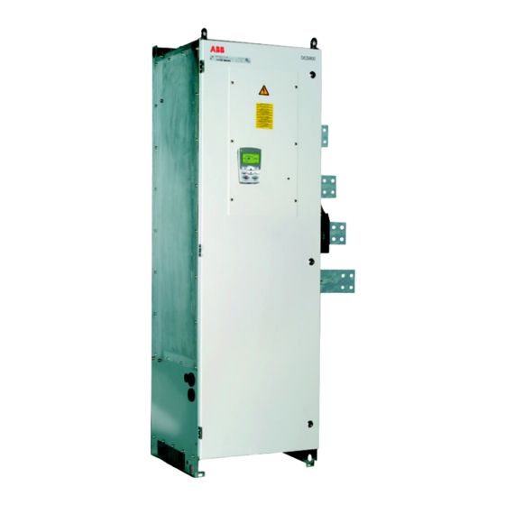
ABB DCS800 Firmware Manual
Hide thumbs
Also See for DCS800:
- Service manual (158 pages) ,
- Hardware manual (134 pages) ,
- Installation manual (70 pages)
Summary of Contents for ABB DCS800
- Page 1 DCS800 Firmware manual supplement for North America, Firmware Rev. 2.60 and Rev. 2.70 DCS800 Drives (20 to 5200 A)
-
Page 2: Table Of Contents
Using spare control bits The importance of BSet (Bit Set) Configuring and displaying digital inputs and outputs ............16 Appendix A – Macro parameter lists .................. 17 DCS800 Firmware manual supplement for North America (rev. 2.60, 2.70) Rev. b 5/30/2008... -
Page 3: Revision Information
Revision Information This supplement is dedicated to Revision 2.6 and Revision 2.7 of the DCS800 Firmware. Drives shipped after March, 2008 will most likely have this revision. What revision do I have? To determine your firmware revision number, check the value of signal: FirmwareVer (4.01). -
Page 4: Introduction
_________________________________________________________ Overview The DCS800 uses macro’s differently than the ACS800 and other ABB AC drives. In the DCS800, macro’s are mainly used to designate analog and digital inputs and outputs. Moreover, once a macro has been implemented, these designations are easily changed. -
Page 5: Macro Configuration Tables
2.6 and above, along with selection of hand or auto mode. In “hand” mode, speed select is via AI-1; in “auto” mode, speed select is via parameter 23.01. DCS800 Firmware manual supplement for North America (rev. 2.60, 2.70) Rev. b 5/30/2008... - Page 6 Table 1b: Macro Configurations: The analog and digital inputs and outputs shown in this table are automatically configured when you implement the macro identified in the top row. *New Macro DCS800 Firmware manual supplement for North America (rev. 2.60, 2.70) Rev. b 5/30/2008...
- Page 7 C, D, E ... Revision 2.6 allows you to freely switch between any macro, except factory, without changing motor or tuning parameters. Factory macro resets all parameters back to default. DCS800 Firmware manual supplement for North America (rev. 2.60, 2.70) Rev. b 5/30/2008...
-
Page 8: Dc Contactors With/Without Dynamic Braking
Parameter Lists: See appendix A for a complete list of parameter settings for each macro. DriveWindow Light: For basic instructions on DriveWindow Light (incl. communication settings), see the DCS800 Quick Guide which is included with every D1 – D4 drive. DC contactors with/without dynamic braking... - Page 9 Use digital output 8 (DO-8) to control the DC contactor. DO-8 is the only relay output in the DCS800 drive and is rated at 3 Amps at either 115/230 Vac or 24 Vdc. (Rated at 0.3 Amps at 115-230 Vdc.) Control of DO-8 is configured with parameters DO8Index (14.15) and DO8BitNo (14.16).
-
Page 10: Ac Contactors
The auxiliary contact will then give the StartStop input, initiating motion. If this is desired, use the following parameter instead of 10.21: • Parameter StartStop (10.16) = the acknowledge input number DCS800 Firmware manual supplement for North America (rev. 2.60, 2.70) Rev. b 5/30/2008... -
Page 11: Field Heating
Then the voltage-controlled field supply would work just fine. The new generation of drives, including all field supplies used with the DCS800, are current controlled, meaning that the field supply directly regulates field current. This means that field heating may no longer be necessary when this drive is employed. - Page 12 Page 148 - 152 group 10 parameters Start / Stop Select • Pages 180 – 181 group 21 parameters Start / Stop • Page 222 group 44 parameters Field Excitation DCS800 Firmware manual supplement for North America (rev. 2.60, 2.70) Rev. b 5/30/2008...
-
Page 13: Saving And Restoring A Parameter Set
Saving with SAVE AS: This function transfers the parameter set from the DCS800 to the PC. It is done as follows: 1. Connect to the DCS800 and go on line by clicking on File, then New Online Drive. 2. Click on File, then Save As…. Enter a file name and select a location. -
Page 14: Adaptive Programming
The current version of the control panel only supports one method of upload and download. The function DOWNLOAD APPLICATION is not currently available. UPLOAD: This function transfers the parameter set from the DCS800 drive to the control panel. It is done as follows: 1. - Page 15 11 while change, but the other bits will remain intact. For additional information See the DCS800 firmware manual: • Page 67 – 75 Adaptive Program Instructions • Page 76 – 98 Adaptive Program Function Blocks DCS800 Firmware manual supplement for North America (rev. 2.60, 2.70) Rev. b 5/30/2008...
-
Page 16: Configuring And Displaying Digital Inputs And Outputs
“I/O assistant” wizard in DriveWindows Light. Using DriveWindows Light 1. Connect to the DCS800 and go on line by clicking on File, then New Online Drive. 2. Click on Wizard, on the left side of the screen. -
Page 17: Appendix A - Macro Parameter Lists
DI-4 DI-4 NotUsed NotUsed NotUsed USI Sel 16.09 Compact Extended Extended Extended Extended Extended All others Default not changed not changed not changed not changed not changed DCS800 Firmware manual supplement for North America (rev. 2.60, 2.70) Rev. b 5/30/2008... - Page 18 ExtAlarmSel 30.32 NotUsed DI-4 NotUsed NotUsed DI-4 USI Sel 16.09 Extended Extended Extended Extended Extended All others not changed not changed not changed not changed not changed DCS800 Firmware manual supplement for North America (rev. 2.60, 2.70) Rev. b 5/30/2008...
- Page 19 Notes: DCS800 Firmware manual supplement for North America (rev. 2.60, 2.70) Rev. b 5/30/2008...
- Page 20 DCS800 Firmware manual supplement for North America (rev. 2.60, 2.70) Rev. b 5/30/2008...


Need help?
Do you have a question about the DCS800 and is the answer not in the manual?
Questions and answers