Sign In
Upload
Manuals
Brands
ABB Manuals
Controller
ACS580-07
ABB ACS580-07 Manuals
Manuals and User Guides for ABB ACS580-07. We have
4
ABB ACS580-07 manuals available for free PDF download: Hardware Manual, User Manual
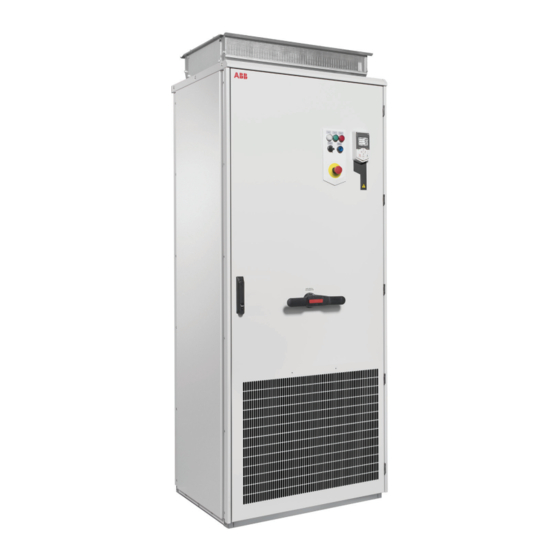
ABB ACS580-07 Hardware Manual (374 pages)
GENERAL PURPOSE DRIVES
Brand:
ABB
| Category:
Industrial Equipment
| Size: 57 MB
Table of Contents
Table of Contents
5
Table of Contents
9
Safety Instructions
17
Contents of this Chapter
17
Use of Warnings and Notes
17
General Safety in Installation, Start-Up and Maintenance
18
Electrical Safety in Installation, Start-Up and Maintenance
20
Electrical Safety Precautions
20
Additional Instructions and Notes
22
Printed Circuit Boards
23
Grounding
23
General Safety in Operation
24
Additional Instructions for Permanent Magnet Motor Drives
25
Safety in Installation, Start-Up, Maintenance
25
Safety in Operation
25
Introduction to the Manual
27
Contents of this Chapter
27
Target Audience
27
Purpose of the Manual
27
Categorization by Frame Size and Option Code
27
Quick Installation Flowchart
28
Terms and Abbreviations
28
Related Documents
29
Operation Principle and Hardware Description
31
Contents of this Chapter
31
Product Overview
32
Layout
34
General Information on the Cabinet Layout
34
Cabinet Layout - R4 and R5 (Bottom Entry and Exit of Cables)
35
Cabinet Layout - R6 and R7 (Bottom Entry and Exit of Cables)
36
Cabinet Layout - R4 to R7
37
H353)
37
Cabinet Layout - R8 and R9 (Bottom Entry and Exit of Cables)
38
Cabinet Layout - R8 and R9 (Top Entry and Exit of Cables, Options +H351 and +H353)
39
Mounting Plate - R4 to R9
40
Cabinet Layout - R10 and R11 (Bottom Entry and Exit of Cables)
42
Cabinet Layout - R10 and R11 (Top Entry and Exit of Cables, Options +H351 and +H353)
44
Cabinet Layout - Brake Resistor Cabling with Option +D150
45
Mounting Plate - R10 and R11
45
Cooling Air Flow
47
Door Switches and Lights
48
Main Switch-Disconnector Q1
48
Control Panel
48
Control by PC Tools
49
Common Mode Filter
49
Overview of Power and Control Connections
50
Descriptions of Options
51
Degree of Protection
52
Definitions
52
IP21 (UL Type 1)
52
IP42 (UL Type 1 Filtered) (Option +B054)
52
IP54 (UL Type 12) (Standard)
52
Cooling Air Inlet through Bottom of Cabinet (Option +C128)
52
UL Listed (Option +C129)
52
Channeled Air Outlet (Option +C130)
52
Plinth Height (Options +C164 and +C179)
53
Empty Cubicles on Right (Options +C196
53
Empty Cubicles on Left (Options +C199
53
EMC Filter (Option +E202)
53
D U /D T Filter (Option +E205)
53
Common Mode Filter (Option +E208)
53
Molded Case Circuit Breaker (MCCB, Option +F289)
53
Cabinet Heater with External Supply (Option +G300)
54
Terminals for External Control Voltage (Option +G307)
54
Output for Motor Space Heater (Option +G313)
54
Ready/Run/Fault Lights (Options +G327
54
Top Cable Entry/Exit (Options +H351 and +H353)
54
European Cable Entry (Option +H357)
55
Cable Conduit Entry (Option +H358)
55
Connectivity for Wired Remote Monitoring (Option +K496)
55
Connectivity for Wireless Remote Monitoring (Option +K497)
55
Additional Terminal Block X504 (Option +L504)
55
Thermal Protection with Pt100 Relays (Option +Nl506)
56
Starter for Auxiliary Motor Fan (Options +M600
56
What the Option Contains
56
Description
56
Type Designation Label
57
Type Designation Key
57
Basic Code
58
Option Codes
58
Mechanical Installation
61
Contents of this Chapter
61
Examining the Installation Site
61
Necessary Tools
62
Moving and Unpacking the Drive
62
Unpacking the Transport Package
64
Examining the Delivery
65
Lifting the Cabinet
65
Lifting Lugs
66
Moving the Cabinet after Unpacking
70
Moving the Cabinet on Rollers
71
Moving the Cabinet to Its Final Position
71
Attaching the Cabinet to the Floor and Wall or Roof
71
General Rules
71
Attaching the Cabinet (Non-Marine Units)
73
Alternative 1 - Clamping
73
Alternative 2 - Using the Holes Inside the Cabinet
74
Alternative 3 - Cabinets with Plinth Options +C164 and +C179
75
Miscellaneous
76
Cable Duct in the Floor below the Cabinet
76
Arc Welding
76
Air Inlet through the Bottom of the Cabinet (Option +C128)
76
Air Outlet Duct on the Cabinet Roof (Option +C130)
77
Calculating the Required Static Pressure Difference
78
Guidelines for Planning the Electrical Installation
79
Contents of this Chapter
79
Limitation of Liability
79
North America
79
Selecting the Supply Disconnecting Device
79
Selecting the Main Contactor or Breaker
79
Examining the Compatibility of the Motor and Drive
80
Protecting the Motor Insulation and Bearings
80
Requirements Tables
80
Requirements for ABB Motors, P
81
Requirements for ABB Motors, P
82
Requirements for Non-ABB Motors, P
83
Requirements for Non-ABB Motors, P
84
Abbreviations
84
Availability of D U /D T Filter and Common Mode Filter by Drive Type
85
Additional Requirements for Explosion-Safe (EX) Motors
85
HX_ and am
85
Additional Requirements for Braking Applications
85
Additional Requirements for ABB High-Output and IP23 Motors
85
Additional Requirements for Non-ABB High-Output and IP23 Motors
85
Additional Data for Calculating the Rise Time and the Peak Line-To-Line Voltage
86
Additional Note for Sine Filters
87
Selecting the Power Cables
88
General Guidelines
88
Typical Power Cable Sizes
88
Power Cable Types
88
Preferred Power Cable Types
88
Alternate Power Cable Types
89
Not Allowed Power Cable Types
90
Additional Guidelines - North America
90
Metal Conduit
91
Power Cable Shield
91
Grounding Requirements
92
Additional Grounding Requirements - IEC
93
Additional Grounding Requirements - UL (NEC)
93
Selecting the Control Cables
93
Shielding
93
Signals in Separate Cables
94
Signals that Can be Run in the same Cable
94
Relay Cable
94
Control Panel to Drive Cable
94
PC Tool Cable
94
Routing the Cables
94
General Guidelines - IEC
94
General Guidelines - North America
95
The Motor Cable
96
Separate Control Cable Ducts
96
Situations and against Thermal Overload
97
Protecting the Drive and Input Power Cable in Short-Circuit Situations
97
Protecting the Motor and Motor Cable in Short-Circuits
97
Protecting the Drive and the Power Cables against Thermal Overload
97
Protecting the Motor against Thermal Overload
98
Protecting the Motor against Overload Without Thermal Model or Temperature Sensors
98
Protecting the Drive against Ground Faults
98
Residual Current Device Compatibility
98
Implementing the Emergency Stop Function
99
Implementing the Safe Torque off Function
99
Implementing the Power Loss Ride-Through Function
99
Using Power Factor Compensation Capacitors with the Drive
99
Using a Safety Switch between the Drive and the Motor
100
Implementing an ATEX-Certified Motor Thermal Protection
100
Controlling a Contactor between Drive and Motor
100
Implementing a Bypass Connection
101
Protecting the Contacts of Relay Outputs
101
Implementing a Motor Temperature Sensor Connection
102
Connecting a Motor Temperature Sensor to the Drive through an Option Module
103
Supplying Power for the Auxiliary Circuits
103
Electrical Installation
105
Contents of this Chapter
105
Warning
105
Attaching the Device Stickers on the Cabinet Door
105
Layout of the Cable Entries (Frames R4
106
Layout of the Cable Entries (Frames R10 and R11)
107
Connecting the Motor Cable at the Motor End
107
Measuring the Insulation
108
Measuring the Insulation Resistance of the Drive
108
Measuring the Insulation Resistance of the Input Power Cable
108
Measuring the Insulation Resistance of the Motor and Motor Cable
108
Grounding System Compatibility Check
109
EMC Filter Option +E202
109
Connecting the Power Cables
109
Preparing the Cable Ends and Making 360° Grounding at the Cable Entry
109
Connection Diagram
111
Connection Procedure (Frames R4
113
Connection Procedure (Frames R4
115
Connection Procedure (Frames R8 and R9 with Options +H351 and +H353)
117
Connection Procedure (Frames R10 and R11)
119
Connection Procedure (Frames R10 and R11 with Options +H351 and +H353)
121
Connecting the Control Cables
123
Overview of Control Cable Connection Procedure
124
Grounding the Outer Shields of the Control Cables 360° at the Cabinet Entry
124
Routing the Control Cables Inside the Cabinet
126
Connecting External Wiring to the Control Unit or Optional I/O Terminal Block
129
Connecting for Wired Remote Monitoring (Option +K496)
130
Connecting for Wireless Remote Monitoring (Option +K497)
130
Connecting a 230/115 V AC Auxiliary Voltage Supply (UPS, Option +G307)
131
Connecting the Emergency Stop Push Buttons (Options +Q951 and +Q963)
131
Frames R4
131
Frames R10 and R11
132
Wiring the Starter for Auxiliary Motor Fan (Options +M601
132
Connecting the Safe Torque off Circuit
132
Connecting External Power Supply Wires for the Cabinet Heater (Option +G300)
132
Connecting External Power Supply Wires for the Motor Space Heater
133
G313)
133
Wiring the Pt100 Relays (Option +Nl506)
134
Setting the Voltage Range of the Auxiliary Control Voltage Transformer (T21)
134
Connecting a PC
135
Installing Option Modules
136
Option Slot 1 (Fieldbus Adapter Modules)
136
Option Slot 2 (I/O Extension Modules)
137
Wiring the Optional Modules
137
Control Unit
139
Contents of this Chapter
139
Layout CCU-23
140
Layout CCU-24
141
Default I/O Connections for ACS580 ABB Standard Macro
142
Additional Information on the Control Connections
144
Embedded EIA-485 Fieldbus Connection
144
Connecting Motor Temperature Sensors to the Drive
145
DI6 for Internal Overtemperature Supervision with Option +E205 in Frames R10 and R11
145
PNP Configurations for Digital Inputs
146
PNP Configurations with Option +L504
146
PNP Configurations Without Option +L504
147
NPN Configurations for Digital Inputs
147
NPN Configurations with Option +L504
147
NPN Configurations Without Option +L504
147
Connection for Obtaining 0
148
Connection Examples of Two-Wire and Three-Wire Sensors to Analog Input (AI2)
148
DI5 as Frequency Input
149
Safe Torque off (X4)
149
CCU-23 and CCU-24 Technical Data
149
Installation Checklist
157
Contents of this Chapter
157
Checklist
157
Start-Up
159
Contents of this Chapter
159
Start-Up Procedure
159
Fault Tracing
161
Contents of this Chapter
161
Warning and Fault Messages
161
Maintenance
163
Contents of this Chapter
163
Maintenance Intervals
163
Description of Symbols
163
Recommended Maintenance Intervals after Start-Up
163
Cleaning the Interior of the Cabinet
165
Cleaning the Exterior of the Drive
165
Cleaning the Air Inlet (Door) Meshes (IP42 / UL Type 1 Filtered)
167
Replacing the Air Filters (IP54 / UL Type 12)
168
Inlet (Door) Filters (IP54 / UL Type 12)
168
Outlet (Roof) Filters (IP54 / UL Type 12)
168
Cleaning the Interior of the Heatsink (Frames R10 and R11)
169
Fans
169
Replacing the Door Fan (Frames R4
170
Replacing the Cabinet Fan (Frames R4
171
Replacing the Door Fan (Frames R10 and R11)
172
Replacing the Cabinet Fan (Frames R10 and R11, IP54 / UL Type 12)
174
Replacing the Drive Module Main Cooling Fan (Frame R4)
175
Replacing the Drive Module Main Cooling Fan (Frames R5
176
Replacing the Drive Module Main Cooling Fans (Frame R9)
177
Replacing the Drive Module Main Cooling Fans (Frames R10 and R11)
178
Replacing the Auxiliary Cooling Fan of the Drive Module, IP55 (UL Type 12) Frame R4; IP21 and IP55 (UL Type 1 and UL Type 12) Frame R5
179
Replacing the Auxiliary Cooling Fan of the Drive Module (Frames R6
180
Replacing the Circuit Board Compartment Cooling Fans (Frames R10 and R11)
181
Replacing the Drive Module (Frames R4
182
Replacing the Drive Module (Frames R10 and R11)
188
Replacing the Drive Module (Frames R10 and R11, IP54 / UL Type 12)
194
Capacitors
200
Reforming the Capacitors
200
Fuses
200
Replacing AC Fuses (Frames R4 and R7)
200
Replacing AC Fuses (Frames R10 and R11)
202
Control Panel
202
Functional Safety Components
203
Technical Data
205
Contents of this Chapter
205
Electrical Ratings
205
IEC Ratings
205
UL (NEC) Ratings
207
Definitions
207
Output Derating
208
Ambient Temperature Derating
208
Drive Types Other than -0414A-4 and -0430A-4
208
Drive Types -0414A-4 and -0430A-4
208
Altitude Derating
209
Deratings for Special Settings in the Drive Control Program
210
Fuses (IEC)
211
Fuses (UL)
212
Fuses for Branch Circuit Protection
213
Dimensions and Weights
214
Free Space Requirements
215
Maximum Allowed Plinth Height for the Extraction/Installation Ramp
215
Typical Power Cables
215
Losses, Cooling Data and Noise
217
Terminal and Entry Data for the Power Cables
218
IEC - Standard Configuration
218
IEC - with Option +E205
219
Standard Configuration
219
With Option +E205
220
Dimension Drawings
220
Terminal and Connection Data for Auxiliary Control Circuits
259
Electrical Power Network Specification
260
Motor Connection Data
260
Control Unit Connection Data
260
Efficiency
260
Energy Efficiency Data (Ecodesign)
261
Protection Classes
261
Ambient Conditions
262
Transportation
263
Storage Conditions
263
Auxiliary Circuit Power Consumption
264
Color
264
Materials
265
Drive
265
Package Materials for Cabinet-Installed Low-Power Single Drives
265
Package Materials for Options, Accessories and Spare Parts
265
Materials of Manuals
265
Disposal
265
Package Dimensions and Weights for Drives Without Empty Cubicles (Without Options +C196
266
Package Weights
266
Applicable Standards
267
Markings
267
CE Marking
268
Compliance with the European Low Voltage Directive
268
Compliance with the European EMC Directive
269
Compliance with the European Machinery Directive
269
Compliance with the en 61800-3:2004
269
Definitions
269
Category C2
269
Category C3
270
Category C4
270
UL Marking
271
UL Checklist
271
Design Lifetime Expectancy
272
Disclaimers
273
Generic Disclaimer
273
Cyber Security Disclaimer
273
Declarations of Conformity
274
Dimension Drawings
275
Frames R4 and R5 (+B052: IP21)
276
Frames R4 and R5 (+B054: IP42)
277
Frames R4 and R5 (+B055: IP54)
278
Frames R4 and R5 (+B054: UL Type 1 Filtered)
279
Frames R4 and R5 (+B055: UL Type 12)
280
Frames R4 and R5 (+F289)
281
Frames R6 and R7 (+B052: IP21, UL Type 1)
282
Frames R6 and R7 (+B054: IP42, UL Type 1 Filtered)
283
Frames R6 and R7 (+B055: IP54, UL Type 12)
284
Frames R4 to R7 (+H351 and +H353: Top Entry and Exit)
285
Frames R6 and R7 (+F289)
286
Frames R4 to R7 (+F289, +H351, +H353)
287
Frames R8 and R9 (IP21, UL Type 1)
288
Frames R8 and R9 (+B054: IP42, UL Type 1 Filtered)
289
Frames R8 and R9 (+B055: IP54, UL Type 12)
290
Frames R8 and R9 (+H351 and +H353: Top Entry and Exit)
291
Frames R8 and R9 (+F289)
292
Frames R8 and R9 (+F289, +H351, +H353)
293
Frames R10 and R11 (IP21, UL Type 1)
294
Frames R10 and R11 (+B054: IP42, UL Type 1 Filtered)
295
Frames R10 and R11 (+B055: IP54, UL Type 12)
296
Frames R10 and R11 (+F289)
297
Frames R10 and R11 (+H351, +H353)
298
Frames R10 and R11 (+B054: IP42, UL Type 1 Filtered, +H351, +H353)
299
Frames R10 and R11 (+B055: IP54, UL Type 12, +H351, +H353)
300
Dimensions of Empty Cubicles (Options +C196
301
Ip22/Ip42
301
Ip54
302
The Safe Torque off Function
303
Contents of this Chapter
303
Description
303
Chinery (Safety) Regulations
304
Wiring
305
Connection Principle
305
Single ACS580-07 Drive, Internal Power Supply
305
Single ACS580-07 Drive, External Power Supply
305
Wiring Examples
306
Single ACS580-07 Drive, Internal Power Supply
306
Single ACS580-07 Drive, External Power Supply
306
Activation Switch
308
Cable Types and Lengths
309
Grounding of Protective Shields
309
Operation Principle
310
Maintenance
315
Safety Data
317
Terms and Abbreviations
319
Advertisement
ABB ACS580-07 Hardware Manual (288 pages)
Brand:
ABB
| Category:
DC Drives
| Size: 35 MB
Table of Contents
Table of Contents
5
Table of Contents
7
1 Safety Instructions
15
Contents of this Chapter
15
Use of Warnings and Notes
15
General Safety in Installation, Start-Up and Maintenance
16
General Safety in Operation
19
Electrical Safety in Installation, Start-Up and Maintenance
20
Electrical Safety Precautions
20
Additional Instructions and Notes
22
Optical Components
23
Printed Circuit Boards
23
Grounding
23
Additional Instructions for Permanent Magnet Motor Drives
25
Safety in Installation, Start-Up, Maintenance
25
Safety in Operation
25
2 Introduction to the Manual
27
Contents of this Chapter
27
Target Audience
27
Related Manuals
27
Categorization by Frame Size and Option Code
28
Quick Installation, Start-Up and Operating Flowchart
28
Terms and Abbreviations
29
3 Operation Principle and Hardware Description
31
Contents of this Chapter
31
Product Overview
31
Single-Line Circuit Diagram of the Drive
32
General Information on the Cabinet Layout
33
Cabinet Layout - R6 and R7 (Bottom Entry and Exit of Cables)
33
Cabinet Layout - R8 and R9 (Bottom Entry and Exit of Cables)
34
Mounting Plate - R6 to R9
36
Cabinet Layout - R10 and R11 (Bottom Entry and Exit of Cables)
38
Mounting Plate
39
Cooling Air Flow
41
Overview of Power and Control Connections
42
Door Switches and Lights
43
Main Switch-Disconnector Q1
43
Control Panel
43
Control by PC Tools
44
Common Mode Filter
44
Descriptions of Cabinet Options
44
Degree of Protection
44
Definitions
44
Ip21
45
IP42 (Option +B054)
45
IP54 (Option +B055)
45
UL Listed (Option +C129)
45
Plinth Height (Options +C164 and +C179)
45
Empty Cubicles (Options +C196 to +C201)
45
Du/Dt Filter (Option +E205)
45
Molded Case Circuit Breaker (MCCB, Option +F289)
46
Cabinet Heater with External Supply (Option +G300)
46
Top Cable Entry/Exit (Options +H351 and +H353)
46
Cable Conduit Entry (Option +H358)
46
Additional Terminal Block X504 (Option +L504)
46
Type Designation Label
47
Type Designation Key
47
4 Mechanical Installation
51
Contents of this Chapter
51
Examining the Installation Site
51
Necessary Tools
52
Moving and Unpacking the Drive
53
Unpacking the Transport Package
55
Checking the Delivery
55
Lifting the Cabinet
56
Moving the Cabinet after Unpacking
57
Moving on Rollers
57
Final Placement
58
Attaching the Cabinet to the Floor and Wall or Roof
58
General Rules
58
Attaching Methods
59
Alternative 1 - Clamping
59
Alternative 2 - Using the Holes Inside the Cabinet
60
Miscellaneous
60
Cable Duct in the Floor below the Cabinet
60
Arc Welding
60
5 Guidelines for Planning the Electrical Installation
63
Contents of this Chapter
63
Limitation of Liability
63
Selecting the Supply Disconnecting Device
63
Selecting the Main Contactor
63
Examining the Compatibility of the Motor and Drive
64
Protecting the Motor Insulation and Bearings
64
Requirements Table
64
Availability of Du/Dt Filter and Common Mode Filter by Drive or Inverter Type
67
Additional Requirements for Explosion-Safe (EX) Motors
67
And am
67
Additional Requirements for Braking Applications
67
Additional Requirements for the Regenerative and Low Harmonics Drives
67
Additional Requirements for ABB High-Output and IP23 Motors
67
Additional Requirements for Non-ABB High-Output and IP23 Motors
67
Additional Data for Calculating the Rise Time and the Peak Line-To-Line Voltage
68
Additional Note for Common Mode Filters
69
Selecting the Power Cables
69
General Guidelines
69
Typical Power Cable Sizes
70
Power Cable Types
71
Preferred Power Cable Types
71
Alternate Power Cable Types
71
Not Allowed Power Cable Types
72
Additional Guidelines, North America
72
Metal Conduit
73
Power Cable Shield
73
Selecting the Control Cables
73
Shielding
73
Signals in Separate Cables
74
Signals that Can be Run in the same Cable
74
Relay Cable Type
74
Control Panel to Drive Connection
74
Routing the Cables
75
General Guidelines - IEC
75
General Guidelines - North America
76
Continuous Motor Cable Shield/Conduit or Enclosure for Equipment on the Motor Cable
77
Separate Control Cable Ducts
77
Implementing Thermal Overload and Short-Circuit Protection
77
Protecting the Input Cabling and the Drive Upon a Short-Circuit
77
Protecting the Motor and Motor Cable in Short-Circuits
77
Protecting the Drive and the Power Cables against Thermal Overload
77
Protecting the Motor against Thermal Overload
78
Protecting the Drive against Ground Faults
78
Residual Current Device Compatibility
78
Implementing the Emergency Stop Function
78
Implementing the Safe Torque off Function
78
Implementing the Power Loss Ride-Through Function
78
Using Power Factor Compensation Capacitors with the Drive
79
Implementing a Safety Switch between the Drive and the Motor
79
Using a Contactor between the Drive and the Motor
79
Implementing a Bypass Connection
80
Implementing the ATEX-Certified Safe Motor Disconnection Function (Option +Q971)
80
Protecting the Contacts of Relay Outputs
80
Connecting Motor Temperature Sensor to the Drive Via an Option Module
81
Protecting the Drive against Ground Faults
82
Residual Current Device Compatibility
82
Implementing the Emergency Stop Function
82
Implementing ATEX-Certified Thermistor Protection
82
Implementing the Safe Torque off Function
82
Implementing the ATEX-Certified Safe Motor Disconnection Function (Option +Q971)
82
Implementing the Power-Loss Ride-Through Function
83
Units with Line Contactor (Option +F250)
83
Supplying Power for the Auxiliary Circuits
83
Using Power Factor Compensation Capacitors with the Drive
83
Implementing a Safety Switch between the Drive and the Motor
83
Using a Contactor between the Drive and the Motor
84
Implementing a Bypass Connection
84
Protecting the Contacts of Relay Outputs
84
Implementing a Motor Temperature Sensor Connection
85
6 Electrical Installation
87
Contents of this Chapter
87
Warnings
87
Attaching the Device Stickers on the Cabinet Door
87
Layout of the Cable Entries (Frames R6 to R9)
88
Layout of the Cable Entries (Frames R10 and R11)
89
Connecting the Power Cables
90
Connection Diagram
90
Checking the Insulation of the Drive System
91
Checking the Insulation of the Input Cable
91
Checking the Compatibility with IT (Ungrounded), Corner-Grounded Delta, Midpoint-Grounded Delta, and TT Systems
91
Ground-To-Phase Varistor
91
When to Disconnect the Ground-To-Phase Varistor: TN-S, IT, Corner-Grounded Delta and Midpoint-Grounded Delta Systems
91
Guidelines for Installing the Drive to a TT System
92
Identifying Different Types of Electrical Power Systems
93
Disconnecting the EMC Filter and Ground-To-Phase Varistor (R6 to R9)
94
Disconnecting the Ground-To-Phase Varistor (R10 and R11)
94
Connecting the Motor Cable at the Motor End
96
Checking the Insulation of the Motor and Motor Cable
96
Connection Procedure (IEC, Frames R6 to R9)
96
Connection Procedure (IEC, Frames R10 and R11)
100
Connecting the Control Cables
104
Overview of Control Cable Connection Procedure
104
Grounding the Outer Shields of the Control Cables at the Cabinet Entry
105
Routing the Control Cables Inside the Cabinet
107
Connecting External Wiring to the Control Unit or Optional I/O Terminal Block
108
Connecting the Emergency Stop Push Buttons (Options +Q951 and +Q963)
109
Connecting the Safe Torque off Circuit
109
Connecting External Power Supply Wires for the Cabinet Heater (Option +G300)
110
Setting the Voltage Range of the Auxiliary Control Voltage Transformer (T21)
111
Connecting a PC
111
Installing Option Modules
112
Option Slot 2 (I/O Extension Modules)
112
Option Slot 1 (Fieldbus Adapter Modules)
113
Wiring the Optional Modules
113
7 Control Unit
115
Contents of this Chapter
115
Layout
115
Default I/O Connection Diagram
117
Option +E205 in Frames R10 and R11: DI6 Internal Overtemperature Supervision
118
Power Supply Connections for PNP with Option +L504
118
Power Supply Connections for NPN with Option +L504
119
Power Supply Connections for PNP Without Option +L504
119
Power Supply Connections for NPN Without Option +L504
119
Changing Internal Overtemperature Supervision from DI6 to Another Digital Input
120
Switches
120
PNP Configuration for Digital Inputs (X2 & X3)
120
NPN Configuration for Digital Inputs (X2 & X3)
121
Connection for Obtaining 0
121
Connection Examples of Two-Wire and Three-Wire Sensors to Analog Input (AI2)
122
DI6 as Frequency Input
122
DI6 as PTC Input
122
AI1 and AI2 as Pt100, Pt1000, Ni1000, KTY83 and KTY84 Sensor Inputs (X1)
123
Safe Torque off (X4)
123
Technical Data
125
8 Installation Checklist of the Drive
129
Contents of this Chapter
129
Checklist
129
9 Start-Up
131
Contents of this Chapter
131
Start-Up Procedure
131
10 Fault Tracing
133
Contents of this Chapter
133
Warning and Fault Messages
133
11 Maintenance
135
Contents of this Chapter
135
Maintenance Intervals
135
Descriptions of Symbols
135
Recommended Annual Maintenance Actions by the User
136
Recommended Maintenance Intervals after Start-Up
136
Cleaning the Interior of the Cabinet
136
Cleaning the Air Inlet (Door) Meshes (IP42 / UL Type 1 Filtered)
137
Replacing the Air Filters (IP54 / UL Type 12)
137
Inlet (Door) Filters (IP54 / UL Type 12)
137
Outlet (Roof) Filters (IP54 / UL Type 12)
138
Heatsink
138
Fans
139
Replacing the Door Fan (Frames R6 to R9)
139
Replacing the Cabinet Fan (Frames R6 to R9)
140
Replacing the Door Fan (Frames R10 and R11)
141
Replacing the Cabinet Fan (Frames R10 and R11, IP54)
143
Replacing the Drive Module Main Fans (Frames R6 to R8)
144
Replacing the Drive Module Main Fans (Frame R9)
145
Replacing the Drive Module Main Fans (Frames R10 and R11)
146
Replacing the Auxiliary Cooling Fan of the Drive Module (Frames R6 to R9)
147
Replacing the Circuit Board Compartment Cooling Fans (Frames R10 and R11)
147
Replacing the Drive Module (Frames R6 to R9)
148
Replacing the Drive Module (Frames R10 and R11)
154
Replacing the Drive Module (Frames R10 and R11, IP54)
160
Capacitors
166
Reforming the Capacitors
166
Fuses
166
Replacing AC Fuses (Frames R6 and R7)
166
Replacing AC Fuses
167
Control Panel
168
Cleaning the Control Panel
168
Replacing the Battery in the Assistant Control Panel
168
12 Technical Data
171
Contents of this Chapter
171
Ratings
171
NEC Ratings
172
Definitions
173
Output Derating
173
Ambient Temperature Derating
173
Drive Types Other than ACS580-0414A-4 and ACS580-0430A-4
173
Drive Types ACS580-0414A-4 and ACS580-0430A-4
174
Altitude Derating
174
Deratings for Special Settings in the Drive Control Program
175
Fuses (IEC)
176
Fuses (UL)
177
Fuses for Branch Circuit Protection
178
Dimensions and Weights
179
Free Space Requirements
179
Maximum Allowed Plinth Height for the Extraction/Installation Ramp
180
Typical Power Cable Sizes
180
Losses, Cooling Data and Noise
181
Terminal and Entry Data for the Power Cables
182
IEC - Standard Configuration
182
IEC - with Option +E205
182
US - Standard Configuration
182
US - with Option +E205
183
Connection Drawings
184
Terminal and Connection Data for Auxiliary Control Circuits
210
Electrical Power Network Specification
211
Motor Connection Data
211
Control Unit Connection Data
211
Efficiency
211
Protection Classes
212
Ambient Conditions
213
Auxiliary Circuit Power Consumption
213
Materials
214
Applicable Standards
215
Markings
216
CE Marking
216
Compliance with the European Low Voltage Directive
216
Compliance with the European EMC Directive
216
Compliance with the European Machinery Directive
216
Declaration of Conformity
217
Compliance with the en 61800-3:2004
219
Definitions
219
Category C2
219
Category C3
219
Category C4
219
UL Marking
220
Disclaimers
222
Generic Disclaimer
222
Cybersecurity Disclaimer
222
13 Dimension Drawings
223
Frames R6 and R7 (IP21, UL Type 1)
224
Frames R6 and R7 (+B054: IP42, UL Type 1)
225
Frames R6 and R7 (+B055: IP54, UL Type 12)
226
Frames R6 and R7 (+H351 and +H353: Top Entry and Exit)
227
Frames R6 and R7 (+F289)
228
Frames R6 and R7 (+F289, +H351, +H353)
229
Frames R8 and R9 (IP21)
230
Frames R8 and R9 (+B054: IP42, UL Type 1)
231
Frames R8 and R9 (+B055: IP54, UL Type 12)
232
Frames R8 and R9 (+H351 and +H353: Top Entry and Exit)
233
Frames R8 and R9 (+F289)
234
Frames R8 and R9 (+F289, +H351, +H353)
235
Frames R10 and R11 (IP21)
236
Frames R10 and R11 (+B054: IP42, UL Type 1)
237
Frames R10 and R11 (+B055: IP54, UL Type 12)
238
Frames R10 and R11 (+F289)
239
Frames R10 and R11 (+H351, +H353)
240
Frames R10 and R11 (+B054: IP42, UL Type 1, +H351, +H353)
241
Frames R10 and R11 (+B055: IP54, UL Type 12, +H351, +H353)
242
14 The Safe Torque off Function
243
Contents of this Chapter
243
Description
243
Compliance with the European Machinery Directive
244
Wiring
245
Connection Principle
245
Connection with Internal Power Supply
245
Connection with External Power Supply
246
Wiring Examples
246
Wiring with Internal Power Supply
246
Wiring with External Power Supply
247
Activation Switch
247
Cable Types and Lengths
247
Grounding of Protective Shields
248
Operation Principle
249
Start-Up Including Acceptance Test
250
Competence
250
Acceptance Test Reports
250
Acceptance Test Procedure
250
Use
252
Maintenance
253
Competence
253
Fault Tracing
254
Safety Data
255
Abbreviations
255
Declaration of Conformity
257
TÜV Certificate
258
15 Optional I/O Extension Modules
259
Contents of this Chapter
259
CBAI-01 Bipolar Analog IO Extension Module
259
Hardware Description
259
Product Overview
259
Layout
260
Mechanical Installation
260
Necessary Tools and Instructions
260
Unpacking and Checking the Delivery
260
Installing the Module
260
Electrical Installation
261
Necessary Tools and Instructions
261
Terminal Designations
261
General Cabling Instructions
261
Wiring
261
Start-Up
263
Setting the Parameters
263
Diagnostics
263
Leds
263
Technical Data
264
Dimension Drawing
264
CHDI-01 115/230 V Digital Input Extension Module
266
Hardware Description
266
Product Overview
266
Layout
266
Mechanical Installation
266
Necessary Tools and Instructions
266
Unpacking and Checking the Delivery
266
Installing the Module
267
Electrical Installation
267
Necessary Tools and Instructions
267
Terminal Designations
267
General Cabling Instructions
268
Wiring
268
Start-Up
268
Setting the Parameters
268
Diagnostics
270
Faults and Warning Messages
270
Leds
270
Technical Data
270
CMOD-01 Multifunction Extension Module (External 24 V AC/DC and Digital I/O)
272
Hardware Description
272
Product Overview
272
Layout
272
Mechanical Installation
273
Necessary Tools and Instructions
273
Unpacking and Checking the Delivery
273
Installing the Module
273
Electrical Installation
273
Terminal Designations
273
General Cabling Instructions
274
Wiring
274
Start-Up
275
Setting the Parameters
275
Diagnostics
277
Faults and Warning Messages
277
Leds
277
Technical Data
278
CMOD-02 Multifunction Extension Module (External 24 V AC/DC and Isolated PTC Interface)
280
Hardware Description
280
Product Overview
280
Layout
281
Mechanical Installation
281
Necessary Tools and Instructions
281
Unpacking and Checking the Delivery
281
Installing the Module
282
Electrical Installation
282
Necessary Tools and Instructions
282
Terminal Designations
282
General Cabling Instructions
282
Wiring
283
Start-Up
284
Setting the Parameters
284
Diagnostics
284
Faults and Warning Messages
284
Leds
284
Technical Data
284
CPTC-02 ATEX-Certified Thermistor Protection Module (External 24 V AC/DC and Isolated PTC Interface)
286
ABB ACS580-07 User Manual (40 pages)
Emergency stop, stop category 0
Brand:
ABB
| Category:
Industrial Equipment
| Size: 0 MB
Table of Contents
Table of Contents
5
Safety Instructions
7
Contents of this Chapter
7
Use of Warnings and Notes
7
Instructions for Functional Safety Circuits
8
Electrical Safety Precautions
9
Introduction to the Manual
11
Contents of this Chapter
11
Applicability
11
Target Audience
11
Exclusion of Liability
12
Quick Reference Guide for Taking a Safety Function into Use
12
Related Manuals
12
Terms and Abbreviations
13
Option Description
15
Contents of this Chapter
15
Overview
15
Operation Principle
16
Fault Reaction Function
17
Hardware Settings
17
Electrical Installation
19
Contents of this Chapter
19
Wiring
19
Parameter Settings
21
Contents of this Chapter
21
Drive Parameter Settings
21
Use of the Safety Function
23
Contents of this Chapter
23
Activating the Safety Function
23
Resetting the Safety Function
23
Start-Up and Validation Test
25
Contents of this Chapter
25
Validation of the Safety Functions
25
Competence
25
Validation Procedure
25
Validation Test Reports
26
Start-Up and Validation Test
26
Fault Tracing
29
Contents of this Chapter
29
Reporting Problems and Failures Related to Safety Functions
30
Maintenance
31
Contents of this Chapter
31
Safety Circuit Maintenance
31
Proof Test Interval
31
Functional Safety Components
32
Competence
32
Residual Risk
32
Intentional Misuse
32
Decommissioning
33
Technical Data
35
Contents of this Chapter
35
Safety Data
35
Safety Data Values
35
Safety Component Types
36
Safety Block Diagrams
36
Relevant Failure Modes
36
Fault Exclusions
36
Operation Delays
36
Ambient Conditions
36
Advertisement
ABB ACS580-07 User Manual (36 pages)
Emergency stop, stop category 0 (option +Q951)
Brand:
ABB
| Category:
Controller
| Size: 0 MB
Table of Contents
List of Related Manuals
2
Table of Contents
5
1 Introduction to the Manual
7
Contents of this Chapter
7
Applicability
7
Safety Instructions
7
Target Audience
8
Contents
8
Related Documents
8
Abbreviations
8
Exclusion of Liability
9
Quick Reference Guide for Implementing a Safety System
10
2 Option Description and Instructions
11
Contents this Chapter
11
Overview
11
Operation Principle
12
ACS880-07 Drives, Frames R6 to R11 and ACS880-17/-37 Drives, Frame R8
12
ACS880-17/37 Drives, Frame R11
13
ACS880-07 Drives, Frames Nxdxt + Nxr8I
14
ACS880-17/37 Drives, Frames Nxr8I + Nxr8I
15
Fault Reaction Function
16
Parameter Settings
16
Hardware Settings
17
Wiring
17
Start-Up and Acceptance Test
18
Checks and Settings with no Voltage Connected
18
Settings with Voltage Connected
18
Acceptance Test
18
Use of the Safety Function
20
Activating
20
Resetting
20
Emergency Stop Indications
20
Fault Tracing
20
Maintenance
21
Proof Test Interval
21
Competence
21
Residual Risk
21
Intentional Misuse
22
Decommissioning
22
Safety Data
23
Safety Data Values
23
ACS880-07 Drives with a Main Contactor
24
ACS880-17/37 Drives with a Main Contactor
26
ACS880-07/17/37 Drives with a Main Circuit Breaker
28
Safety Component Types
28
Safety Block Diagrams
29
Relevant Failure Modes
30
Fault Exclusions
30
Operation Delays
30
General Rules, Notes and Definitions
31
Validation of the Safety Functions
31
Validation Procedure
31
Acceptance Test Reports
31
Competence
31
Ambient Conditions
32
ACS880-07 Drives, Frames R6 to R11
32
Reporting Problems and Failures Related to Safety Functions
32
Related Standards and Directives
33
Compliance with the European Machinery Directive
33
Advertisement
Related Products
ABB ACS580-04
ABB ACS580-07-0495A-4
ABB ACS580-07-0575A-4
ABB ACS580-07-0870A-4
ABB ACS580-07-0640A-4
ABB ACS580-07-0715A-4
ABB ACS580-07-0810A-4
ABB ACS55-01N-07A6-2
ABB ACS50x-200-4 Series
ABB ACS50x-075-6 Series
ABB Categories
Industrial Equipment
Controller
Measuring Instruments
Battery Charger
DC Drives
More ABB Manuals
Login
Sign In
OR
Sign in with Facebook
Sign in with Google
Upload manual
Upload from disk
Upload from URL