ABB ACS580-07 Hardware Manual
Hide thumbs
Also See for ACS580-07:
- Hardware manual (374 pages) ,
- User manual (40 pages) ,
- User manual (36 pages)
Table of Contents
Advertisement
Quick Links
Advertisement
Table of Contents

Related Manuals for ABB ACS580-07


Summary of Contents for ABB ACS580-07
- Page 1 — ABB GENERAL PURPOSE DRIVES ACS580-07 Hardware manual...
- Page 3 ACS580-07 Hardware manual Table of contents 1. Safety instructions 4. Mechanical installation 5. Guidelines for planning the electrical installation 9. Start-up © 2019 ABB Oy. All Rights Reserved. 3AXD50000045815 Rev D EFFECTIVE: 2019-07-03...
-
Page 5: Table Of Contents
Table of contents 5 Table of contents 1 Safety instructions Contents of this chapter ................Use of warnings and notes ..............General safety in installation, start-up and maintenance ........General safety in operation ..............Electrical safety in installation, start-up and maintenance ........Electrical safety precautions .............. - Page 6 Availability of du/dt filter and common mode filter by drive or inverter type ..Additional requirements for explosion-safe (EX) motors ......Additional requirements for ABB motors of types other than M2_, M3_, M4_, HX_ and AM_ ..................Additional requirements for braking applications ........
-
Page 7: Table Of Contents
Table of contents 7 Selecting the power cables ..............General guidelines ................Typical power cable sizes ..............Power cable types ................Preferred power cable types ............. Alternate power cable types .............. Not allowed power cable types ............Additional guidelines, North America ............Metal conduit ................ - Page 8 8 Table of contents Protecting the contacts of relay outputs ............Implementing a motor temperature sensor connection ........6 Electrical installation Contents of this chapter ................Warnings ................... Attaching the device stickers on the cabinet door ........... Layout of the cable entries (frames R6 to R9) ..........Layout of the cable entries (frames R10 and R11) ...........
- Page 9 Table of contents 9 Switches ..................PNP configuration for digital inputs (X2 & X3) ..........NPN configuration for digital inputs (X2 & X3) ..........Connection for obtaining 0…10 V from analog output 2 (AO2) ......Connection examples of two-wire and three-wire sensors to analog input (AI2) ..DI6 as frequency input ................
- Page 10 10 Table of contents Fuses ....................Replacing AC fuses (frames R6 and R7) ..........Replacing AC fuses ................Control panel ..................Cleaning the control panel ..............Replacing the battery in the assistant control panel ........12 Technical data Contents of this chapter ................Ratings .....................
- Page 11 Table of contents 11 Category C4 ................UL marking ..................Disclaimers ..................Generic disclaimer ................Cybersecurity disclaimer ..............13 Dimension drawings Frames R6 and R7 (IP21, UL Type 1) ............Frames R6 and R7 (+B054: IP42, UL Type 1) ..........Frames R6 and R7 (+B055: IP54, UL Type 12) ..........
- Page 12 12 Table of contents Safety data ..................Abbreviations .................. Declaration of conformity ..............TÜV certificate ................. 15 Optional I/O extension modules Contents of this chapter ................CBAI-01 bipolar analog IO extension module ..........Hardware description ................. Product overview ................Layout ..................Mechanical installation ...............
- Page 13 Table of contents 13 Installing the module ..............Electrical installation ................Necessary tools and instructions ............Terminal designations ..............General cabling instructions .............. Wiring ..................Start-up ..................Setting the parameters ..............Diagnostics ..................Faults and warning messages ............LEDs ..................Technical data ..................
-
Page 15: Safety Instructions
Safety instructions 15 Safety instructions Contents of this chapter This chapter contains the safety instructions which you must obey when you install, start up, operate and do maintenance work on the drive. If you ignore the safety instructions, injury, death or damage can occur. Use of warnings and notes Warnings tell you about conditions which can cause injury or death, or damage to the equipment. -
Page 16: General Safety In Installation, Start-Up And Maintenance
16 Safety instructions General safety in installation, start-up and maintenance These instructions are for all personnel who do work on the drive. WARNING! Obey these instructions. If you ignore them, injury or death, or damage to the equipment can occur. •... - Page 17 Safety instructions 17 • Beware of hot surfaces. Some parts, such as heatsinks of power semiconductors, and brake resistors, remain hot for a while after disconnection of the electrical supply. • Vacuum clean the area around the drive before the start-up to prevent the drive cooling fan from drawing the dust inside the drive.
- Page 18 18 Safety instructions • Before you activate the automatic fault reset or automatic restart functions of the drive control program, make sure that no dangerous situations can occur. These functions reset the drive automatically and continue operation after a fault or supply break. If these functions are activated, the installation must be clearly marked as defined in IEC/EN 61800-5-1, subclause 6.5.3, for example, "THIS MACHINE STARTS AUTOMATICALLY".
-
Page 19: General Safety In Operation
Safety instructions 19 General safety in operation These instructions are for all personnel that operate the drive. WARNING! Obey these instructions. If you ignore them, injury or death, or damage to the equipment can occur. • Do not power up the drive more than five times in ten minutes. Too frequent power-ups can damage the charging circuit of the DC capacitors. -
Page 20: Electrical Safety In Installation, Start-Up And Maintenance
20 Safety instructions Electrical safety in installation, start-up and maintenance ■ Electrical safety precautions These electrical safety precautions are for all personnel who do work on the drive, motor cable or motor. WARNING! Obey these instructions. If you ignore them, injury or death, or damage to the equipment can occur. - Page 21 Safety instructions 21 Measuring points of frames R6 to R9 are shown below. L1, L2, L3...
-
Page 22: Additional Instructions And Notes
• Do not do insulation or voltage withstand tests on the drive. • ABB recommends not to secure the cabinet by arc welding. If you have to, obey the welding instructions in the drive manuals. Note: •... -
Page 23: Optical Components
Safety instructions 23 • External wiring can supply dangerous voltages to the relay outputs of the control units of the drive. • The Safe torque off function does not remove the voltage from the main and auxiliary circuits. The function is not effective against deliberate sabotage or misuse. Optical components WARNING! Obey these instructions. - Page 24 24 Safety instructions conductor current equipment. See standard IEC/EN 61800-5-1, 4.3.5.5.2., and the electrical planning instructions of the drive.
-
Page 25: Additional Instructions For Permanent Magnet Motor Drives
Safety instructions 25 Additional instructions for permanent magnet motor drives ■ Safety in installation, start-up, maintenance These are additional warnings concerning permanent magnet motor drives. The other safety instructions in this chapter are also valid. WARNING! Obey these instructions. If you ignore them, injury or death, or damage to the equipment can occur. -
Page 27: Introduction To The Manual
Name Code Drive hardware manuals and guides Drive/converter/inverter safety instructions Multilingual code: 3AXD50000037978 ACS580-07 drives /75 to 500 kW) hardware manual 3AXD50000045815 Converter module lifting device for drive cabinets hardware manual 3AXD50000210268 ACX-AP-x Assistant control panels user’s manual 3AUA0000085685 Drive firmware manuals and guides... -
Page 28: Categorization By Frame Size And Option Code
28 Introduction to the manual Name Code Option manuals and guides Emergency stop, stop category 0 (option +Q951) for ACS580-07, ACH580-07 and 3AXD50000171828 ACQ580-07 drives user's manual Emergency stop, stop category 0 (option +Q963) without opening main contactor with 3AXD50000171835... -
Page 29: Terms And Abbreviations
Introduction to the manual 29 Task Route the cables. Routing the cables (page 75) Check the insulation of the supply cable, the motor and the motor cable. Checking the insulation of the motor and motor cable (page 96) Connect the power cables. Connecting the power cables (page 90),... -
Page 31: Operation Principle And Hardware Description
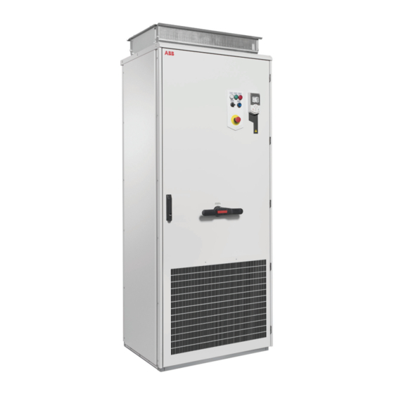
Operation principle and hardware description Contents of this chapter This chapter briefly describes the operation principle and construction of the drive. Product overview The ACS580-07 is an air-cooled cabinet-installed drive for controlling asynchronous AC induction motors and permanent magnet motors. -
Page 32: Single-Line Circuit Diagram Of The Drive
32 Operation principle and hardware description ■ Single-line circuit diagram of the drive R6 R7 R8…R11 In frames R6 and R7: Switch fuse or molded case circuit breaker (option +F289). In frames R8 to R11: Switch-disconnector or molded case circuit breaker (option +F289). Line contactor (option +F250) Auxiliary voltage transformer supplying 24 V and 230/115 V control voltage for, eg, cabinet fan(s), control devices and I/O extension adapter module. -
Page 33: General Information On The Cabinet Layout
Operation principle and hardware description 33 ■ General information on the cabinet layout „ „ IP21 IP42 UL Type 1 UL Type 1 (option +B054) ■ Cabinet layout – R6 and R7 (bottom entry and exit of cables) The cabinet layout of frame R7 with dut/dt filter (option +E205) is shown below. Degree of protection IP42 (option +B054). -
Page 34: Cabinet Layout - R8 And R9 (Bottom Entry And Exit Of Cables)
34 Operation principle and hardware description Cabinet door closed Auxiliary voltage transformer T21 Cabinet door open Motor cable connection terminals Note: For drives with no du/dt filter (option +E205), the motor cables are connected to the drive module terminals. Cabinet door open, mounting plate and cabinet Input cable connection terminals shrouds removed Drive control panel... - Page 35 Operation principle and hardware description 35 Cabinet door closed Auxiliary voltage transformer T21 Cabinet door open Input cable connection terminals Cabinet door open, mounting plates and cabinet Main switch-disconnector (Q1) shrouds removed Drive control panel AC fuses Operating switch Main contactor (Q2, option +F250) Main switch handle Power cable connection terminals of the drive module behind the shroud...
-
Page 36: Mounting Plate - R6 To R9
36 Operation principle and hardware description ■ Mounting plate – R6 to R9 The components and terminals on the mounting plate of frames R6 to R9 are shown below. The layout of frames R6 and R7 is similar. +G300 switch-disconnector and miniature circuit External main contactor control breaker for cabinet heater (option +G300) Emergency stop relay for options +Q951... - Page 37 Operation principle and hardware description 37 X250 Terminals for X250 Auxiliary contacts of line contactor (option +F250) X289 Auxiliary contacts of molded case circuit breaker (op- tion +F289) X951 Push buttons for emergency stop option +Q951 or +Q963. See section Connecting the emergency stop push buttons (options +Q951 and +Q963) (page 109).
-
Page 38: Cabinet Layout - R10 And R11 (Bottom Entry And Exit Of Cables)
38 Operation principle and hardware description ■ Cabinet layout – R10 and R11 (bottom entry and exit of cables) Cabinet door closed Main switch-disconnector Cabinet door open AC fuses Gratings for cooling air out Line contactor (option +F250) Operating switch Lifting lugs Drive control panel Drive control unit... -
Page 39: Mounting Plate
Operation principle and hardware description 39 Cabinet door open, mounting plates and cabinet Input cable connection terminals shrouds removed Power and control cable entries Drive module Motor cable connection terminals Auxiliary voltage transformer T21 Mounting plate The components and terminals on the mounting plate of frames R10 and R11 are shown below. - Page 40 40 Operation principle and hardware description Drive control unit X289 Indication of the status of the molded case circuit breaker (option +F289) Emergency stop relay for options +Q951 X300 Connection terminals for cabinet heater and +Q963 (option +G300) Q95, F95 Switch-disconnector and miniature circuit X951 Connection of external emergency stop...
-
Page 41: Cooling Air Flow
Operation principle and hardware description 41 ■ Cooling air flow The figure below shows cooling air flow in frames R6 to R9 (side view) and in frames R10 and R11 (front view). R6…R9 R10, R11... -
Page 42: Overview Of Power And Control Connections
42 Operation principle and hardware description „ ■ Overview of power and control connections The diagram shows the power connections and control interfaces of the drive. SLOT 1 SLOT 2 M 3 ~ Option slot 1 for optional fieldbus adapter modules Option slot 2 for optional I/O extension modules Embedded fieldbus connector Panel port... -
Page 43: Door Switches And Lights
Operation principle and hardware description 43 ■ Door switches and lights „ Label in English Label in local Description language READY Ready pilot light (option +G327) Run pilot light (option+G328) FAULT Fault pilot light (option +G329) MAIN CONT. Operating switch with option +F250 OFF ON 0 Opens the main contactor (Q2) and disables starting of the drive 1 Closes the main contactor (Q2) -
Page 44: Control By Pc Tools
64). Descriptions of cabinet options Note: All options are not available for all drive types or do not coexist with certain other options. Check actual availability with ABB. ■ Degree of protection Definitions According to IEC/EN 60529, the degree of protection is indicated by an IP code where the first numeral means protection against ingress of solid foreign objects, and the second numeral protection against ingress of water. -
Page 45: Ip21
Operation principle and hardware description 45 IP21 The degree of protection of the standard drive cabinet is IP21 (UL type 1). With doors open, the degree of protection of the standard cabinet and all cabinet options is IP20. The live parts inside the cabinet are protected against contact with clear plastic shrouds or metallic gratings. -
Page 46: Molded Case Circuit Breaker (Mccb, Option +F289)
46 Operation principle and hardware description ■ Molded case circuit breaker (MCCB, option +F289) This option replaces the standard main switch with a molded case circuit breaker. The breaker has inbuilt protection functions against overload and short-circuit. It is operated with a direct rotary handle on the cabinet door. -
Page 47: Type Designation Label
Type designation key The type designation contains information on the specifications and configuration of the drive. The first digits from left express the basic configuration (eg, ACS580-07-0640A-4). The optional selections are given thereafter, separated by plus signs, eg, +B055. The main selections are described below. - Page 48 48 Operation principle and hardware description Code Description Voltage range 380…480 V. This is indicated in the type designation label as typical input voltage level 3~400/480 V AC. Option codes (plus codes) Degree of protection B054 IP42 (UL Type 1) B055 IP54 (UL Type 12) Construction...
- Page 49 Operation principle and hardware description 49 Code Description K458 FSCA-01 RS-485 adapter module K462 FCNA-01 ControlNet™ adapter module K469 FECA EtherCat adapter module K470 FEPL EtherPOWERLINK adapter module K473 FENA-11 Ethernet adapter module for EtherNet/IP™, Modbus TCP and PROFINET IO protocols K490 Ethernet/IP adapter module K491...
-
Page 51: Mechanical Installation
Mechanical installation 51 Mechanical installation Contents of this chapter This chapter describes the mechanical installation procedure of the drive. Examining the installation site Examine the installation site: • The installation site is sufficiently ventilated or cooled to remove heat from the drive. See the technical data. -
Page 52: Necessary Tools
52 Mechanical installation Do not install the drive on an elevated platform or a recess. The module extraction/installation ramp included with the drive is only suitable for a height difference of 50 mm maximum (ie. the standard plinth height of the drive). Necessary tools The tools required for moving the unit to its final position, fastening it to the floor and wall and tightening the connections are listed below:... -
Page 53: Moving And Unpacking The Drive
Mechanical installation 53 Moving and unpacking the drive Move the drive in its original pallet in horizontal position, preferably in the original package to installation site as shown below to avoid damaging the cabinet surfaces and door devices. When you use a pallet truck, check its load capacity before you move the drive. Horizontal package:... - Page 54 54 Mechanical installation Vertical package: 1088 Lifting the transport package with slings. Lifting points Lifting the transport package with forklift...
-
Page 55: Unpacking The Transport Package
Mechanical installation 55 „ ■ Unpacking the transport package This drawing shows the layout of the horizontal transport package. Bracket for attaching the drive to the wooden Timber pallet Cardboard packing hood Drive cabinet Wooden pallet Unpack the horizontal transport package as follows: 1. -
Page 56: Lifting The Cabinet
56 Mechanical installation • option modules (if ordered) installed onto the control unit at the factory • appropriate drive and option module manuals • delivery documents. Check that there are no signs of damage. Before attempting installation and operation, check the information on the type designation labels of the drive to verify that the delivery is of the correct type. -
Page 57: Moving The Cabinet After Unpacking
Mechanical installation 57 „ Lift the cabinet to its position. Maximum allowed angle of the lifting slings is 20° (10° for frames R10 and R11, IP54). ° Max. 10 ° Max. 20 R10, R11 IP54 „ ■ Moving the cabinet after unpacking Move drive cabinet carefully in the upright position. -
Page 58: Final Placement
58 Mechanical installation Final placement Move the cabinet into its final position with an iron bar. Place a wooden piece at the bottom edge of the cabinet in order not to damage the cabinet frame with the iron bar. Attaching the cabinet to the floor and wall or roof „... -
Page 59: Attaching Methods
Mechanical installation 59 Note 1: Make height adjustments before attaching the cabinet with metal shims between the cabinet bottom and the floor. Note 2: If you remove the lifting eyes, attach the bolts back to retain the degree of protection of the cabinet. -
Page 60: Alternative 2 - Using The Holes Inside The Cabinet
■ Arc welding ABB does not recommend attaching the cabinet by arc welding. However, if arc welding is the only option, connect the return conductor of the welding equipment to the cabinet frame at the bottom within 0.5 meters (1’6”) of the welding point. - Page 61 Mechanical installation 61 connected improperly, the welding circuit can damage electronic circuits in the cabinet. WARNING! Do not inhale the welding fumes.
-
Page 63: Guidelines For Planning The Electrical Installation
The installation must always be designed and made according to applicable local laws and regulations. ABB does not assume any liability whatsoever for any installation which breaches the local laws and/or other regulations. Furthermore, if the recommendations given by ABB are not followed, the drive may experience problems that the warranty does not cover. -
Page 64: Examining The Compatibility Of The Motor And Drive
Examining the compatibility of the motor and drive Use asynchronous AC induction motors, permanent magnet synchronous motors, AC induction servomotors or ABB synchronous reluctance motors (SynRM motors) with the drive. Select the motor size and drive type from the rating table on basis of the AC line voltage and motor load. - Page 65 Guidelines for planning the electrical installation 65 This table shows the requirements when an ABB motor is in use. Motor Nominal AC supply Requirement for type voltage Motor insula- ABB du/dt and common mode filters, insulated N-end tion system motor bearings <...
- Page 66 66 Guidelines for planning the electrical installation This table shows the requirements when a non-ABB motor is in use. Motor Nominal AC supply Requirement for type voltage Motor insula- ABB du/dt and common mode filters, insulated N-end tion system motor bearings <...
-
Page 67: Availability Of Du/Dt Filter And Common Mode Filter By Drive Or Inverter Type
If you will use an explosion-safe (EX) motor, follow the rules in the requirements table above. In addition, consult the motor manufacturer for any further requirements. Additional requirements for ABB motors of types other than M2_, M3_, M4_, HX_ and Use the selection criteria given for non-ABB motors. -
Page 68: Additional Data For Calculating The Rise Time And The Peak Line-To-Line Voltage
68 Guidelines for planning the electrical installation If you plan to use a non-ABB high-output motor or an IP23 motor, consider these additional requirements for protecting the motor insulation and bearings in drive systems: • If motor power is below 350 kW: Equip the drive and/or motor with the filters and/or bearings according to the table below. -
Page 69: Additional Note For Common Mode Filters
Guidelines for planning the electrical installation 69 Û du/dt ------------ - (1/Ps) l (m) du/dt ------------ - (1/Ps) Û l (m) Drive with du/dt filter Drive without du/dt filter Motor cable length Û Relative peak line-to-line voltage (du/dt)/U Relative du/dt value Additional note for common mode filters Common mode filters are available as plus code option +E208. -
Page 70: Typical Power Cable Sizes
70 Guidelines for planning the electrical installation To comply with the EMC requirements of the CE mark, use one of the preferred cable types. Preferred power cable types (page 71). Symmetrical shielded cable reduces electromagnetic emission of the whole drive system as well as the stress on motor insulation, bearing currents and wear. -
Page 71: Power Cable Types
Guidelines for planning the electrical installation 71 ■ Power cable types Preferred power cable types This section presents the preferred cable types. Check with local/state/country electrical codes for allowance. Cable type Use as input power cabling Use as motor cabling Symmetrical shielded (or armored) cable with three phase conductors and concentric PE conductor as... -
Page 72: Not Allowed Power Cable Types
■ Additional guidelines, North America ABB recommends the use of conduit for power wiring to the drive and between the drive and the motor(s). Due to the variety of application needs, metallic and non-metallic conduit can be used. ABB prefers the use of metallic conduit. -
Page 73: Metal Conduit
Guidelines for planning the electrical installation 73 Wiring method Notes Free air Enclosures, air handlers, etc. • Allowed internally in enclosures when in accordance with UL. 1) Metallic conduit may be used as an additional ground path, provided this path is a solid path capable of handling ground currents. -
Page 74: Signals In Separate Cables
■ Relay cable type The cable type with braided metallic screen (for example ÖLFLEX by LAPPKABEL, Germany) has been tested and approved by ABB. ■ Control panel to drive connection Use EIA-485 with male RJ-45 connector, cable type Cat 5e or better. The maximum permitted... -
Page 75: Routing The Cables
Guidelines for planning the electrical installation 75 Routing the cables ■ General guidelines – IEC • Route the motor cable away from other cables. Motor cables of several drives can be run in parallel installed next to each other. • Install the motor cable, input power cable and control cables on separate trays. -
Page 76: General Guidelines - North America
76 Guidelines for planning the electrical installation ■ General guidelines – North America Make sure that the installation is in accordance with national and local codes. Obey these general guidelines: • Use separate conduits for the input power, motor, brake resistor (optional), and control cabling. -
Page 77: Continuous Motor Cable Shield/Conduit Or Enclosure For Equipment On The Motor Cable
Guidelines for planning the electrical installation 77 ■ Continuous motor cable shield/conduit or enclosure for equipment on the motor cable To minimize the emission level when safety switches, contactors, connection boxes or similar equipment are installed on the motor cable between the drive and the motor: •... -
Page 78: Protecting The Motor Against Thermal Overload
78 Guidelines for planning the electrical installation WARNING! If the drive is connected to multiple motors, use a separate circuit breaker or fuses for protecting each motor cable and motor against overload. The drive overload protection is tuned for the total motor load. It may not trip due to an overload in one motor circuit only. -
Page 79: Using Power Factor Compensation Capacitors With The Drive
■ Implementing a safety switch between the drive and the motor ABB recommends that you install a safety switch between the permanent magnet motor and the drive output. The switch is needed to isolate the motor during any maintenance work on the drive. -
Page 80: Implementing A Bypass Connection
IEC/EN 61800-5-1, subclause 6.5.3, for example, “THIS MACHINE STARTS AUTOMATICALLY”. Bypass connection is available as a factory-installed option for some cabinet-installed drive types. Consult ABB for more information. WARNING! Never connect the drive output to the electrical power network. The connection may damage the drive. -
Page 81: Connecting Motor Temperature Sensor To The Drive Via An Option Module
Guidelines for planning the electrical installation 81 230 V AC 230 V AC + 24 V DC Relay output Varistor RC filter Diode ■ Connecting motor temperature sensor to the drive via an option module This table shows: • the option module types that you can use for the motor temperature sensor connection •... -
Page 82: Protecting The Drive Against Ground Faults
See the user’s manual for the wiring, start-up and operation instructions. Option User’s manual Manual code (English) code +Q951 Emergency stop, stop category 0 (option +Q951) for ACS580-07, 3AXD50000171828 ACH580-07 and ACQ580-07 drives user's manual +Q963 Emergency Stop, Category 0 (option +Q963) without opening main 3AXD50000171835... -
Page 83: Implementing The Power-Loss Ride-Through Function
Implementing a safety switch between the drive and the motor ABB recommends to install a safety switch between the permanent magnet synchronous motor and the drive output. The switch is needed to isolate the motor during any maintenance work on the drive. -
Page 84: Using A Contactor Between The Drive And The Motor
Inductive loads (relays, contactors, motors) cause voltage transients when switched off. ABB highly recommends to equip inductive loads with noise attenuating circuits (varistors, RC filters [AC] or diodes [DC]) in order to minimize the EMC emission at switch-off. If not suppressed, the disturbances can connect capacitively or inductively to other conductors in the control cable and form a risk of malfunction in other parts of the system. -
Page 85: Implementing A Motor Temperature Sensor Connection
Guidelines for planning the electrical installation 85 230 V AC 230 V AC + 24 V DC 1) Relay outputs; 2) Varistor; 3) RC filter; 4) diode Implementing a motor temperature sensor connection WARNING! IEC 60664 requires double or reinforced insulation between live parts and the surface of accessible parts of electrical equipment which are either non-conductive or conductive but not connected to the protective earth. - Page 86 86 Guidelines for planning the electrical installation This table shows what temperature sensor types you can connect to the drive I/O extension modules as well as the insulation requirement for the sensor. Extension module Temperature sensor type Type Insulation Pt100, Pt1000 CMOD-02 Reinforced insulation between the sensor connector and the other connectors of the...
-
Page 87: Electrical Installation
Electrical installation 87 Electrical installation Contents of this chapter This chapter gives instructions on the wiring the drive. Warnings WARNING! If you are not a qualified electrician do not do the installation work described in this chapter. Obey the instructions in chapter Safety instructions. -
Page 88: Layout Of The Cable Entries (Frames R6 To R9)
88 Electrical installation Layout of the cable entries (frames R6 to R9) The layout of the input and motor cable connection terminals of frame R9 without du/dt filter (option +E205) is shown below. The shrouds in front of the terminals are removed. The layout is similar for the other frame sizes. -
Page 89: Layout Of The Cable Entries (Frames R10 And R11)
Electrical installation 89 Layout of the cable entries (frames R10 and R11) The layout of the input and motor cable connection terminals of frame R10 is shown below. The shrouds in front of the terminals are removed. The layout is similar for frame R11. L1, L2, L3 Input power cable terminals U2, V2, W2... -
Page 90: Connecting The Power Cables
90 Electrical installation Connecting the power cables „ ■ Connection diagram T1/ T2/ T3/ (PE) (PE) Use a separate grounding PE cable (1a) or a cable with a separate PE conductor (1b) if the conductivity of the shield does not meet the requirements for the PE conductor. 360-degree grounding is recommended if shielded cable is used. -
Page 91: Checking The Insulation Of The Drive System
Electrical installation 91 ■ Checking the insulation of the drive system WARNING! Do not make any voltage withstand or insulation resistance tests on any part of the drive as testing can damage the drive. Every drive has been tested for insulation between the main circuit and the chassis at the factory. -
Page 92: Guidelines For Installing The Drive To A Tt System
92 Electrical installation Frame Symmetrically grounded TN Corner-grounded (B1) and IT systems (ungrounded or size systems (TN-S systems), ie. midpoint-grounded delta (B2) high-resistance grounded [>30 center-grounded wye (A) systems ohms]) (C) Drive Drive Drive Drive These are the EMC filter and varistor screws in different drive frame sizes. Frame EMC filter (+E200) screws Ground-to-phase varistor screws... -
Page 93: Identifying Different Types Of Electrical Power Systems
Because the varistor wire has been disconnected, ABB does not guarantee the EMC category. • ABB does not guarantee the functioning of the ground leakage detector built inside the drive. • In large systems the residual current device can trip without a real reason. -
Page 94: Disconnecting The Emc Filter And Ground-To-Phase Varistor (R6 To R9)
94 Electrical installation Electrical power system type Connection diagram L1-G L2-G L3-G 0.866·X 0.5·X 0.5·X Midpoint-grounded delta system (nonsymmetrical) Varying Varying Varying IT systems (ungrounded or high- level versus level versus level versus resistance-grounded [>30 ohms]) time time time nonsymmetrical Disconnecting the EMC filter and ground-to-phase varistor (R6 to R9) To disconnect the internal EMC filter or ground-to-phase varistor, do as follows: 1. - Page 95 Electrical installation 95...
-
Page 96: Connecting The Motor Cable At The Motor End
Use a measuring voltage of 1000 V DC. The insulation resistance of an ABB motor must exceed 100 Mohm (reference value at 25 °C [77 °F]). For the insulation resistance of other motors, consult the manufacturer’s instructions. - Page 97 Electrical installation 97 • contactor feedback connector X250 with option +F250 • cabinet door fan supply connector X8 and control X505 • cabinet heater connector X300 with option +G300. 4. For drives without option +E205: Remove the shrouds (4a, 4b, 4c and 4d). To remove the shroud on the power cable terminals, release the clips with a screwdriver and pull the shroud out (4d).
- Page 98 12. Seal the slot between the cable and mineral wool sheet (if used) with sealing compound (eg, CSD-F, ABB brand name DXXT-11, code 35080082). 13. Connect the twisted shields of the motor cables to the ground bar and the phase...
- Page 99 Electrical installation 99 filter (option +E205), connect the phase conductors to the T1/U2, T2/V2 and T3/W2 terminals of the cabinet with cable lugs. 14. Connect the twisted shields of the input cables and separate ground cable (if present) to the PE terminal of the cabinet and the phase conductors to the L1, L2 and L3 terminals. 15.
-
Page 100: Connection Procedure (Iec, Frames R10 And R11)
100 Electrical installation ■ Connection procedure (IEC, frames R10 and R11) 1. Do the steps in section Electrical safety precautions (page 20) before you start the work. 2. Open the cabinet door. 3. Remove the shrouding: • With bottom entry and bottom exit: Undo the mounting screws and pull the shroud out. - Page 101 Electrical installation 101...
- Page 102 102 Electrical installation • With top entry and top exit (options +H351 and +H353): Remove the shrouds and door fan (see Replacing the door fan (frames R10 and R11) (page 141)). Undo the mounting screws and pull the shrouds out. 4.
- Page 103 10. Attach the conductive sleeves to the cable shields with cable ties. Tie up the unused conductive sleeves with cable ties. 11. Seal the slot between the cable and mineral wool sheet (if used) with sealing compound (eg, CSD-F, ABB brand name DXXT-11, code 35080082).
-
Page 104: Connecting The Control Cables
104 Electrical installation 12. Connect the twisted shields of the motor cables to the ground bar and the phase conductors to the U2, V2 and W2 terminals of the drive module. 13. Connect the twisted shields of the input cables and separate ground cable (if present) to the PE terminal of the cabinet and the phase conductors to the L1, L2 and L3 terminals. -
Page 105: Grounding The Outer Shields Of The Control Cables At The Cabinet Entry
Electrical installation 105 • Connecting external power supply wires for the cabinet heater (option +G300) (page 110) ■ Grounding the outer shields of the control cables at the cabinet entry Ground the outer shields of all control cables 360 degrees at the EMI conductive cushions as follows (example constructions are shown below, the actual hardware may vary): 1. - Page 106 106 Electrical installation Stripped cable Conductive surface of the shield exposed Stripped part covered with copper foil Cable shield Copper foil Shielded twisted pair Grounding wire Note for top entry of cables: When each cable has its own rubber grommet, sufficient IP and EMC protection can be achieved.
-
Page 107: Routing The Control Cables Inside The Cabinet
Electrical installation 107 ■ Routing the control cables inside the cabinet The route of the control cables is shown below in frame R9. The route is similar frames R6, R7 and R8. X504 (+L504) The route of the control cables for frames R10 and R11 is shown below. -
Page 108: Connecting External Wiring To The Control Unit Or Optional I/O Terminal Block
108 Electrical installation X504 (+L504) ■ Connecting external wiring to the control unit or optional I/O terminal block Note: Keep any signal wire pairs twisted as close to the terminals as possible. Twisting the wire with its return wire reduces disturbances caused by inductive coupling. Note: Leave slack to the control wires to make it possible to lift the control unit mounting plate a little when the drive module is replaced. -
Page 109: Connecting The Emergency Stop Push Buttons (Options +Q951 And +Q963)
Electrical installation 109 Leave the other ends of the control cable shields unconnected or ground them indirectly via a high-frequency capacitor with a few nanofarads, eg, 3.3 nF / 630 V. The shield can also be grounded directly at both ends if they are in the same ground line with no significant voltage drop between the end points. -
Page 110: Connecting External Power Supply Wires For The Cabinet Heater (Option +G300)
110 Electrical installation * Remove bridges 1–2 and 3–4 if there is an external Internal Customer X969 Safe torque off function connections connections STO OUT1 STO OUT1 STO IN1 STO IN1 STO IN2 STO IN2 STO OUT2 STO OUT2 STO INTERNAL „... -
Page 111: Setting The Voltage Range Of The Auxiliary Control Voltage Transformer (T21)
Electrical installation 111 Setting the voltage range of the auxiliary control voltage transformer (T21) Connect the power supply wires of the auxiliary control voltage transformer according to the power network voltage. Connecting a PC A PC (with eg, the Drive composer PC tool) can be connected as follows: 1. -
Page 112: Installing Option Modules
112 Electrical installation Installing option modules WARNING! Obey the instructions in chapter Safety instructions. If you ignore them, injury or death, or damage to the equipment can occur. 1. Stop the drive and do the steps in section Electrical safety precautions (page 20) before you start the work. -
Page 113: Option Slot 1 (Fieldbus Adapter Modules)
Electrical installation 113 ■ Option slot 1 (fieldbus adapter modules) 1. Put the module carefully into its position on the control unit. 2. Tighten the mounting screw (CHASSIS) to 0.8 N·m. The screw tightens the connections and grounds the module. It is necessary for fulfilling the EMC requirements and for correct operation of the module. -
Page 115: Control Unit
Control unit 115 Control unit Contents of this chapter This chapter contains the default I/O connection diagram, descriptions of the terminals and technical data for the drive control unit (CCU-24). Layout The layout of the external control connection terminals on the drive module control unit is shown below. - Page 116 116 Control unit SLOT 1 SLOT 1 Option slot 1 (fieldbus adapter modules) ANALOG IN/OUT 1...3 Analog input 1 1…3, AI1 Current/Voltage selection switch analog input 1 4…6, AI2 4...6 Analog input 2 7…9, AO1 Current/Voltage selection switch for analog input 2 10…12 7...9 Analog outputs...
-
Page 117: Default I/O Connection Diagram
Control unit 117 Default I/O connection diagram The default I/O connections of the ABB Standard macro are shown below. Reference voltage and analog inputs and outputs Signal cable shield (screen) Output frequency reference: 0…10 V 1…10 kohm AGND Analog input circuit common... -
Page 118: Option +E205 In Frames R10 And R11: Di6 Internal Overtemperature Supervision
118 Control unit 2. Total load capacity of the Auxiliary voltage output +24V (X2:10) is 6.0 W (250 mA / 24 V) minus the power taken by the option modules installed on the board. 3. In scalar control (default): See Menu - Primary settings - Start, stop, reference - Constant frequencies or parameter group 28 Frequency reference chain. -
Page 119: Power Supply Connections For Npn With Option +L504
Control unit 119 Internal +24 V power supply External +24 V power supply PNP connection (source) PNP connection (source) X503:1 X503:1 +24V +24V DGND DGND 0 V DC DCOM DCOM +24 V DC X504:18 X504:18 Power supply connections for NPN with option +L504 Internal and external +24 V power supply connections for NPN configuration are shown below. -
Page 120: Changing Internal Overtemperature Supervision From Di6 To Another Digital Input
120 Control unit Internal +24 V power supply External +24 V power supply NPN connection (sink) NPN connection (sink) +24V +24V DGND DGND +24 V DC DCOM DCOM 0 V DC Changing internal overtemperature supervision from DI6 to another digital input With option +E205 in frames R10 and R11, by default, digital input DI6 is used for the internal overtemperature supervision of the drive cabinet. -
Page 121: Npn Configuration For Digital Inputs (X2 & X3)
Control unit 121 Internal +24 V power supply External +24 V power supply PNP connection (source) PNP connection (source) X2 & X3 X2 & X3 +24V +24V +24 V DC DGND DGND 0 V DC DCOM DCOM WARNING! Do not connect the +24 V AC cable to the control unit ground when the control unit is powered from an external 24 V AC supply. -
Page 122: Connection Examples Of Two-Wire And Three-Wire Sensors To Analog Input (Ai2)
122 Control unit 8 AO2 Analog output 2. Default output 0…20 mA. 500 ohm Analog common ground. Internally connected to chassis 9 AGND through a 2 Mohm resistor. 8 AO2 Analog output 2. Default output 0…20 mA. 1 kohm 1 kohm Analog common ground. -
Page 123: Ai1 And Ai2 As Pt100, Pt1000, Ni1000, Kty83 And Kty84 Sensor Inputs (X1)
Control unit 123 "0" > kohm "1" < 1.5 kohm = 5 mA ■ AI1 and AI2 as Pt100, Pt1000, Ni1000, KTY83 and KTY84 sensor inputs (X1) One, two or three Pt100 sensors; one, two or three Pt1000 sensors; or one Ni1000, KTY83 or KTY84 sensor for motor temperature measurement can be connected between an analog input and output as shown below. - Page 124 124 Control unit Note: Only 24 V DC can be used for STO. Only PNP input configuration can be used.
-
Page 125: Technical Data
Control unit 125 Technical data External power supply Maximum power: 36 W, 1.50 A at 24 V AC/DC ±10% as standard Term. 40, 41 Terminal size: 0.14…2.5 mm +24 V DC output Total load capacity of this outputs is 6.0 W (250 mA / 24 V) minus the power taken by the option modules installed on board. - Page 126 126 Control unit Safe torque off (STO) inputs 24 V DC logic levels: "0" < 5 V, "1" > 13 V IN1 and IN2 (Term. 37 and 38) : 2.47 kohm Terminal size: 0.14…2.5 mm Embedded fieldbus (X5) Connector pitch 5 mm, wire size 2.5 mm Physical layer: EIA-485 Cable type: Shielded twisted pair cable with twisted pair for data and a wire or pair for signal ground, nominal impedance 100…165 ohms, for example...
- Page 127 Control unit 127 Ground isolation diagram Slot 1 Slot 2 AGND +10V AGND AGND X2 & X3 +24V DGND DCOM X6, X7, X8 RO1C RO1A RO1B RO2C RO2A RO2B RO3C RO3A RO3B DGND OUT1 OUT2 SGND 24VAC/DC+in 24VAC/DC-in Ground Jumper installed at factory...
-
Page 129: Installation Checklist Of The Drive
Installation checklist of the drive 129 Installation checklist of the drive Contents of this chapter This chapter contains a checklist of the mechanical and electrical installation of the drive. Checklist Examine the mechanical and electrical installation of the drive before start-up. Go through the checklist together with another person. - Page 130 130 Installation checklist of the drive Make sure that … There is an adequately sized protective earth (ground) conductor between the drive and the switchboard, the conductor has been connected to appropriate terminal, and the terminal has been tightened to the proper torque.
-
Page 131: Start-Up
Start-up 131 Start-up Contents of this chapter This chapter contains the start-up procedure of the drive. The default device designations (if any) are given in brackets after the name, for example "main switch-disconnector (Q1)". The same device designations are also used in the circuit diagrams, typically. Start-up procedure Action Safety... - Page 132 132 Start-up Action Setup the drive control program. See Quick start-up guide for ACS580 drives with standard control program (3AXD50000048035 [English]) Drives with main contactor (Q2, option +F250): Close the main contactor by turning the operating switch on the cabinet door from OFF into ON position. Perform the first start of the drive and motor.
-
Page 133: Fault Tracing
Fault tracing 133 Fault tracing Contents of this chapter This chapter describes the fault tracing possibilities of the drive. Warning and fault messages See the firmware manual for the descriptions, causes and remedies of the drive control program warning and fault messages. -
Page 135: Maintenance
(www.abb.com/drivesservices).For more information, consult your local ABB Service representative (www.abb.com/searchchannels). The maintenance and component replacement intervals are based on the assumption that the equipment is operated within the specified ratings and ambient conditions. ABB recommends annual drive inspections to ensure the highest reliability and optimum performance. -
Page 136: Recommended Annual Maintenance Actions By The User
136 Maintenance ■ Recommended annual maintenance actions by the user. Action Target IP42 air inlet and outlet meshes on the cabinet doors IP54 air filters on the cabinet doors Quality of supply voltage Spare parts Capacitor reforming, spare modules and spare capacitors Tightness of terminals Dustiness, corrosion or temperature Heat sink cleaning... -
Page 137: Cleaning The Air Inlet (Door) Meshes (Ip42 / Ul Type 1 Filtered)
Maintenance 137 3. Check the air inlet and outlet meshes/filters of the cabinet. Clean when necessary. For IP42 (UL Type 1 Filtered) drives: see section Cleaning the air inlet (door) meshes (IP42 / UL Type 1 Filtered) below. For IP54 (UL Type 12) drives: see section Cleaning the air inlet (door) meshes (IP42 / UL Type 1 Filtered). -
Page 138: Outlet (Roof) Filters (Ip54 / Ul Type 12)
138 Maintenance ■ Outlet (roof) filters (IP54 / UL Type 12) 1. Remove the front and back gratings of the fan cubicle by lifting them upwards 2. Remove the air filter mat. 3. Place the new filter mat in the grating. 4. -
Page 139: Fans
Reset the running time signal after fan replacement. Replacement fans are available from ABB. Do not use other than ABB specified spare parts. ■ Replacing the door fan (frames R6 to R9) Applicability: For drives with option +F250, +L537, +B055, +Q951, +Q963, Q971 or +G300. -
Page 140: Replacing The Cabinet Fan (Frames R6 To R9)
140 Maintenance ■ Replacing the cabinet fan (frames R6 to R9) Applicability: For drives without any of these options +F250, +L537, +B055, +Q951, +Q963, +Q971 and +G300 WARNING! Obey the instructions in chapter Safety instructions. If you ignore them, injury or death, or damage to the equipment can occur. -
Page 141: Replacing The Door Fan (Frames R10 And R11)
Maintenance 141 ■ Replacing the door fan (frames R10 and R11) WARNING! Obey the instructions in chapter Safety instructions. If you ignore them, injury or death, or damage to the equipment can occur. 1. Stop the drive and do the steps in section Electrical safety precautions (page 20) before you start the work. - Page 142 142 Maintenance...
-
Page 143: Replacing The Cabinet Fan (Frames R10 And R11, Ip54)
Maintenance 143 ■ Replacing the cabinet fan (frames R10 and R11, IP54) WARNING! Obey the instructions in chapter Safety instructions. If you ignore them, injury or death, or damage to the equipment can occur. 1. Stop the drive and do the steps in section Electrical safety precautions (page 20) before you start the work. -
Page 144: Replacing The Drive Module Main Fans (Frames R6 To R8)
144 Maintenance ■ Replacing the drive module main fans (frames R6 to R8) WARNING! Obey the instructions in chapter Safety instructions. If you ignore them, injury or death, or damage to the equipment can occur. 1. Stop the drive and do the steps in section Electrical safety precautions (page 20) before you start the work. -
Page 145: Replacing The Drive Module Main Fans (Frame R9)
Maintenance 145 10. Install the new fan in reverse order. 11. Reset the fan on-time counter in parameter group 5 of the drive control program. ■ Replacing the drive module main fans (frame R9) WARNING! Obey the instructions in chapter Safety instructions. -
Page 146: Replacing The Drive Module Main Fans (Frames R10 And R11)
146 Maintenance ■ Replacing the drive module main fans (frames R10 and R11) WARNING! Obey the instructions in chapter Safety instructions. If you ignore them, injury or death, or damage to the equipment can occur. 1. Stop the drive and do the steps in section Electrical safety precautions (page 20) before you start the work. -
Page 147: Replacing The Auxiliary Cooling Fan Of The Drive Module (Frames R6 To R9)
Maintenance 147 ■ Replacing the auxiliary cooling fan of the drive module (frames R6 to WARNING! Obey the instructions in chapter Safety instructions. If you ignore them, injury or death, or damage to the equipment can occur. 1. Stop the drive and do the steps in section Electrical safety precautions (page 20) before you start the work. -
Page 148: Replacing The Drive Module (Frames R6 To R9)
148 Maintenance Replacing the drive module (frames R6 to R9) This replacing procedure requires: preferably two persons, a set of screw drivers with extension bar and a torque wrench, chains for securing the module during the installation. The drawings below show a cabinet of frame size R7. The procedure is the same for the other frame sizes. - Page 149 Maintenance 149 Tap screw M6x16 T30 (hex) Torx M6x16 Torx M6x16 Torx M6x16 4. Unplug the wires connected to the mounting plate connectors (if present). 5. Remove the mounting plate (four screws). 6. Remove the shroud (two screws). 7. Remove the shroud on the power cable connection terminals.
- Page 150 150 Maintenance 8. Disconnect the option modules from the control unit. 9. For drives with additional I/O terminal block (option +L504), disconnect the upper terminals and remove any fastening. Move the wires aside before you lift the module out. Note: Mark the wires for reconnection!
- Page 151 Maintenance 151 10. For drives without additional I/O terminal block (option +L504), disconnect the customer-installed wires from the control unit. Note: Mark the wires for reconnection! 11. For drives with line contactor (option +F250), disconnect the input power cables from the output of the contactor.
- Page 152 152 Maintenance 13. Secure the drive module with chains from the lifting eyes. 14. Undo the mounting screws of the flange. 15. Slide the drive module forwards along the sliding bars. 16. Lift the module out of the cabinet with a lifting device.
- Page 153 Maintenance 153 17. Remove the flange. Combiscrew M6×25 T25 M6 nut, 6 N·m M6 nut, 6 N·m M6×10 T30, 6 N·m 18. Install the new module in reverse order.
-
Page 154: Replacing The Drive Module (Frames R10 And R11)
154 Maintenance Replacing the drive module (frames R10 and R11) WARNING! Obey the instructions in chapter Safety instructions. If you ignore them, injury or death, or damage to the equipment can occur. This replacing procedure requires: preferably two persons, installation ramp, a set of screw drivers and a torque wrench with an extension bar of 500 mm (20 in), chains for securing the module during the installation. - Page 155 Maintenance 155...
- Page 156 156 Maintenance 7. Disconnect the drive module input busbars with a torque wrench withn an extension bar of 500 mm (20 in). Combi screw M12, 70 N·m (52 lbf·ft).
- Page 157 Maintenance 157 8. Disconnect the drive module output busbars. M12, 70 N·m (52 lbf·ft).
- Page 158 158 Maintenance 9. Remove the shroud. Undo the screws that attach the drive module to the cabinet at the top and behind the front support legs.
- Page 159 Maintenance 159 10. Attach the extraction ramp to the cabinet base with two screws. 11. Attach the drive module lifting lugs to the cabinet lifting lug with chains. 12. Pull the drive module carefully out of the cabinet preferably with help from another person.
-
Page 160: Replacing The Drive Module (Frames R10 And R11, Ip54)
160 Maintenance 13. Install the new module in reverse order. Replacing the drive module (frames R10 and R11, IP54) WARNING! Obey the instructions in chapter Safety instructions. If you ignore them, injury or death, or damage to the equipment can occur. This replacing procedure requires: preferably two persons, installation ramp, a set of screw drivers and a torque wrench with an extension bar of 500 mm (20 in), chains for securing the module during the installation. - Page 161 Maintenance 161...
- Page 162 162 Maintenance 7. Disconnect the drive module input busbars with a torque wrench withn an extension bar of 500 mm (20 in). Combi screw M12, 70 N·m (52 lbf·ft).
- Page 163 Maintenance 163 8. Disconnect the drive module output busbars. M12, 70 N·m (52 lbf·ft).
- Page 164 164 Maintenance 9. Remove the shroud. Undo the screws that attach the drive module to the cabinet at the top and behind the front support legs.
- Page 165 Maintenance 165 10. Attach the extraction ramp to the cabinet base with two screws. 11. Attach the drive module lifting lugs to the cabinet lifting lug with chains. 12. Pull the drive module carefully out of the cabinet preferably with help from another person.
-
Page 166: Capacitors
Capacitor failure is usually followed by damage to the unit and an input cable fuse failure, or a fault trip. Contact ABB if capacitor failure is suspected. Replacements are available from ABB. Do not use other than ABB specified spare parts. Contact an ABB service representative for spare parts and repair services. -
Page 167: Replacing Ac Fuses
Maintenance 167 1. Stop the drive and do the steps in section Electrical safety precautions (page 20) before you start the work. 2. Open the cabinet door. 3. Remove the shrouding from in front of the switch fuse. 4. Replace the fuses with the fuse handle which is in the cabinet. 5. -
Page 168: Control Panel
168 Maintenance Control panel ■ Cleaning the control panel Use a soft damp cloth to clean the control panel. Avoid harsh cleaners which could scratch the display window. ■ Replacing the battery in the assistant control panel A battery is only used in assistant control panels that have the clock function. The battery keeps the clock operating during power interruptions. - Page 169 Maintenance 169 CR2032...
-
Page 171: Technical Data
The nominal ratings for the drives with 50 Hz and 60 Hz supply are given below. The symbols are described in section Definitions (page 173). IEC RATINGS Drive type Frame Input Output ratings ACS580-07- size rating No-overload use Light-overload Heavy-overload = 400 V 0145A-4 0169A-4... -
Page 172: Nec Ratings
172 Technical data IEC RATINGS Drive type Frame Input Output ratings ACS580-07- size rating No-overload use Light-overload Heavy-overload 0650A-4 0725A-4 1020 0820A-4 1020 0880A-4 1100 725*** 3AXD10000451709 NEMA RATINGS Drive type Frame Input rat- Max. cur- App. Output ratings ACS580-07-... -
Page 173: Definitions
Note 2: To achieve the rated motor power given in the table, the rated current of the drive must be higher than or equal to the rated motor current. The DriveSize dimensioning tool available from ABB is recommended for selecting the drive, motor and gear combination. -
Page 174: Drive Types Acs580-0414A-4 And Acs580-0430A-4
„ „ 174 Technical data 1.00 0.90 0.80 +40 °C +50 °C +104 °F +122 °F For example: Temperature Derated current 40 ºC (104 ºF) 45 ºC (113 ºF) 0.95 · I 0.95 · I 50 ºC (122 ºF) 0.90 · I 0.90 ·... -
Page 175: Deratings For Special Settings In The Drive Control Program
Technical data 175 Frame Coeffficient 1000 m 2000 m 3000 m 4000 m 3281 ft 6562 9842 ft 13123 ft 1.00 0.90 0.80 0.70 If ambient temperature is below +40 °C (+104 .°F), the derating can be reduced by 1.5% for every 1 °C reduction in temperature. -
Page 176: Fuses (Iec)
Changing the value of parameter 97.01 Switching frequency reference does not require derating. Fuses (IEC) The standard drive is equipped with aR fuses listed below. Drive type Input cur- Ultrarapid (aR) fuses (one fuse per phase) ACS580-07- rent Type Type Size (Buss- (Mersen) -
Page 177: Fuses (Ul)
The drive also requires external fuses for branch circuit protection per NEC, see section Fuses for branch circuit protection (page 178). Drive type Input Fuse (one fuse per phase) ACS580-07- current Type Type Type with op- Size class / tion +F289... -
Page 178: Fuses For Branch Circuit Protection
The drive also requires external fuses for branch circuit protection per NEC, see section Fuses for branch circuit protection (page 178). Drive type Input current Fuse (one fuse per phase) with option +F289 ACS580-07- Manufacturer Type Size = 480 V 0145A-4 Bussmann... -
Page 179: Dimensions And Weights
Technical data 179 Drive type Input Fuse (one fuse per phase) NEC type current ACS580-07- Manufacturer Type class 0505A-4 Bussmann JJS-600 0585A-4 Ferraz A4BY800 0650A-4 Ferraz A4BY800 0725A-4 Ferraz A4BY800 0820A-4 Ferraz A4BY900 0880A-4 1000 Ferraz A4BY1000 Note 1: See also Implementing the emergency stop function (page 82). -
Page 180: Maximum Allowed Plinth Height For The Extraction/Installation Ramp
For the cable sizes accepted by the drive cabinet cable entries and connection terminals, see Terminal and entry data for the power cables (page 182). Drive type ACS580-07- Frame size Cu cable type Al cable type... -
Page 181: Losses, Cooling Data And Noise
Technical data 181 Drive type ACS580-07- Frame size Cu cable type Al cable type Cu cable type AWG/kcmil per phase 0156A-4 3x120 3x150 250 MCM 0180A-4 3x150 3x240 300 MCM 0240A-4 2x(3x70) 2x(3x95) 2x2/0 0260A-4 2x(3x95) 2x(3x120) 2x3/0 0361A-4 2x(3x120) -
Page 182: Terminal And Entry Data For The Power Cables
182 Technical data Terminal and entry data for the power cables There are two (in frames R6 to R9) or four (in frames R10 and R11) 60 mm (2.36 in) diameter holes in the entry plate for the input power cables and two (in frames R6 to R9) or four (in frames R10 and R11) 60 mm (2.36 in) diameter holes for the motor cables. -
Page 183: Us - With Option +E205
Technical data 183 Frame L1, L2, L3 T1/U2, T2/V2, T3/W2 PE (grounding) size Max. wire Bolt size Tighten- Min. wire Max. wire Tighten- Bolt size Tighten- size ing torque size size ing torque ing torque lbf·ft lbf·ft lbf·ft 3×300 M10 (3/8") 22.1 3×300 22.1... -
Page 184: Connection Drawings
184 Technical data Connection drawings „ Frame R6: Input and motor cable terminal dimensions (bottom entry and exit, switch fuse OS250) DET A... - Page 185 Technical data 185 Frame R6: Input and motor cable terminal dimensions (bottom entry and exit, switch fuse OS400) DET A...
- Page 186 186 Technical data Frame R6: Input and motor cable terminal dimensions (option +F289) DET A...
- Page 187 Technical data 187 Frames R6 and R7: Input and motor cable terminal dimensions (bottom entry and exit, switch fuse OS250, du/dt filter [option +E205])
- Page 188 188 Technical data Frames R6 and R7: Input and motor cable terminal dimensions (bottom entry and exit, switch fuse OS400, du/dt filter [option +E205])
- Page 189 Technical data 189 Frames R6 and R7: Input and motor cable terminal dimensions (bottom entry and exit, options +F289 and +E205)
- Page 190 190 Technical data Frame R7: Input and motor cable terminal dimensions (bottom entry and exit, switch fuse OS250) DET A...
- Page 191 Technical data 191 Frame R7: Input and motor cable terminal dimensions (bottom entry and exit, switch fuse OS400) DET A...
- Page 192 192 Technical data Frame R7: Input and motor cable terminal dimensions (bottom entry and exit, option +F289)
- Page 193 Technical data 193 Frames R6 and R7: Input and motor cable terminal dimensions (top entry and exit, options +H351 and +H353)
- Page 194 194 Technical data Frame R8: Input and motor cable terminal dimensions (bottom entry and exit, switch-disconnector OT400) DET A...
- Page 195 Technical data 195 Frame R8: Input and motor cable terminal dimensions (bottom entry and exit, switch-disconnector OT400, du/dt filter [option +E205])
- Page 196 196 Technical data Frame R8: Input and motor cable terminal dimensions (bottom entry and exit, option +F289)
- Page 197 Technical data 197 Frame R9: Input and motor cable terminal dimensions (bottom entry and exit, switch-disconnector OT630) DET A...
- Page 198 198 Technical data Frame R9: Input and motor cable terminal dimensions (bottom entry and exit, switch-disconnector OT630, du/dt filter [option +E205])
- Page 199 Technical data 199 Frames R8 and R9: Input and motor cable terminal dimensions (top entry and exit, options +H351 and +H353)
- Page 200 200 Technical data Frames R8 and R9: Input and motor cable terminal dimensions (bottom entry and exit, options +F289 and +E205)
- Page 201 Technical data 201 Frame R9: Input and motor cable terminal dimensions (option +F289)
- Page 202 202 Technical data Frame R10: Input and motor cable terminal dimensions (bottom entry and exit)
- Page 203 Technical data 203 Frame R10: Input and motor cable terminal dimensions (bottom entry and exit, option +E205)
- Page 204 204 Technical data Frame R10: Input and motor cable terminal dimensions (top entry and exit)
- Page 205 Technical data 205 Frame R10: Input and motor cable terminal dimensions (top entry and exit, option +F289)
- Page 206 206 Technical data Frame R11: Input and motor cable terminal dimensions (bottom entry and exit)
- Page 207 Technical data 207 Frame R11: Input and motor cable terminal dimensions (bottom entry and exit, option +E205)
- Page 208 208 Technical data Frame R11: Input and motor cable terminal dimensions (top entry and exit)
- Page 209 Technical data 209 Frame R11: Input and motor cable terminal dimensions (top entry and exit, option +F289)
-
Page 210: Terminal And Connection Data For Auxiliary Control Circuits
210 Technical data Terminal and connection data for auxiliary control circuits Maximum acceptable voltage and current values and wire sizes in terminal blocks are given below. Terminal block Maximum acceptable voltage and current values and wire sizes X250 230V AC / 24V DC, 2A •... -
Page 211: Electrical Power Network Specification
Technical data 211 Electrical power network specification Voltage (U ACS580-07-xxxxx-4 drives: 380…480 VAC 3-phase ±10%. This is indicated in the type designation label as typical input voltage levels 3~400/480 V AC. Network type TN (grounded) and IT (ungrounded) systems Short-circuit withstand... -
Page 212: Protection Classes
212 Technical data Protection classes Degrees of protection IP21 (standard), IP42 (option +B054), IP54 (option +B055) (IEC/EN 60529) , IP54 (option +B055) Enclosure types (UL50) UL Type 1 (standard), UL Type 1 (option +B054), UL Type 12 (option +B055). For indoor use only. -
Page 213: Ambient Conditions
Installation site altitude 0 to 2000 m (6561 ft) above sea level. For alti- tudes over 2000 m, con- tact ABB. Output derated above 1000 m (3281 ft). See section Output derating Air temperature -0 to +50 °C (32 to 122... -
Page 214: Materials
80 micrometers) on visible surfaces, color RAL 7035 and RAL 9017. Busbars Tin-plated copper Air filters of IP54 drives Inlet (door): airComp 300-50 240 mm x 286 mm (ABB code 3AXD50000037880) Fire safety of materials Insulating materials and non-metallic items mostly self-extinctive (IEC 60332-1) -
Page 215: Applicable Standards
Technical data 215 Applicable standards The drive complies with the standards below. The compliance with the European Low Voltage Directive is verified according to standard EN 61800-5-1. European electrical safety requirements product standards EN 61800-5-1:2007 Adjustable speed electrical power drive systems. Part 5-1: Safety requirements – electrical, thermal and energy IEC 60146-1-1:2009 Semiconductor converters –... -
Page 216: Markings
216 Technical data Markings CE mark Product complies with the applicable European Union legislation. For fulfilling the EMC requirements, see the additional information concerning the drive EMC compliance (IEC/EN 61800-3). UL listed mark for USA and Canada Product has been tested and evaluated against the relevant North American standards by the Un- derwriters Laboratories. -
Page 217: Declaration Of Conformity
Technical data 217 Declaration of Conformity... - Page 218 218 Technical data...
-
Page 219: Compliance With The En 61800-3:2004
Technical data 219 ■ Compliance with the EN 61800-3:2004 Definitions EMC stands for Electromagnetic Compatibility. It is the ability of electrical/electronic equipment to operate without problems within an electromagnetic environment. Likewise, the equipment must not disturb or interfere with any other product or system within its locality. First environment includes establishments connected to a low-voltage network which supplies buildings used for domestic purposes. -
Page 220: Ul Marking
220 Technical data If in doubt, the supply transformer with static screening between the primary and secondary windings can be used. Medium voltage network Equipment Neighboring network Supply transformer Point of measurement Static screen Low voltage Drive Equipment (victim) 2. An EMC plan for preventing disturbances is drawn up for the installation. A template is available in Technical guide No. - Page 221 Canadian Electrical Code). Obey also any other applicable local or provincial codes. Note: Circuit breakers must not be used without fuses in the USA. For suitable circuit breakers, contact your local ABB representative. WARNING! The opening of the branch-circuit protective device may be an indication that a fault current has been interrupted.
-
Page 222: Disclaimers
ABB and its affiliates are not liable for damages and/or losses related to such security breaches, any unauthorized... -
Page 223: Dimension Drawings
Dimension drawings 223 Dimension drawings Example dimension drawings are shown below. -
Page 224: Frames R6 And R7 (Ip21, Ul Type 1)
224 Dimension drawings Frames R6 and R7 (IP21, UL Type 1) -
Page 225: Frames R6 And R7 (+B054: Ip42, Ul Type 1)
Dimension drawings 225 Frames R6 and R7 (+B054: IP42, UL Type 1) -
Page 226: Frames R6 And R7 (+B055: Ip54, Ul Type 12)
226 Dimension drawings Frames R6 and R7 (+B055: IP54, UL Type 12) -
Page 227: Frames R6 And R7 (+H351 And +H353: Top Entry And Exit)
Dimension drawings 227 Frames R6 and R7 (+H351 and +H353: top entry and exit) -
Page 228: Frames R6 And R7 (+F289)
228 Dimension drawings Frames R6 and R7 (+F289) -
Page 229: Frames R6 And R7 (+F289, +H351, +H353)
Dimension drawings 229 Frames R6 and R7 (+F289, +H351, +H353) -
Page 230: Frames R8 And R9 (Ip21)
230 Dimension drawings Frames R8 and R9 (IP21) -
Page 231: Frames R8 And R9 (+B054: Ip42, Ul Type 1)
Dimension drawings 231 Frames R8 and R9 (+B054: IP42, UL Type 1) -
Page 232: Frames R8 And R9 (+B055: Ip54, Ul Type 12)
232 Dimension drawings Frames R8 and R9 (+B055: IP54, UL Type 12) -
Page 233: Frames R8 And R9 (+H351 And +H353: Top Entry And Exit)
Dimension drawings 233 Frames R8 and R9 (+H351 and +H353: top entry and exit) -
Page 234: Frames R8 And R9 (+F289)
234 Dimension drawings Frames R8 and R9 (+F289) -
Page 235: Frames R8 And R9 (+F289, +H351, +H353)
Dimension drawings 235 Frames R8 and R9 (+F289, +H351, +H353) -
Page 236: Frames R10 And R11 (Ip21)
236 Dimension drawings Frames R10 and R11 (IP21) -
Page 237: Frames R10 And R11 (+B054: Ip42, Ul Type 1)
Dimension drawings 237 Frames R10 and R11 (+B054: IP42, UL Type 1) -
Page 238: Frames R10 And R11 (+B055: Ip54, Ul Type 12)
238 Dimension drawings Frames R10 and R11 (+B055: IP54, UL Type 12) -
Page 239: Frames R10 And R11 (+F289)
Dimension drawings 239 Frames R10 and R11 (+F289) -
Page 240: Frames R10 And R11 (+H351, +H353)
240 Dimension drawings Frames R10 and R11 (+H351, +H353) -
Page 241: Frames R10 And R11 (+B054: Ip42, Ul Type 1, +H351, +H353)
Dimension drawings 241 Frames R10 and R11 (+B054: IP42, UL type 1, +H351, +H353) -
Page 242: Frames R10 And R11 (+B055: Ip54, Ul Type 12, +H351, +H353)
242 Dimension drawings Frames R10 and R11 (+B055: IP54, UL type 12, +H351, +H353) -
Page 243: The Safe Torque Off Function
The Safe torque off function 243 The Safe torque off function Contents of this chapter This chapter describes the Safe torque off (STO) function of the drive and gives instructions for its use. Description The Safe torque off function can be used, for example, to as the final actuator device of safety circuits that stop the drive in case of danger (such as an emergency stop circuit). -
Page 244: Compliance With The European Machinery Directive
244 The Safe torque off function Standard Name IEC 61326-3-1:2017 Electrical equipment for measurement, control and laboratory use – EMC requirements – Part 3-1: Immunity requirements for safety-related systems and for equipment intended to perform safety-related functions (functional safety) – General industrial applications IEC 61508-1:2010 Functional safety of electrical/electronic/programmable electronic safety- related systems –... -
Page 245: Wiring
The Safe torque off function 245 Wiring For the electrical specifications of the STO connection, see the technical data of the control unit. ■ Connection principle Connection with internal power supply OUT1 + 24 V DC OUT2 + 24 V DC SGND UDC+ UDC-... -
Page 246: Connection With External Power Supply
246 The Safe torque off function Connection with external power supply 24 V DC OUT1 + 24 V DC OUT2 + 24 V DC SGND UDC+ UDC- Drive Control unit Control logic To motor Activation switch ■ Wiring examples Wiring with internal power supply OUT1 OUT2 SGND... -
Page 247: Wiring With External Power Supply
The Safe torque off function 247 Wiring with external power supply 24 V DC OUT1 OUT2 SGND Drive Safety PLC Safety relay ■ Activation switch In the wiring diagrams, the activation switch has the designation [K]. This represents a component such as a manually operated switch, an emergency stop push button switch, or the contacts of a safety relay or safety PLC. -
Page 248: Grounding Of Protective Shields
248 The Safe torque off function ■ Grounding of protective shields • Ground the shield in the cabling between the activation switch and the control unit at the control unit only. • Ground the shield in the cabling between two control units at one control unit only. -
Page 249: Operation Principle
The Safe torque off function 249 Operation principle 1. The Safe torque off activates (the activation switch is opened, or safety relay contacts open). 2. The STO inputs of the drive control unit de-energize. 3. The control unit cuts off the control voltage from the output IGBTs. 4. -
Page 250: Start-Up Including Acceptance Test
250 The Safe torque off function Start-up including acceptance test To ensure the safe operation of a safety function, validation is required. The final assembler of the machine must validate the function by performing an acceptance test. The acceptance test must be performed •... - Page 251 The Safe torque off function 251 Action Test the operation of the STO function when the motor is stopped. • Give a stop command for the drive (if running) and wait until the motor shaft is at a standstill. Ensure that the drive operates as follows: •...
-
Page 252: Use
252 The Safe torque off function 1. Open the activation switch, or activate the safety functionality that is wired to the STO connection. 2. The STO inputs on the drive control unit de-energize, and the control unit cuts off the control voltage from the output IGBTs. -
Page 253: Maintenance
If any wiring or component change is needed after start up, or the parameters are restored, follow the test given in section Acceptance test procedure (page 250). Use only spare parts approved by ABB. Record all maintenance and proof test activities in the machine logbook. ■ Competence... -
Page 254: Fault Tracing
See the firmware manual of the drive control program for the indications generated by the drive, and for details on directing fault and warning indications to an output on the control unit for external diagnostics. Any failures of the Safe torque off function must be reported to ABB. -
Page 255: Safety Data
The Safe torque off function 255 Safety data The safety data for the Safe torque off function is given below. Note: The safety data is calculated for redundant use, and does not apply if both STO channels are not used. MTTF SIL/ Frame size... - Page 256 256 The Safe torque off function Abbr. Reference Description EN ISO 13849-1 Diagnostic coverage IEC 61508 Hardware fault tolerance MTTF EN ISO 13849-1 Mean time to dangerous failure: (Total number of life units) / (Number of dangerous, undetected failures) during a particular measurement interval under stated conditions IEC 61508 Average probability of dangerous failure on demand, that is, mean...
-
Page 257: Declaration Of Conformity
The Safe torque off function 257 ■ Declaration of conformity... -
Page 258: Tüv Certificate
258 The Safe torque off function ■ TÜV certificate The TÜV certificate is available on the Internet at www.abb.com/drives/documents. -
Page 259: Optional I/O Extension Modules
Optional I/O extension modules 259 Optional I/O extension modules Contents of this chapter This chapter describes how to install and start up the following optional modules: • CBAI-01 bipolar analog IO extension module • CHDI-01 115/230 V digital input extension module •... -
Page 260: Layout
260 Optional I/O extension modules Layout Analog output 3 Terminal designations (page 261) Analog input 3 Terminal designations (page 261) Analog output scale switch Analog output scale switch: (page 265) Grounding hole Control unit interface (slot 2) Diagnostic LED Diagnostics (page 263) Analog output 4 Terminal designations (page 261) Analog input 4... -
Page 261: Electrical Installation
Optional I/O extension modules 261 ■ Electrical installation WARNING! Obey the instructions in chapter Safety instructions. If you ignore them, injury or death, or damage to the equipment can occur. If you are not a qualified electrician, do not do electrical work. Make sure that the drive is disconnected from the input power during installation. - Page 262 262 Optional I/O extension modules AI3- AI3+ GND / V- CBAI-01 Analog output connection example 0...10 V AGND CBAI-01 An alternative way to make the connection is to connect the cable shield to the SCR terminal of the control board. Analog input connection example 2 AI3- AI3+...
-
Page 263: Start-Up
Optional I/O extension modules 263 Wiring example, extension module and control board CBAI-01 CCU-23/24 AI3+ AI3- AI4+ AI4- ■ Start-up Setting the parameters 1. Power up the drive. 2. Verify that the diagnostic LED is on. Parameter setting example for AI1 (control board) This example shows how to set the control board parameters for a bipolar speed reference ranging from -50 Hz to 50 Hz, with detection of a wire break between the extension module and the control board of the drive. -
Page 264: Technical Data
264 Optional I/O extension modules ■ Technical data Dimension drawing The dimensions are in millimeters and [inches]. Installation: Into an option slot on the drive control board Degree of protection: IP20 Ambient conditions: See the drive technical data. Package: Cardboard... - Page 265 364 Optional I/O extension modules Optional I/O extension modules 265 Isolation areas: Isolation areas: CBAI-01 Symbol Description Symbol Description Plugged to drive SLOT2 Plugged to drive SLOT2 SWITCH SWITCH Reinforced insulation (IEC 61800-5-1:2007) Reinforced insulation (IEC 61800-5-1:2007) Functional insulation (IEC 61800-5-1:2007) Functional insulation (IEC 61800-5-1:2007) Analog inputs (80...82, 83...85): •...
-
Page 266: Chdi-01 115/230 V Digital Input Extension Module
266 Optional I/O extension modules CHDI-01 115/230 V digital input extension module ■ Hardware description Product overview The CHDI-01 115/230 V digital input extension module expands the inputs of the drive control unit. It has six high voltage inputs and two relay outputs. Layout Grounding screw Hole for mounting screw... -
Page 267: Installing The Module
Optional I/O extension modules 267 Note: The support part is needed for the following frame R1 drive types -02A7, -03A4, -04A1, -05A7, -08A5 and -12A7. 3. Make sure that there are no signs of damage. Installing the module See section Installing optional modules in chapter Electrical installation. ■... -
Page 268: General Cabling Instructions
268 Optional I/O extension modules Marking Description NEUTRAL Neutral point 1) Neutral points 72, 75 and 78 are connected. General cabling instructions Obey the instructions given in chapter Guidelines for planning the electrical installation. Wiring Connect the external control cables to the applicable module terminals. Ground the outer shield of the cables 360 degrees under a grounding clamp on the grounding shelf of the control cables. - Page 269 Optional I/O extension modules 269 Parameter Setting 15.09 RO4 OFF delay...
-
Page 270: Diagnostics
270 Optional I/O extension modules ■ Diagnostics Faults and warning messages Warning A7AB Extension I/O configuration failure. LEDs The extension module has one diagnostic LED. Color Description Green The extension module is powered up. ■ Technical data Dimension drawing: The dimensions are in millimeters and [inches]. Installation: Into an option slot on the drive control unit Degree of protection: IP20 Ambient conditions: See the drive technical data. - Page 271 Optional I/O extension modules 271 Package: Cardboard Isolation areas: CHDI-01 Plugged to drive SLOT2 Reinforced insulation (IEC 61800-5-1:2007) Functional insulation (IEC 61800-5-1:2007) Relay outputs (50…52, 53…55): • Wire size max. 1.5 mm • Minimum contact rating: 12 V / 10 mA •...
-
Page 272: Cmod-01 Multifunction Extension Module (External 24 V Ac/Dc And Digital I/O)
272 Optional I/O extension modules CMOD-01 multifunction extension module (external 24 V AC/DC and digital I/O) ■ Hardware description Product overview The CMOD-01 multifunction extension module (external 24 V AC/DC and digital I/O) expands the outputs of the drive control unit. It has two relay outputs and one transistor output, which can function as a digital or frequency output. -
Page 273: Mechanical Installation
Optional I/O extension modules 273 3-pin terminal block for transistor output Terminal designations (page 273) 2-pin terminal block for external power supply Terminal designations (page 273) Diagnostic LED LEDs (page 277) ■ Mechanical installation Necessary tools and instructions • Screwdriver and a set of suitable bits. Unpacking and checking the delivery 1. -
Page 274: General Cabling Instructions
274 Optional I/O extension modules Marking Description RO5A Normally closed, NC RO5B Normally open, NO Transistor output Marking Description DO1 SRC Source input DO1 OUT Digital or frequency output DO1 SGND Ground (earth) potential External power supply The external power supply is needed only if you want to connect an external back-up power supply for the drive control unit. -
Page 275: Start-Up
Optional I/O extension modules 275 DO1 SRC DO1 OUT DO1 SGND CMOD-01 An externally supplied frequency indicator which provides, for example: • a 40 mA / 12 V DC power supply for the sensor circuit (CMOD frequency output) • suitable voltage pulse input (10 Hz … 16 kHz). External power supply connection example 24V AC/DC + in 24V AC/DC - in... - Page 276 276 Optional I/O extension modules This example shows how to make digital output DO1 of the extension module indicate the reverse direction of rotation of the motor with a one-second delay. Parameter Setting 15.22 DO1 configuration Digital output 15.23 DO1 source Reverse 15.24 DO1 ON delay 15.25 DO1 OFF delay...
-
Page 277: Diagnostics
Optional I/O extension modules 277 Parameter setting example for frequency output This example shows how to make digital output DO1 of the extension module indicate the motor speed 0... 1500 rpm with a frequency range of 0...10000 Hz. Parameter Setting 15.22 DO1 configuration Frequency output 15.33 Freq out 1 source... -
Page 278: Technical Data
278 Optional I/O extension modules ■ Technical data Dimension drawing: The dimensions are in millimeters and [inches]. Installation: Into an option slot on the drive control unit Degree of protection: IP20 Ambient conditions: See the drive technical data. Package: Cardboard... - Page 279 Optional I/O extension modules 279 Isolation areas: CMOD-01 24 V Reinforced insulation (IEC 61800-5-1:2007) Functional insulation (IEC 61800-5-1:2007) Relay outputs (50…52, 53…55): • Wire size max. 1.5 mm • Minimum contact rating: 12 V / 10 mA • Maximum contact rating: 250 V AC / 30 V DC / 2 A •...
-
Page 280: Cmod-02 Multifunction Extension Module (External 24 V Ac/Dc And Isolated Ptc Interface)
280 Optional I/O extension modules CMOD-02 multifunction extension module (external 24 V AC/DC and isolated PTC interface) ■ Hardware description Product overview The CMOD-02 multifunction extension module (external 24 V AC/DC and isolated PTC interface) has a motor thermistor connection for supervising the motor temperature and one relay output, which indicates the thermistor status. -
Page 281: Layout
Optional I/O extension modules 281 Layout Grounding screw Mechanical installation (page 281) Hole for mounting screw Mechanical installation (page 281) 2-pin terminal block for motor thermistor connection Terminal designations (page 282) 2-pin terminal block for relay output Terminal designations (page 282) 2-pin terminal block for external power supply Terminal designations (page 282) Diagnostic LED... -
Page 282: Installing The Module
282 Optional I/O extension modules Installing the module See section Installing optional modules in chapter Electrical installation. ■ Electrical installation WARNING! Obey the instructions in chapter Safety instructions. If you ignore them, injury or death, or damage to the equipment can occur. If you are not a qualified electrician, do not do electrical work. -
Page 283: Wiring
Optional I/O extension modules 283 Wiring Connect the external control cables to the applicable module terminals. Ground the outer shield of the cables 360 degrees under a grounding clamp on the grounding shelf of the control cables. Motor thermistor connection example PTC IN PTC IN CMOD-02... -
Page 284: Start-Up
284 Optional I/O extension modules ■ Start-up Setting the parameters 1. Power up the drive. 2. If no warning is shown, • make sure that the values of both parameters 15.02 and 15.01 are CMOD-02. If warning A7AB Extension I/O configuration failure is shown, •... - Page 285 Optional I/O extension modules 285 Installation: Into an option slot on the drive control unit Degree of protection: IP20 Ambient conditions: See the drive technical data. Package: Cardboard...
-
Page 286: Cptc-02 Atex-Certified Thermistor Protection Module (External 24 V Ac/Dc And Isolated Ptc Interface)
286 Optional I/O extension modules Isolation areas: CMOD-02 24 V RO PTC Reinforced insulation (IEC 61800-5-1:2007) Functional insulation (IEC 61800-5-1:2007) Plugged to drive SLOT2. Motor thermistor connection (60…61): • Wire size max. 1.5 mm • Supported standards: DIN 44081 and DIN 44082 •... - Page 287 Product and service inquiries Address any inquiries about the product to your local ABB representative, quoting the type designation and serial number of the unit in question. A listing of ABB sales, support and service contacts can be found by navigating to www.abb.com/searchchannels.
- Page 288 3AXD50000045815D © 2019 ABB Oy. All Rights Reserved. Specifications subject to change without notice.
Need help?
Do you have a question about the ACS580-07 and is the answer not in the manual?
Questions and answers