
Related Manuals for Photon Focus MV1-D1024E Series


Summary of Contents for Photon Focus MV1-D1024E Series
- Page 1 Photonfocus MV1-D1024E Camera Series CMOS camera with Camera Link interface MAN064 02/2020 V1.1...
- Page 2 All information provided in this manual is believed to be accurate and reliable. No responsibility is assumed by Photonfocus AG for its use. Photonfocus AG reserves the right to make changes to this information without notice. Reproduction of this manual in whole or in part, by any means, is prohibited without prior permission having been obtained from Photonfocus AG.
-
Page 3: Table Of Contents
Contents 1 Preface 1.1 IMPORTANT NOTICE! ........1.2 About Photonfocus . - Page 4 CONTENTS 4.6.1 Overview ........45 4.6.2 Offset Correction (FPN, Hot Pixels) .
- Page 5 CONTENTS 8.1.7 Correction ........90 8.1.8 Info .
- Page 6 CONTENTS MAN064 02/2020 V1.1 6 of 109...
-
Page 7: Preface
Preface 1.1 IMPORTANT NOTICE! READ THE INSTRUCTIONS FOR USE BEFORE OPERATING THE CAMERA STORE THE INSTRUCTIONS FOR USE FOR FURTHER READING Photonfocus AG Bahnhofplatz 10 CH-8853 Lachen SZ Switzerland www.photonfocus.com info@photonfocus.com +41 – 55 451 00 00 MAN064 02/2020 V1.1 7 of 109... -
Page 8: About Photonfocus
1 Preface 1.2 About Photonfocus The Swiss company Photonfocus is one of the leading specialists in the development of CMOS image sensors and corresponding industrial cameras for machine vision. Photonfocus is dedicated to making the latest generation of CMOS technology commercially available. -
Page 9: Legend
1.6 Legend Photonfocus can not be held responsible for any technical or typographical er- rors. 1.6 Legend In this documentation the reader’s attention is drawn to the following icons: Important note, additional information Important instructions General warning, possible component damage hazard Warning, electric shock hazard Warning, fire hazard MAN064 02/2020 V1.1... - Page 10 1 Preface MAN064 02/2020 V1.1 10 of 109...
-
Page 11: How To Get Started
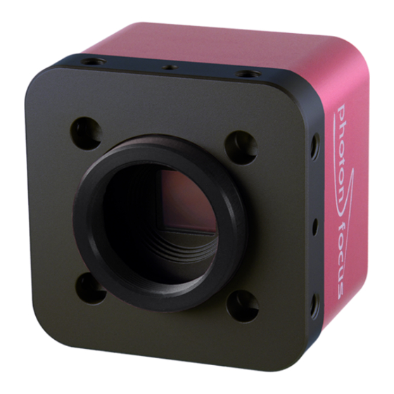
® How to get started (CameraLink ® The following items are required to operate your Photonfocus CameraLink camera: • ® • Suitable CameraLink frame grabber card to be installed in the PC. All Photonfocus ® ® CameraLink cameras are fully compatible with the CameraLink standard 1.1 and later. - Page 12 ® 2 How to get started (CameraLink Figure 2.1: Camera with protective cap and lens. To choose a lens, see the Lens Finder in the ’Support’ area at www.photonfocus.com. ® Connect the camera to the frame grabber with a suitable CameraLink cable (see Fig.
- Page 13 Check the correct supply voltage and polarity! Do not exceed the maximum operating voltage of +12V DC ( 10%). Connect the power supply to the camera (see Fig. 2.2). The status LED on the rear of the camera will light red for a short moment, and then flash green.
- Page 14 ® 2 How to get started (CameraLink Figure 2.4: PFRemote start window MAN064 02/2020 V1.1 14 of 109...
-
Page 15: Product Specification
Product Specification 3.1 Introduction The MV1-D1024E-CL CMOS camera series from Photonfocus is aimed at demanding applications in industrial image processing. It provides an exceptionally high dynamic range of up to 120 dB at a resolution of 1024 x 1024 pixels. The cameras are built around a monochrome CMOS image sensor, developed by Photonfocus. -
Page 16: Feature Overview
3 Product Specification 3.2 Feature Overview Characteristics MV1-D1024E-CL Series ® Interface CameraLink base configuration Camera Control PFRemote (Windows GUI) or programming library Configuration Interface CLSERIAL (9’600 baud up to 1.5Mbaud, user selectable) Trigger Modes Interface Trigger / External opto isolated trigger input Image pre-processing Shading Correction (Offset and Gain) 2 look-up tables (12-to-8 bit) on user-defined image region (Region-LUT) -
Page 17: Available Camera Models
3.3 Available Camera Models 3.3 Available Camera Models Please check the availability of a specific camera model on our website www.photonfocus.com. Name Resolution Color MV1-D1024E-160-CL-12 1024 x 1024 150 fps Table 3.2: Available Photonfocus MV1-D1024E-CL camera models (Footnotes: frame rate at at full reso- lution) 3.4 Difference to legacy MV-D1024E series The MV1-D1024E-160-CL-12 is a direct replacement of the MV-D1024E-160-12 camera. -
Page 18: Technical Specification
3 Product Specification 3.5 Technical Specification MV1-D1024E-160-CL Technology CMOS active pixel Scanning system progressive scan Optical format / diagonal 1” / 15.42 mm Resolution 1024 x 1024 pixels Pixel size 10.6 m x 10.6 m Active optical area 10.9 mm x 10.9 mm Random noise <... - Page 19 3.5 Technical Specification MV1-D1024E-160-CL Operating temperature 0°C ... 50°C Storage temperature / moisture -25°C ... 60°C / 20 ... 95 % Camera power supply +12 V DC ( 10%) Trigger signal input range +5 .. +15 V DC Max. power consumption 4.0 W Lens mount C-Mount, CS-Mount (optional)
-
Page 20: Frame Grabber Relevant Configuration
3 Product Specification 3.6 Frame Grabber relevant Configuration The parameters and settings, which are essential to configure the frame grabber are shown in the following table. MV1-D10124E-160-CL Pixel Clock per Tap 80 MHz Number of Taps Greyscale resolution 12 bit / 10 bit / 8 bit Line pause 8 clock cycles EXSYNC... -
Page 21: Functionality
Functionality This chapter serves as an overview of the camera configuration modes and explains camera features. The goal is to describe what can be done with the camera. The setup of the cameras is explained in later chapters. 4.1 Image Acquisition 4.1.1 Readout Modes The MV1-D1024E CameraLink series provides two different readout modes: Sequential readout Frame time is the sum of exposure time and readout time. - Page 22 4 Functionality Sequential readout mode For the calculation of the frame rate only a single formula applies: frame rate equals approximately the inverse of the sum of exposure time and readout time. Simultaneous readout mode (exposure time < readout time) The frame rate is given by the readout time.
-
Page 23: Constant Frame Rate (Cfr)
4.2 Pixel Response A x p o s u r e n i d l e e x p o s u r e n + 1 i d l e r e a d o u t n - 1 r e a d o u t n r e a d o u t n + 1 f r a m e t i m e... -
Page 24: Linlog
4 Functionality Black Level Adjustment The black level is the average image value at no light intensity. It can be adjusted by the software by changing the black level offset. Thus, the overall image gets brighter or darker. Use a histogram to control the settings of the black level. ®... - Page 25 4.2 Pixel Response changes directly to a logarithmic curve leading to a poor grey resolution in the logarithmic region (see Fig. 4.9). L i n L o g e x p V a l u e 1 = V a l u e 2 T i m e 1 = T i m e 2 = m a x .
- Page 26 4 Functionality LinLog2 ® To get more grey resolution in the LinLog mode, the LinLog2 procedure was developed. In LinLog2 mode a switching between two different logarithmic compressions occurs during the exposure time (see Fig. 4.10). The exposure starts with strong compression with a high ®...
- Page 27 4.2 Pixel Response ® Typical LinLog2 Response Curve − Varying Parameter Time1 Time2=1000, Value1=19, Value2=18 T1 = 880 T1 = 900 T1 = 920 T1 = 940 T1 = 960 T1 = 980 T1 = 1000 Illumination Intensity Figure 4.12: Response curve for different LinLog settings in LinLog2 mode LinLog3 To enable more flexibility the LinLog3 mode with 4 parameters was introduced.
-
Page 28: Skimming
4 Functionality ® Typical LinLog2 Response Curve − Varying Parameter Time2 Time1=850, Value1=19, Value2=18 T2 = 950 T2 = 960 T2 = 970 T2 = 980 T2 = 990 Illumination Intensity Figure 4.14: Response curve for different LinLog settings in LinLog3 mode 4.2.3 Skimming Skimming is a Photonfocus proprietary technology to enhance detail in dark areas of an image. -
Page 29: Reduction Of Image Size
4.3 Reduction of Image Size 4.3 Reduction of Image Size With Photonfocus cameras there are several possibilities to focus on the interesting parts of an image, thus reducing the data rate and increasing the frame rate. The most commonly used feature is Region of Interest (ROI). - Page 30 4 Functionality Exposure time MV1-D1024E-160-CL 10 s 149 / 148 fps 100 s 147 / 146 fps 500 s 139 / 139 fps 1 ms 130 / 140 fps 2 ms 115 / 140 fps 5 ms 85 / 140 fps 10 ms 60 / 99 fps 12 ms...
-
Page 31: Multiple Regions Of Interest
4.3 Reduction of Image Size 4.3.2 Multiple Regions of Interest The Photonfocus MV1-D1024E-160-CL camera can handle up to 512 different regions of interest. This feature can be used to reduce the amount image data and increase the frame rate. An application example for using multiple regions of interest (MROI) is a laser triangulation system with several laser lines. - Page 32 4 Functionality Fig. 4.18 shows another MROI drawing illustrating the effect of MROI on the image content. Figure 4.18: Multiple Regions of Interest with 5 ROIs MAN064 02/2020 V1.1 32 of 109...
-
Page 33: Decimation
4.3 Reduction of Image Size 4.3.3 Decimation Decimation reduces the number of pixels in y-direction. Decimation in y-direction transfers every n row only and directly results in reduced read-out time and higher frame rate respectively. Decimation can also be used together with ROI or MROI. In this case every ROI should have a height that is a multiple of the decimation setting. - Page 34 4 Functionality 0 , 0 ) R O I m a x m a x Figure 4.20: Decimation and ROI ( 0 , 0 ) R O I M R O I 0 M R O I 1 M R O I 2 m a x m a x Figure 4.21: Decimation and MROI...
- Page 35 4.3 Reduction of Image Size The image in Fig. 4.22 on the right-hand side shows the result of decimation 3 of the image on the left-hand side. Figure 4.22: Image example of decimation 3 An example of a high-speed measurement of the elongation of an injection needle is given in Fig.
-
Page 36: Trigger And Strobe
4 Functionality 4.4 Trigger and Strobe 4.4.1 Introduction The start of the exposure of the camera’s image sensor is controlled by the trigger. The trigger can either be generated internally by the camera (free running trigger mode) or by an external device (external trigger mode). - Page 37 4.4 Trigger and Strobe M a c h i n e V i s i o n S y s t e m + a m e r a C a m e r a L i n k F r a m e G r a b b e r P o w e r E X S Y N C ( C C 1 ) / S o f t t r i g g e r...
-
Page 38: Exposure Time Control
4 Functionality 4.4.3 Exposure Time Control Depending on the trigger mode, the exposure time can be determined either by the camera or by the trigger signal itself: Camera-controlled Exposure time In this trigger mode the exposure time is defined by the camera. - Page 39 4.4 Trigger and Strobe results then from the synchronous design of the FPGA state machines and from to trigger offset requirement to start an exposure at a fixed point from the start of the read out of a row. The exposure time t is controlled with an internal exposure time controller.
-
Page 40: Trigger Delay
4 Functionality The falling edge of the trigger pulse is delayed by the time t which results from the d iso input signal isolator. This signal is clocked into the FPGA which leads to a jitter of t . The pulse is jitter then delayed by t by the user defined value which can be configured via camera... - Page 41 4.4 Trigger and Strobe A x t e r n a l t r i g g e r p u l s e i n p u t t r i g g e r a f t e r i s o l a t o r d - i s o - i n p u t t r i g g e r p u l s e i n t e r n a l c a m e r a c o n t r o l j i t t e r...
-
Page 42: Trigger Timing Values
4 Functionality 4.4.6 Trigger timing values Table 4.4 shows the values of the trigger timing parameters. MV1-D1024E-160-CL MV1-D1024E-160-CL Timing Parameter Minimum Maximum 45 ns 60 ns d iso input 25 ns jitter 0.41 s trigger delay 0.41 s burst trigger delay depends on camera settings 0.41 s burst period time... -
Page 43: Software Trigger
4.4 Trigger and Strobe 4.4.7 Software Trigger The software trigger enables to emulate an external trigger pulse by the camera software through the serial data interface. It works with both burst mode enabled and disabled. As soon as it is performed via the camera software, it will start the image acquisition(s), depending on the usage of the burst mode and the burst configuration. -
Page 44: Data Path Overview
4 Functionality 4.5 Data Path Overview The data path is the path of the image from the output of the image sensor to the output of the camera. The sequence of blocks is shown in figure Fig. 4.30. 1 m a g e S e n s o r F P N C o r r e c t i o n D i g i t a l O f f s e t... -
Page 45: Image Correction
4.6 Image Correction 4.6 Image Correction 4.6.1 Overview The camera possesses image pre-processing features, that compensate for non-uniformities caused by the sensor, the lens or the illumination. This method of improving the image quality is generally known as ’Shading Correction’ or ’Flat Field Correction’ and consists of a combination of offset correction, gain correction and pixel interpolation. - Page 46 4 Functionality " a v e r a g e o f b l a c k r e f e r e n c e p i c t u r e > l a c k r e f e r e n c e o f f s e t c o r r e c t i o n i m a g e m a t r i x...
-
Page 47: Gain Correction
4.6 Image Correction Hot pixel correction Every pixel that exceeds a certain threshold in the black reference image is marked as a hot pixel. If the hot pixel correction is switched on, the camera replaces the value of a hot pixel by an average of its neighbour pixels (see Fig. -
Page 48: Corrected Image
4 Functionality 0 . 8 0 . 9 a v e r a g e o f g r a y 1 . 2 0 . 8 1 . 3 1 . 2 r e f e r e n c e 0 . -
Page 49: Correction Ranges
4.6 Image Correction Histogram of the uncorrected grey reference image grey reference image ok grey reference image too bright 2400 2600 2800 3000 3200 3400 3600 3800 4000 4200 Grey level, 12 Bit [DN] Figure 4.35: Proper grey reference image for gain correction 0 . -
Page 50: Gain And Offset
4 Functionality 4.7 Gain and Offset There are two different gain settings on the camera: Gain (Digital Fine Gain) Digital fine gain accepts fractional values from 0.01 up to 15.99. It is implemented as a multiplication operation. Digital Gain Digital Gain is a coarse gain with the settings x1, x2, x4 and x8. It is implemented as a binary shift of the image data where ’0’... - Page 51 4.8 Grey Level Transformation (LUT) y = f ( x ) m a x m a x Figure 4.37: Commonly used LUT transfer curves Grey level transformation − Gain: y = (255/1023) ⋅ a ⋅ x a = 1.0 a = 2.0 a = 3.0 a = 4.0 1000...
-
Page 52: Gamma
4 Functionality 4.8.2 Gamma The ’Gamma’ mode performs an exponential amplification, configurable in the range from 0.4 to 4.0. Gamma > 1.0 results in an attenuation of the image (see Fig. 4.39), gamma < 1.0 results in an amplification (see Fig. 4.40). Gamma correction is often used for tone mapping and better display of results on monitor screens. -
Page 53: User-Defined Look-Up Table
4.8 Grey Level Transformation (LUT) 4.8.3 User-defined Look-up Table In the ’User’ mode, the mapping of input to output grey levels can be configured arbitrarily by the user. There is an example file in the PFRemote folder. LUT files can easily be generated with a standard spreadsheet tool. - Page 54 4 Functionality ( 0 , 0 ) N N N N O O L U T 0 O L U T 1 O m a x m a x Figure 4.42: Overlapping Region-LUT example ( 0 , 0 )
- Page 55 4.8 Grey Level Transformation (LUT) Fig. 4.44 shows the application of the Region-LUT to a camera image. The original image without image processing is shown on the left-hand side. The result of the application of the Region-LUT is shown on the right-hand side. One Region-LUT was applied on a small region on the lower part of the image where the brightness has been increased.
-
Page 56: Crosshairs
4 Functionality 4.9 Crosshairs 4.9.1 Functionality The crosshairs inserts a vertical and horizontal line into the image. The width of these lines is one pixel. The grey level is defined by a 12 bit value (0 means black, 4095 means white). This allows to set any grey level to get the maximum contrast depending on the acquired image. - Page 57 4.9 Crosshairs ( 0 , 0 ) 0 , 0 ) , G r e y L e v e l ) a b s o l u t a b s o l u t R O I R O I , G r e y L e v e l ) a b s o l u t...
-
Page 58: Image Information And Status Line
4 Functionality 4.10 Image Information and Status Line There are camera properties available that give information about the acquired images, such as an image counter, average image value and the number of missed trigger signals. These properties can be queried by software. Alternatively, a status line within the image data can be switched on that contains all the available image information. - Page 59 4.10 Image Information and Status Line Start pixel index Parameter width [bit] Parameter Description Preamble: 0x55AA00FF Image Counter (see Section 4.10.1) Real Time Counter (see Section 4.10.1) Missed Trigger Counter (see Section 4.10.1) Image Average Value("raw" data without taking in account gain settings) (see Section 4.10.1) Integration Time in units of clock cycles (see Table 3.3) Burst Trigger Number...
-
Page 60: Camera Type Codes
4 Functionality 4.10.3 Camera Type Codes Camera Model Camera Type Code MV1-D1024E-160-CL-12 Table 4.8: Type codes of Photonfocus MV1-D1024E camera series 4.11 Test Images Test images are generated in the camera FPGA, independent of the image sensor. They can be used to check the transmission path from the camera to the frame grabber. -
Page 61: Lfsr
4.11 Test Images 12 bit: The 10 LSB are the same as in the 10 bit mode. Bits 8 and 9 of the row number (starting at 0) are mapped to the MSB 10 and 11. The two MSB of rows 0 to 255 have the value 0, the two MSB of rows 256 to 511 have the value 1, and so on. - Page 62 4 Functionality ® A possible origin of failure message can be caused by the CameraLink cable which exceeds the maximum length. The maximal cable length depends on the frequency of the pixel clock. At a pixel clock of 80 MHz, a length of 8 m can be ®...
- Page 63 4.11 Test Images ® Some thinner CameraLink cables have a predefined direction. In these cables not all twisted pairs are separately shielded to meet the RS644 standard. These pairs are used for the transmission of the RX/TX and for the CC1 to CC4 low frequency control signals.
-
Page 64: Configuration Interface (Cameralink )
4 Functionality ® 4.12 Configuration Interface (CameraLink ® A CameraLink camera can be controlled by the user via a RS232 compatible asynchronous ® serial interface. This interface is contained within the CameraLink interface as shown in Fig. 4.52 and is physically not directly accessible. Instead, the serial communication is usually routed through the frame grabber. -
Page 65: Precautions
Precautions 5.1 IMPORTANT NOTICE! READ THE INSTRUCTIONS FOR USE BEFORE OPERATING THE CAMERA STORE THE INSTRUCTIONS FOR USE FOR FURTHER READING The installation of the camera in the vision system should be executed by trained and instructed employees. DANGER - Electric Shock Hazard Unapproved power supplies may cause electric shock. - Page 66 5 Precautions Incorrect plugs can damage the camera connectors. Use only the connectors specified by Photonfocus in this manual. Using plugs designed for a smaller or a larger number of pins can damage the connectors. The cameras deliver the data to the vision system over interfaces with high band- width.
- Page 67 5.1 IMPORTANT NOTICE! Cleaning of the housing To clean the surface of the camera housing: • Before cleaning disconnect the camera from camera power supply and I/O connectors. • Do not use aggressive solvents or thinners which can damage the surface, the serial number label and electronic parts.
- Page 68 5 Precautions MAN064 02/2020 V1.1 68 of 109...
-
Page 69: Hardware Interface 6.1 Connectors
Hardware Interface 6.1 Connectors ® 6.1.1 CameraLink Connector ® The CameraLink cameras are interfaced to external components via ® ® • a CameraLink connector, which is defined by the CameraLink standard as a 26 pin, 0.5" Mini Delta-Ribbon (MDR) connector to transmit configuration, image data and trigger. •... -
Page 70: Trigger And Strobe Signals
6 Hardware Interface 6.1.3 Trigger and Strobe Signals The power connector contains an external trigger input and a strobe output. The trigger input is equipped with a constant current diode which limits the current of the optocoupler over a wide range of voltages. Trigger signals can thus directly get connected with the input pin and there is no need for a current limiting resistor, that depends with its value on the input voltage. -
Page 71: Status Indicator (Cameralink Cameras)
6.1 Connectors STROBE_VDD Pull-up Resistor 15 V > 3.9 kOhm 10 V > 2.7 kOhm > 2.2 kOhm > 1.8 kOhm > 1.0 kOhm Table 6.1: Pull-up resistor for strobe output and different voltage levels ® 6.1.4 Status Indicator (CameraLink cameras) A dual-color LED on the back of the camera gives information about the current status of the ®... - Page 72 6 Hardware Interface ® Serial communication: A CameraLink camera can be controlled by the user via a RS232 compatible asynchronous serial interface. This interface is contained within the ® CameraLink interface and is physically not directly accessible. Refer to Section 4.12 for more information.
-
Page 73: The Pfremote Control Tool
The PFRemote Control Tool 7.1 Overview PFRemote is a graphical configuration tool for Photonfocus cameras. The latest release can be downloaded from the support area of www.photonfocus.com. All Photonfocus cameras can be either configured by PFRemote, or they can be programmed with custom software using the PFLib SDK ([PFLIB]). -
Page 74: Installation Notes
7 The PFRemote Control Tool 7.4 Installation Notes Before installing the required software with the PFInstaller, make sure that your frame grabber software is installed correctly. Several DLLs are necessary in order to be able to communicate with the cameras: •... -
Page 75: Ports, Device Initialization
7.5 Graphical User Interface (GUI) File Menu Clear Log: Clears the log file buffer Quit: Exit the program Help Menu About: Copyright notice and version information Help F1: Invoke the online help (PFRemote documentation) 7.5.2 Ports, Device Initialization After starting PFRemote, the main window as shown in Fig. 7.2 will appear. In the PortBrowser in the upper left corner you will see a list of supported ports. -
Page 76: Main Buttons
7 The PFRemote Control Tool 7.5.3 Main Buttons The buttons on the right side of the configuration dialog store and reset the camera configuration. Figure 7.3: Main buttons Reset: Reset the camera and load the default configuration. Store as defaults: Store the current configuration in the camera flash memory as the default configuration. -
Page 77: Graphical User Interface (Gui)
Graphical User Interface (GUI) 8.1 MV1-D1024E-160 This section describes the parameters of the following MV1-D1024E-160-CL-12 camera. The following sections are grouped according to the tabs in the configuration dialog. Figure 8.1: Frame rate and average value indication Frame Rate [fps]: Shows the actual frame rate of the camera in frames per second. Update: To update the value of the frame rate, click on this button. -
Page 78: Exposure
8 Graphical User Interface (GUI) 8.1.1 Exposure This tab contains exposure settings. Figure 8.2: Exposure panel Exposure Exposure time [ms]: Configure the exposure time in milliseconds. Constant Frame Rate: When the Constant Frame Rate (CFR) is switched on, the frame rate (number of frames per second) can be varied from almost 0 up to the maximum frame rate. - Page 79 8.1 MV1-D1024E-160 Simultaneous readout (Interleave) The simultaneous readout mode allows higher frame rate. Simultaneous readout (Interleave): Enable the simultaneous readout mode. Combination of property Trigger.Interleave and property LinLog.Mode is not available! Combination of property Trigger.Interleave and property Trigger.LevelControlled is not available! Combination of property Trig- ger.Interleave and property Trigger.EnBurstTrigger is not available! MAN064 02/2020 V1.1...
-
Page 80: Window
8 Graphical User Interface (GUI) 8.1.2 Window This tab contains the settings for the region of interest. Figure 8.3: Window panel Region of Interest The region of interest (ROI) is defined as a rectangle (X, Y), (W, H) where X: X - coordinate, starting from 0 in the upper left corner. Y: Y - coordinate, starting from 0 in the upper left corner. - Page 81 8.1 MV1-D1024E-160 Decimation Decimation reduces the number of pixels in y-direction. Decimation can also be used together with a ROI or MROI. Decimation in y-direction transfers every n-th row only and directly results in reduced read-out time and higher frame rate respectively. Decimation Y: Decimation value for y-direction.
-
Page 82: Trigger
8 Graphical User Interface (GUI) 8.1.3 Trigger This tab contains trigger and strobe settings. Figure 8.4: Trigger panel Trigger Trigger Source: Free running: The camera continuously delivers images with a certain configurable frame rate. Interface Trigger: The Trigger signal is applied to the camera by the CameraLink frame grabber. I/O Trigger: The trigger signal is applied directly to the camera on the power supply connector. - Page 83 8.1 MV1-D1024E-160 This property disables LinLog and Burst trigger. Exposure time defined by "Trigger Pulse Width" is also known as Level controlled trigger. Further trigger settings: Trigger Delay [ms]: Programmable delay in milliseconds between the incoming trigger edge and the start of the exposure. Trigger signal active low: Define the trigger signal to be active high (default) or active low.
-
Page 84: Data Output
8 Graphical User Interface (GUI) 8.1.4 Data Output This tab contains image data settings. Figure 8.5: Data output panel Output Mode Output Mode: Normal: Normal mode. LFSR: Test image. Linear feedback shift register (pseudo-random image). The pattern depends on the grey level resolution. Ramp: Test image. - Page 85 8.1 MV1-D1024E-160 Digital Gain: 1x: No digital gain, normal mode. 2x: Digital gain 2. 4x: Digital gain 4. 8x: Digital gain 8. Digital Offset: Substracts an offset from the data. Only available in gain mode. Fine Gain: The fine gain can be used to adjust the brightness of the whole image in small steps. MAN064 02/2020 V1.1 85 of 109...
-
Page 86: Lut (Look-Up-Table)
8 Graphical User Interface (GUI) 8.1.5 LUT (Look-Up-Table) This tab contains LUT settings. Figure 8.6: LUT panel Grey level transformation is remapping of the grey level values of an input image to new values which transform the image in some way. The look-up-table (LUT) is used to convert the greyscale value of each pixel in an image into another grey value. - Page 87 8.1 MV1-D1024E-160 value: Enter a value. The LUT will be calculated and downloaded to the camera. Region LUT Both LUT can be configured with ROI vlaues. The LUT is only working inside the the ROI values. Overlapping is possible. LUT0 has higher priority. Enable Region LUT: Enable the region LUT functionality.
-
Page 88: Linlog
8 Graphical User Interface (GUI) 8.1.6 LinLog This tab contains LinLog and Skimming settings. Figure 8.7: Linlog panel LinLog The LinLog technology from Photonfocus allows a logarithmic compression of high light intensities. In contrast to the classical non-integrating logarithmic pixel, the LinLog pixel is an integrating pixel with global shutter and the possibility to control the transition between linear and logarithmic mode (See also the corresponding section in the camera manual.). - Page 89 8.1 MV1-D1024E-160 Skimming Skimming is a Photonfocus proprietary technology to enhance detail in dark areas of an image. Skimming: Skimming value. If 0, Skimming is disabled. See also the corresponding section in the camera manual. MAN064 02/2020 V1.1 89 of 109...
-
Page 90: Correction
8 Graphical User Interface (GUI) 8.1.7 Correction This tab contains correction settings. Figure 8.8: Correction panel Correction Mode This camera has image pre-processing features, that compensate for non-uniformities caused by the sensor, the lens or the illumination. Off: No correction. Offset: Activate offset correction Offset + Hotpixel: Activate offset and hot pixel correction. - Page 91 8.1 MV1-D1024E-160 Calibration Offset (FPN), Hotpixel Correction: The offset correction is based on a black reference image, which is taken at no illumination (e.g. lens aperture completely closed). The black reference image contains the fixed-pattern noise of the sensor, which can be subtracted from the live images in order to minimize the static noise.
-
Page 92: Info
8 Graphical User Interface (GUI) 8.1.8 Info This panel shows camera specific information such as type code, serial number and firmware revision of the FPGA and microcontroller and the description of the camera interface. Figure 8.9: Info panel Camera Info Camera name: Name of the connected camera. - Page 93 8.1 MV1-D1024E-160 Baudrate: The actual baud rate between camera and frame grabber. For any support requests, please enclose the information provided on this panel. Counters The camera has the following counters. Image: The image counter is a 24 bit real-time counter and is incremented by 1 for every new image.
- Page 94 8 Graphical User Interface (GUI) MAN064 02/2020 V1.1 94 of 109...
-
Page 95: Mechanical And Optical Considerations
Mechanical and Optical Considerations 9.1 Mechanical Interface for CameraLink Camera Models Fig. 9.1 shows the mechanical drawings of the CameraLink camera models. Table 9.1 summarizes model-specific parameters. During storage and transport, the camera should be protected against vibration, shock, moisture and dust. The original packaging protects the camera adequately from vibration and shock during storage and transport. -
Page 96: Adjusting The Back Focus
9 Mechanical and Optical Considerations 9.2 Adjusting the Back Focus The back focus of your Photonfocus camera is correctly adjusted in the production of the camera. This section describes the procedure to adjust the back focus if you require that because e.g. you are using a special lens. -
Page 97: Optical Interface
9.3 Optical Interface 9.3 Optical Interface 9.3.1 Cleaning the Sensor The sensor is part of the optical path and should be handled like other optical components: with extreme care. Dust can obscure pixels, producing dark patches in the images captured. Dust is most visible when the illumination is collimated. - Page 98 9 Mechanical and Optical Considerations Product Supplier Remark EAD400D Airduster Electrolube, UK www.electrolube.com Anticon Gold 9"x 9" Wiper Milliken, USA ESD safe and suitable for class 100 environments. www.milliken.com TX4025 Wiper Texwipe www.texwipe.com Transplex Swab Texwipe Small Q-Tips SWABS Q-tips Hans J.
-
Page 99: Standards Compliance
Standards Compliance 10.1 Directives and General Standards The products described in this manual in the form as delivered are in conformity with the provisions of the following European Directives: • 2014/30/EU Electromagnetic compatibility (EMC) • 2014/35/EU Low Voltage (LVD) • 2011/65/EU Restriction of hazardous substances (RoHS) Conformity to the Directives is assured through the application of the following standards: Emission:... -
Page 100: For Customers In Canada
10 Standards Compliance likely to cause harmful interference in which case the user will be required to correct the interference at his own expense. You are cautioned that any changes or modifications not expressly approved in this manual could void your authority to operate this equipment. The shielded interface cable recommended in this manual must be used with this equipment in order to comply with the limits for a computing device pursuant to Subpart B of Part 15 of FCC Rules. -
Page 101: Warranty
Warranty The manufacturer alone reserves the right to recognize warranty claims. 11.1 Warranty Terms The manufacturer warrants to distributor and end customer that for a period of two years from the date of the shipment from manufacturer or distributor to end customer (the "Warranty Period") that: •... - Page 102 11 Warranty Avoid cleaning the sensor with improper methods. Follow the instructions in the corresponding chapter of this manual. Transport and store the camera in its original packaging only and protect the sensor and the lens mount with a camera body cap. 10.
-
Page 103: References
References All referenced documents can be downloaded from our website at www.photonfocus.com. ® CL CameraLink Specification, January 2004 SW002 PFLib Documentation, Photonfocus, August 2005 AN001 Application Note "LinLog", Photonfocus, December 2002 AN007 Application Note "Camera Acquisition Modes", Photonfocus, March 2004 AN008 Application Note "Photometry versus Radiometry", Photonfocus, December 2004 AN010 Application Note "Camera Clock Concepts", Photonfocus, July 2004 ®... - Page 104 12 References MAN064 02/2020 V1.1 104 of 109...
-
Page 105: A Pinouts
Pinouts A.1 Power Supply Connector The power supply plugs are available from Binder connectors at www.binder-connector.de. Fig. A.2 shows the power supply plug from the solder side. The pin assignment of the power supply plug is given in Table A.2. It is extremely important that you apply the appropriate voltages to your camera. - Page 106 A Pinouts " Figure A.2: Power supply plug, 7-pole (rear view of plug, solder side) I/O Type Name Description +12 V DC ( 10%) Ground RESERVED Do not connect STROBE-VDD +5 .. +15 V DC STROBE Strobe control (opto-isolated) TRIGGER External trigger (opto-isolated), +5 ..
-
Page 107: Cameralink Connector
® A.2 CameraLink Connector Name Description SHIELD Shield ® N_XD0 Negative LVDS Output, CameraLink Data D0 ® N_XD1 Negative LVDS Output, CameraLink Data D1 ® N_XD2 Negative LVDS Output, CameraLink Data D2 ® N_XCLK Negative LVDS Output, CameraLink Clock ® N_XD3 Negative LVDS Output, CameraLink Data D3... - Page 108 A Pinouts MAN064 02/2020 V1.1 108 of 109...
-
Page 109: B Revision History
Revision History Revision Date Changes September 2014 First version February 2020 Chapter CE Compliance updated; chapter Precautions added; new camera image inserted MAN064 02/2020 V1.1 109 of 109...
Need help?
Do you have a question about the MV1-D1024E Series and is the answer not in the manual?
Questions and answers