Gree Neo GWH09MA-A3DNA3A Installation, Service & Troubleshooting
Ductless system
Hide thumbs
Also See for Neo GWH09MA-A3DNA3A:
- Installation manual (24 pages) ,
- Owner's manual (24 pages) ,
- Quick start manual (2 pages)
Table of Contents
Advertisement
Neo
DUCTLESS SYSTEM
Installation, Service & Troubleshooting
Models:
GWH09MA-A3DNA3A
GWH12MB-A3DNA3A
GWH09MB-D3DNA3D
GWH12MB-D3DNA3D
GWH18MC-D3DNA3D
GWH24MD-D3DNA3D
GWH30LB-D3DNA3E
GWH36LB-D3DNA3E
Advertisement
Table of Contents
Troubleshooting

Related Manuals for Gree Neo GWH09MA-A3DNA3A


Summary of Contents for Gree Neo GWH09MA-A3DNA3A
- Page 1 DUCTLESS SYSTEM Installation, Service & Troubleshooting Models: GWH09MA-A3DNA3A GWH12MB-A3DNA3A GWH09MB-D3DNA3D GWH12MB-D3DNA3D GWH18MC-D3DNA3D GWH24MD-D3DNA3D GWH30LB-D3DNA3E GWH36LB-D3DNA3E...
-
Page 2: Table Of Contents
Table of Contents Safety Precautions & Warnings......................... Model Number Identification..........................Physical & Electrical Data..........................6 - 9 System Overview..............................Refrigeration Cycles and Components......................11 - 15 Indoor & Outdoor Components........................16 - 18 Basic & Protection Functions..........................19 -52 Remote Control Operation..........................53 - 57 Refrigerant Lines, Connection, Evacuating and Charging................ - Page 3 Table of Contents Disassembly of 24,000 btuh 240 volt Outdoor Systems................. 184 - 188 Disassembly of 240 volt Indoor Systems......................189 - 197 Disassembly of 30,000 & 36,000 240 volt Indoor Systems................198 - 204 Appendix 1 - 3 Temperature Sensor Resistance Tables.................. 205 - 210...
-
Page 4: Safety Precautions & Warnings
Safety Precautions & Warnings Warning Caution Installing, starting up, and servicing air conditioner can be • Never install the unit in a place where a combustible hazardous due to system pressure, electrical components, gas might leak, or it may lead to fire or explosion. and equipment location, etc. -
Page 5: Model Number Identification
Model Number Identification Model Number Identification Product Catalog Number-Nomenclature G W H 09 MA A 3 D N A 2 B / I GREE I - Indoor Unit R410a O - Outdoor Unit A - 115 vac D - 208/230 vac... -
Page 6: Physical & Electrical Data
Physical & Electrical Data, cont. Model GWH09MA-A3DNA3A GWH12MB-A3DNA3A System Type Heat Pump Power Supply 115V / 60Hz 115V / 60Hz Rated Current Cooling Amps Standard 7.0 / High 16.8 Standard 11.0 / High 17.0 Rated Current Heating Amps Standard 7.5 / High 17.0 Standard 12.5 / High 18.2 System Performance Cooling Cap (Min/Max) - Page 7 Physical & Electrical Data, cont. Model GWH09MB-D3DNA3D GWH12MB-D3DNA3D System Type Heat Pump Power Supply 208 / 230v / 60Hz 208 / 230V / 60Hz Rated Current Cooling Amps Rated Current Heating Amps System Performance Cooling Cap (Min/Max) Btu/h 9,000 (3,500-9,600)) 12,000 (3,100-13,500) Heating Cap (Min/Max) Btu/h...
- Page 8 Physical & Electrical Data, cont. Model GWH18MC-D3DNA3D GWH24MD-D3DNA3D System Type Heat Pump Power Supply 208-230v / 60Hz 208-230V / 60Hz Rated Current Cooling Amps Rated Current Heating Amps System Performance Cooling Cap (Min/Max) Btu/h 18,000 (5,970-22,350) 21,400 (9,600-25,000) Heating Cap (Min/Max) Btu/h 19,800 (4,100-22,000) 23,000 (4,300-26,000)
- Page 9 Physical & Electrical Data, cont. Model GWH30LB-D3DNA3E GWH36LB-D3DNA3E System Type Heat Pump Power Supply 208-230v / 60Hz 208-230V / 60Hz Rated Current Cooling Amps 12.1 15.9 Rated Current Heating Amps 12.5 15.5 System Performance Cooling Cap (Min/Max) Btu/h 28,000 (9,500-30,000)) 33,600 (7,400-36,000) Heating Cap (Min/Max) Btu/h...
-
Page 10: System Overview
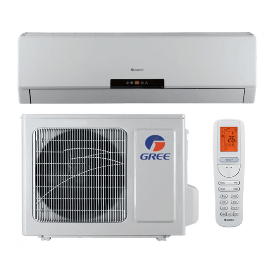
Product Introduction System Overview The Neo Ductless split heat pumps are single zone units available in size from 9000 btuh to 36,000 btuh providing heating and cooling. All comfort settings are Indoor Display controlled by a remote control. The Neo unit has many features to enhance comfort and efficiency. - Page 11 Product Introduction Refrigeration Components Outdoor Unit Indoor Unit Strainer Temperature Sensor Heat Temperature Exchanger Sensor Heat Exchanger 4-way High Pressure Switch Electronic Expansion Valve Compressor Accumulator Note: Component locations may vary depending on models.
-
Page 12: Cooling Mode
Cooling Mode Product Introduction Cooling Mode Outdoor Unit Strainer Indoor Unit Temperature Heat Sensor Strainer Exchanger Electronic expansion valve Heat Exchanger 4-way 4-way valve valve Note: Discharge Silencer Please refer to actual model for exact piping arrangement, refrigeration components may vary. - Page 13 Product Introduction Cooling Mode A. Hot gas is discharged from the compressor. The temperature of the gas is monitored by the Discharge Temperature sensor and sent to the outdoor control panel. B. The hot gas is directed through the 4-way valve, then enters the outdoor coil. The hot gas will be slightly subcooled, however there are no pressure ports to take measurements.
- Page 14 Product Introduction Heating Mode Outdoor Unit Filter Temperature Heat Indoor Unit Sensor Exchanger Electronic expansion valve Heat Exchanger 4-way 4-way valve valve Discharge Silencer Note: Please refer to actual model for exact piping Discharge arrangement, refrigeration components may Temperature vary. Sensor Accumulator not on all sizes...
- Page 15 Product Introduction Heating Mode A. Hot gas is discharged from the compressor. The temperature of the gas in monitored by the Discharge Temperature sensor and sent to the outdoor control panel. B. The hot gas is directed through the 4-way valve to the appropriate indoor coil making the line a hot gas line. C.
- Page 16 Product Introduction Indoor Unit Components Neo 12,000 btuh model Other Neo models may very slightly. Indoor Circuit Board Fan Motor Indoor Tube Thermistor Ambient Swing Motor Temperature Sensor...
- Page 17 Product Introduction Outdoor Unit Components Neo 12,000 btuh Outdoor Unit Other Neo models may very slightly. Outdoor Fan AP1 Board Reactor 4-Way Valve Exhaust Temp Sensor High Pressure Switch Compressor Note: Component locations may vary depending on models.
- Page 18 Product Introduction Outdoor Unit Components Outdoor Air Sensor Electronic Expansion Valve Outdoor tube Sensor...
- Page 19 Product Introduction Basic Functions - 9K & 12K 115 volt 6.2 Brief Description of Modes and Functions 1.Temperature Parameters ◆ Indoor preset temperature (Tpreset) ◆ Indoor ambient temperature (Tamb.) 2.Basic Functions Once the unit energized,the compressor shall never be restarted except 3mins interval at least.For the first energization,if the unit is at off status before power failure, the compressor can be restarted without 3-min delay.
- Page 20 Product Introduction Basic Functions - 9K & 12K 115 volt 5.Cold Air Prevention After the compressor starts, the indoor unit and louvers run in the mode below: 1. When Tindoor ambient<75°F: if Ttube≤104°F, the indoor fan doesn’t run and then the indoor fan runs in low fan speed after 2min.
- Page 21 Product Introduction Basic Functions - 9K & 12K 115 volt 2. Clock Timer (it’s optional for the remote controller with clock timer) Timer ON If timer ON is set during operation of the unit, the unit will continue to operate. If timer ON is set at unit OFF, upon ON time reaches the unit will start to operate according to previous setting status.
- Page 22 Product Introduction Basic Functions - 9K & 12K 115 volt (6) X-fan Function 1. X-fan function can be set in cooling or drying mode (X-fan function is unavailable in auto, heating or fan mode). When X-fan is ON, after pressing ON/OFF button to turn off the unit, indoor unit will run in low fan speed for 2min(in 2min, the horizontal louver is in the minimum angel of swinging, other loads are off).
- Page 23 Product Introduction Basic Functions - 9K & 12K 115 volt (8) Up and Down Swing Function After turning on the unit, the louver will operate in the below angel. (if the remote controller is pressed continuously within 2 seconds, the last signal will be executed, the previous signals will be invalid) After energizing, the up and down swing motor will firstly rotate the louver to position 0 anticlockwise (close in 138°) and close the air outlet.
- Page 24 Product Introduction Basic Functions - 9K & 12K 115 volt (11) I FEEL Function(reserved) When I FEEL command is received and controller has received the ambient temperature sent by remote controller, the controller will operate at the temperature sent by remote controller (For cold air prevention, the unit operates accord- ing to the ambient temperature sensed by the air conditioner).
- Page 25 Product Introduction Left Intentionally Blank...
- Page 26 Product Introduction Basic Functions - 9K & 12K 230 volt ◆ Indoor preset temperature (Tpreset) ◆ Indoor ambient temperature (Tamb.) 2. Basic Functions Once energized, in no case should the compressor be restarted within less than 3 minutes. In the situation that memory functionis available, for the first energization, if the compressor is at stop before de-energization, the compressor will be started without a3-minute lag;...
- Page 27 Product Introduction Basic Functions - 9K & 12K 230 volt 3. If Tpreset-(Tindoor ambient- Tcompensatory) ≤-3.6°F, the compressor will stop and the outdoor fan will stop with a time lag of 30s; 4. If turning off the unit when the unit is in heating mode or switching heating mode to another mode, the 4-way valve will be powered off after the compressor stops for 2min (the compressor has already started in heating mode).
- Page 28 Product Introduction Basic Functions - 9K & 12K 230 volt ◆ Total current up and frequency down protection When total current Itotal≤6A, increase frequency is allowed; when total current Itotal≥7A, increasing frequency is prohibited; when total current Itotal≥8A, the unit operates by decreasing frequency. When total current Itotal≥9A, the compressor stops operation, and indoor fan will stop operation after 30s.
- Page 29 Product Introduction Basic Functions - 9K & 12K 230 volt 5. Overload protection If temperature sensed by the overload sensor is over 239°F, the compressor will stop and the outdoor fan will stop with a time lag of 30 seconds. If temperature is below 203°F, the overload protection will be relieved. 6.
- Page 30 Product Introduction Basic Functions - 9K & 12K 230 volt (7) Buzzer Control The buzzer will send a “Di” sound when the air conditioner is powered up or received the information sent by the remote control or there is a button input, the single tube cooler doesn’t receive the remote control ON signal under the mode of heating mode.
- Page 31 Product Introduction Basic Functions - 9K & 12K 230 volt (11) Drying Function You may start or stop the drying function under the modes of cooling and dehumidify at the starting status (The modes of automatism, heating and air supply do not have drying function). When you start the drying function, after stop the machine by pressing the switch button, you should keep running the inner fans for 2 minutes under low air damper (The swing will operate as the former status within 2 minutes, and other load is stopped), then stop the entire machine;...
- Page 32 Product Introduction Basic Functions - 9K & 12K 230 volt (15) Refrigerant recovery function (applicable for moving the unit or maintaining the unit) (1) Start up refrigerant recovery function Set cooling mode with remote controller within 5min after energization, adjust temperature at 16OC and press light button on remote controller for 3 times successively to any one indoor unit within 3s and then the complete unit will enter into refrigerant recovery status.
-
Page 33: Indoor Unit
Product Introduction Basic Functions - 18K & 24K 230 volt Indoor Unit A. Basic function of system (1) Cooling mode 1.Under this mode, fan motor, swing will work under setting status, the temp. range is 61-86 2.Outdoor unit malfunction or unit stop running, indoor unit will keep original running status, malfunction displayed. - Page 34 Product Introduction Basic Functions - 18K & 24K 230 volt B. Display state of indoor indicators (1) State of indoor display board 1. When the unit is powered on, all patterns will be displayed and then only power indicator is on. When the unit is turned on with a remote controller, the operating indicator is on and operation mode which is set currently is displayed.
- Page 35 Product Introduction Basic Functions - 18K & 24K 230 volt (1) Up and down wind blow functions When the unit is powered on, the up and down wind blow motor will turn a wind deflector anti-clockwise to Position 0 to shut down the air outlet. When the unit is switched on and wind blow function is not preset, under the heating mode, up and down wind blades will turn clockwise to position D;...
- Page 36 Product Introduction Basic Functions - 18K & 24K 230 volt Timing change: When the system is in timing mode, start and stop can be set through the On/Off button on the remote controller; or timing time can be reset and the system will operate according to the latest setting. When the system is in operation and both timing start and stop are set, the system will stay at currently set operation state.
- Page 37 Product Introduction Basic Functions - 18K & 24K 230 volt 2. When the thermo-bulb is detected in open circuit continuously for 30 seconds: stop the machine in protection, directly display corresponding faults of the thermo-bulb. 3. Forced Running Function of the Indoor Units (1) Enter into Forced Running Control Within 5 minutes after power-up, press the Lights Off button on the remote controller continuously for three times within 3 seconds to enter into the fluorine collecting mode, and display Fo, send the fluorine-collecting mode for 25 minutes continuously, each load will be treated as cooling when starting the...
-
Page 38: Outdoor Unit
Product Introduction Basic Functions - 18K & 24K 230 volt Outdoor Unit A. Input Parameter Compensation and Calibration (1) Check the ambient temperature compensation function Indoor ambient temperature compensation function a. In cooling mode, the indoor ambient temperature participating in computing control = (Tindoor ambient temperature -Tcooling indoor ambient temperature compensation) b. - Page 39 Product Introduction Basic Functions - 18K & 24K 230 volt (4) Heating Mode 1. Conditions and processes of heating operations: (Tindoor ambient temperature is the actual detection temperature of indoor environment thermo-bulb,Theating indoor ambient temperature compensation is the indoor ambient temperature compensation during heating operations) (1) If the compressor is shut down, and [(Tindoor ambient temperature - Theating indoor ambient temperature compensation) - Tsetup] ≤...
- Page 40 Product Introduction Basic Functions - 18K & 24K 230 volt (2) Outer Fans Control Notes: Only the outer fans run for at least 80s in each air flow speed can the air flow be switched; after the outer fans run compulsively in high speed for 80s when the machine starts up, control the air flow according to the logic.
- Page 41 Product Introduction Basic Functions - 18K & 24K 230 volt (5) Overload protection function Overload protection function at the mode of Cooling and dehumidifying 1. Starting estimation: After the compressor stopped working for 180s, if Touter pipe <[TCooling overload frequency- limited temperature](the temperature of hysteresis is 35.6 °F), the machine is allowed to start, otherwise it should not be started, and should be stopped to treat according to the overload protection: Clear the trouble at the mode of power turn-off / heating, and the protection times are not counted.
- Page 42 Product Introduction Basic Functions - 18K & 24K 230 volt 1. Frequency limited If[Theating overload frequency-limited temperature]≤Tinner pipe<[Theating overload frequency reducing temperature at normal speed], you should limit the frequency raising of compressor. 2. Reducing frequency at normal speed and stopping machine: If [Theating overload frequency reducing temperature at normal speed]≤Tinner pipe<...
- Page 43 Product Introduction Basic Functions - 18K & 24K 230 volt 3. Reducing frequency at normal speed and stopping machine: If [Tfrequency reducing temperature at normal speed during discharging]≤TDischarge< [Tfrequency reducing temperature at high speed during discharging] you should adjust the compressor frequency by reducing 8Hz/90s till the lower limit;...
- Page 44 Product Introduction Basic Functions - 18K & 24K 230 volt (8)Module protection Testing the module protective signal immediately after started, once the module protective signal is measured, stop the machine with module protection immediately. If the module protection is resumed, the machine will be allowed to operate. If the module protection continuously occurs for three times, it should not be resumed automatically, and you should press the ON/OFF button to resume.
- Page 45 Product Introduction Basic Functions - 18K & 24K 230 volt (10)Compressor overloads protection If you measure the compressor overload switch action in 3s, the compressor should be stopped for overloading. The machine should be allowed to operate after overload protection was measured to resume. If the overloading protection continuously occurs for three times, it should not be resumed automatically, and you should press the ON/OFF button to resume.
- Page 46 Product Introduction Basic Functions - 18K & 24K 230 volt (14) Voltage Abnormality Protection for DC Bus To detect voltage abnormality protection for dc bus after completing the pre-charge: 1.Over-High Voltage Protection for DC Bus If it found the DC bus voltage UDC>[UDC Jiekuangchun Protection], turn off PFC and stop the compressor at once, and it shall show the DC over-high voltage failure;...
- Page 47 Product Introduction Basic Functions - 18K & 24K 230 volt (17) Failure Detection for Sensor 1. Outdoor Ambient Sensor: detect the failure of sensor at all times. 2. Outdoor Tube Sensor: You should not detect the failure of outdoor tube sensor within 10 minutes heating operation compressor except the defrosting, and you could detect it at other time.
- Page 48 Product Introduction Basic Functions - 30K & 36K 230 volt 1. Temperature Parameters • Indoor preset temperature (Tpreset) • Indoor ambient temperature (Tamb.) 2. Basic Functions Once energized, in no case should the compressor be restarted within less than 3 minutes. In the situation that memory function is available, for the first energization, if the compressor is at stop before de-energization, the compressor will be started without a 3-minute lage;...
- Page 49 Product Introduction Basic Functions - 30K & 36K 230 volt If Tpreset -3.6ºF < Tamb < Tpreset +1.8ºF, the compressor remains at its original operation state. If Tamb < Tpreset -3.6ºF, the compressor will stop, the outdoor fan will stop with a time lag of 60s, and the indoor fan will operate at low speed.
- Page 50 Product Introduction Basic Functions - 30K & 36K 230 volt 2. In the case of Tindoor amb <75F : if Ttube < 108F, the indoor fan will run at low speed, and after one minute, the indoor fan will be converted to preset speed. Within one-minute low speed operation, if Ttube >...
- Page 51 Product Introduction Basic Functions - 30K & 36K 230 volt (6) Common Protection Functions and Fault Display under COOL, HEAT, DRY and AUTO Modes A. Overload protection Ttube: measured temperature of outdoor heat exchanger under cooling mode; and measure temperature of indoor heat exchanger under heating mode.
- Page 52 Product Introduction Basic Functions - 30K & 36K 230 volt Designation of Sensors Faults The sensor is detected to be open-circuited or short-cir- Indoor Ambient Temperature cuited for successive 30 seconds The sensor is detected to be open-circuited or short-cir- Indoor Tube Temperature cuited for successive 30 seconds The sensor is detected to be open-circuited or short-cir-...
-
Page 53: Remote Control Operation
Remote Control Operation Remote Buttons Note: This remote control is used in other models and some features may or may not be available. Consult the owners manual for specific features for your model. There should be no obstructions between the remote control and the indoor unit for proper operation. - Page 54 Remote Control Operation Display Icons 15. Mode Icon 16. Lock Icon 17. Light Icon 18. Sleep Icon 19. Temp Icon 20. Up & Down Swing Icon 21. Left & Right Swing Icon 22. Set Time Display 23. Digit Display 24. Fan Speed Display Se explanations next page.
- Page 55 Product Introduction Remote Controller Functions 1)On/Off Press this button to turn unit on or off 2)Mode Press the “Mode” button to change from Auto, Cool, Dry, Fan or Heat Pump 3)Lower Temperature Setting Each time you press the “-” button the temperature setting will lower by 10 F. Hold button down for 2 seconds to rapidly decrease setting.
- Page 56 Product Introduction Remote Controller Functions 12) Turbo Button Press this button to enable the Turbo function. This will increase the fan speed to achieve room set temperature in the shortest amount of time. 13) Sleep Button Sets sleep mode function, see owners manual for specific model information 14) Light Button Press this button to turn on or off the display light.
- Page 57 Product Introduction Remote Controller Functions 23) Digital Display This area will show the set temperature. In save mode, “SE” will be displayed. 24) Fan Speed Display The fan speed will be displayed in this area, except the “Auto” mode Auto Button (Manual Override) - Located on indoor unit.
- Page 58 Refrigerant Lines Connection, Evacuating and Charging Refrigerant Lines Preparation & Connection The refrigerant lines should be kept sealed until ready to be connected. Follow the following steps to insure a quality leak proof installation: Step 1. Refrigerant Line Connection Carefully bend and cut the tubing to prepare for flaring. Use a flaring tool designed for R410a, following the recommended manufacturer’s procedure.
- Page 59 Refrigerant Charging Procedure Please refer to your units installation manual for proper charge. If your lineset exceeds the chart below for your model, additional charge may be required. The charge must we weighed in with a refrigerant charging scale. You can only add additional refrigerant to a new installation. If a low or high charge is suspected, you must reclaim the refrigerant, then weigh in the correct amount per specifications including any additional for long linesets.
- Page 60 Refrigerant Charging Procedure 2. Leak Testing Follow the procedures for leak testing with nitrogen prior to adding charge on a new installation or existing one suspected for leaks. See preceding page. 3. Attach hoses to the unit and vacuum pump 5/16”...
- Page 61 Refrigerant Charging Procedure, cont. 5. Begin adding additional refrigerant Charging should be completed with the unit off (not running) and through the liquid side with liquid refrigerant. If there are no ports on the liquid side, use the gas side port connection, charging with liquid. Record the amount of additional charge for future reference.
- Page 62 Installation Proper installation site is vital for correct and efficient operation of the unit. Avoid the following sites where: • Strong heat sources, vapors, flammable gas or volatile liquids are emitted. • High-frequency electro-magnetic waves are generated by radio equipment, welders and medical equipment. •...
- Page 63 Installation Mounting Plate Installation 1. The mounting plate should be installed horizontally and level. 2. Measure the center of the indoor unit. Please note, that depending on model, the center of the bracket may not correspond with the center of the unit. 3.
- Page 64 Installation Install Drain Hose 1. Connect the drain hose to the outlet pipe of the indoor unit using appropriate connections. 2. Insulate the condensate to prevent condensation. 3. Fasten the condensate, lineset and wring together to prevent damage and movement. Slant the drain hose downward for smooth drainage.
- Page 65 Installation Pressure and Leak Test 1. Use only dry nitrogen with a pressure regulator for pressurizing unit. Pressurize with 150 psi of dry nitro- gen. 2. Apply soap and water to check whether the joints are leaky. A leak detector can also be applied for a leakage test.
- Page 66 Installation Connect the Outdoor Wiring Note: Confirm proper voltage before connecting wires. 1. Remove the handle on the right side plate of the out- door unit. 2. Connect wiring from indoor unit to 1,2,3 & ground, being careful to match color code of indoor connections.
- Page 67 Filter Maintenance and Emergency Operation Cleaning Air Filter 1. Lift up the front panel to access the air filter. Fig A 2. The first stage filter can be cleaned with a vacuum cleaner or by washing with a mild soap and < 113º F water.
-
Page 68: Electrical Schematics
Electrical Schematics GWH09MA-A3DNA1A/O GWH12MB-A3DNA1A/O 115 vac Symbol Color Symbol Symbol Color Symbol Orange Earth Ground White COMP. Compressor Yellow CT1,2 Overload 4-Way Valve YEGN Yellow-Green Terminal Block Brown Violet Blue Black Indoor Board Circuit diagrams are subject to change without notice, please refer to the one supplied with the unit. - Page 69 Electrical Schematics GWH09MA-A3DNA1A/O GWH12MB-A3DNA1A/O 115 vac Symbol Color Symbol Symbol Color Symbol Orange Earth Ground White COMP. Compressor Yellow CT1,2 Overload 4-Way Valve YEGN Yellow-Green Terminal Block Brown Violet Blue Black Outdoor Unit Circuit diagrams are subject to change without notice, please refer to the one supplied with the unit.
- Page 70 Electrical Schematics GWH09MA-D3DNA1A/O Indoor Board GWH12MB-D3DNA1A/O 240vac Symbol Color Symbol Symbol Color Symbol Orange Earth Ground White COMP. Compressor Yellow CT1,2 Overload 4-Way Valve YEGN Yellow-Green Terminal Block Brown Violet Blue Black Circuit diagrams are subject to change without notice, please refer to the one supplied with the unit.
- Page 71 Electrical Schematics GWH09MA-D3DNA1A/O Outdoor Board GWH12MB-D3DNA1A/O 240vac Symbol Color Symbol Symbol Color Symbol Orange Earth Ground White COMP. Compressor Yellow CT1,2 Overload 4-Way Valve YEGN Yellow-Green Terminal Block Brown Violet Blue Black Circuit diagrams are subject to change without notice, please refer to the one supplied with the unit.
- Page 72 Electrical Schematics GWH18MC-D3DNA3D Indoor Board Symbol Color Symbol Symbol Color Symbol Orange Earth Ground White COMP. Compressor Yellow CT1,2 Overload 4-Way Valve YEGN Yellow-Green Terminal Block Brown Vilolet Blue Black Circuit diagrams are subject to change without notice, please refer to the one supplied with the unit.
- Page 73 Electrical Schematics Outdoor Board GWH18MC-D3DNA3D Symbol Color Symbol Symbol Color Symbol Orange Earth Ground White COMP. Compressor Yellow CT1,2 Overload 4-Way Valve YEGN Yellow-Green Terminal Block Brown Violet Blue Black Circuit diagrams are subject to change without notice, please refer to the one supplied with the unit.
- Page 74 Electrical Schematics GWH24MD-D3DNA3D Indoor Board Symbol Color Symbol Symbol Color Symbol Orange Earth Ground White COMP. Compressor Yellow CT1,2 Overload 4-Way Valve YEGN Yellow-Green Terminal Block Brown Violet Blue Black Circuit diagrams are subject to change without notice, please refer to the one supplied with the unit.
- Page 75 Electrical Schematics GWH24MD-D3DNA3D Outdoor Board Symbol Color Symbol Symbol Color Symbol Orange Earth Ground White COMP. Compressor Yellow CT1,2 Overload 4-Way Valve YEGN Yellow-Green Terminal Block Brown Violet Blue Black Circuit diagrams are subject to change without notice, please refer to the one supplied with the unit.
- Page 76 Electrical Schematics GWH30LB-D3DNA3E Indoor Board Symbol Color Symbol Symbol Color Symbol Orange Earth Ground White COMP. Compressor Yellow CT1,2 Overload 4-Way Valve YEGN Yellow-Green Terminal Block Brown Violet Blue Black Circuit diagrams are subject to change without notice, please refer to the one supplied with the unit.
- Page 77 Electrical Schematics GWH30LB-D3DNA3E Outdoor Board Symbol Color Symbol Symbol Color Symbol Orange Earth Ground White COMP. Compressor Yellow CT1,2 Overload 4-Way Valve YEGN Yellow-Green Terminal Block Brown Violet Blue Black Symbol Name Electric Heater Terminal Board Main PC Board L1/L2 Reactor Comp Compressor...
- Page 78 Electrical Schematics GWH36LB-D3DNA3E Indoor Board Symbol Color Symbol Symbol Color Symbol Orange Earth Ground White COMP. Compressor Yellow CT1,2 Overload 4-Way Valve YEGN Yellow-Green Terminal Block Brown Blue Black Circuit diagrams are subject to change without notice, please refer to the one supplied with the unit.
- Page 79 Electrical Schematics GWH36LB-D3DNA3E Outdoor Board Symbol Color Symbol Symbol Color Symbol Orange Earth Ground White COMP. Compressor Yellow CT1,2 Overload 4-Way Valve YEGN Yellow-Green Terminal Block Brown Violet Blue Black Symbol Name Electric Heater Terminal Board Main PC Board L1/L2 Reactor Comp Compressor...
- Page 80 Printed Circuit Boards AP-1 Circuit Board Outdoor Fan Wires Compressor Wires Compressor Heater Band Thermistor wires...
-
Page 81: Troubleshooting Indoor Components
Troubleshooting Indoor Components Indoor Fan Motor Troubleshooting To check the condition of the indoor fan motor voltage measurements and resistance measurements can be compared to the following charts. Care must be taken when checking voltage measurements, all wires and terminals must be isolated for safety. - Page 82 Troubleshooting Indoor Components Step Motor Troubleshooting To check the condition of the indoor step (swing) motor resistance measurements may be compared to the following chart. Resistance measurements must be taken with power off and the connector removed from the board. The following charts indicates approximate readings and may vary with different models.
-
Page 83: Troubleshooting Outdoor Components
Troubleshooting Outdoor Components EEV Troubleshooting Heating Mode Cooling Mode Input Output Output Input To check the operation of the EEV Valve in cool- To check the operation of the EEV Valve in heating ing mode, using a digital thermometer record mode, using a digital thermometer record the tem- the temperature of the input line and the output perature of the input line and the output line of the... - Page 84 Troubleshooting Outdoor Components 4-Way Valve Troubleshooting Heating Mode Cooling Mode Compressor Compressor To Accumulator Discharge Discharge To Accumulator To Condenser To Condenser Coil Suction Line Coil Suction Line Checking the 4-way valve in cooling mode requires Checking the 4-way valve in heating mode re- the measurement of 4 readings.
- Page 85 Troubleshooting Outdoor Components Temperature Sensor Check Temperature Sensor Using a glass of ice water, place the sensor into the glass with a digital thermometer. Wait a few minutes for the reading to stabilize. Compare the readings to the sensor tables in Appendix “A”, it the reading are not compara- ble, replace the sensor.
- Page 86 Troubleshooting Outdoor Components Compressor Windings Compressor Windings Red, Yellow & Blue Wires Slightly depress tab for easy removal Compressor Winding Resistance Check: Remove the compressor wires from the AP1 circuit board. The wires red to yellow, yellow to blue & red to blue should have readings from 2 - 4 ohms.
- Page 87 Troubleshooting Outdoor Components Outdoor Fan Motor Outdoor Motor Winding Resistance Check: Disconnect power to the unit, all reading are made with no power and fan motor wires disconnected from circuit board. Remove the white and orange wire from the reactor and then disconnect the plug from the circuit board. The chart below will indicate the approximate resistance values in ohms.
- Page 88 Troubleshooting Outdoor Components Reactor Reactor Resistance Check: The line reactor helps to smooth the inrush current , reduce harmonics and noise, and buffers the system, pro- tecting the electronics from transient voltage noise. The resistance between the coils will be very low, approxi- mately .3 ohms and should not have any resistance to ground.
- Page 89 Troubleshooting Outdoor Components Gas Line Temperature Sensors Motor These sensors are a negative coefficient thermistor that decrease in resistance as the temperature increases. The sensors are used to monitor the temperature of the refrigerant leaving the indoor coil to maintain a correct superheat operation.
- Page 90 Troubleshooting Outdoor Components Liquid Line Temperature Sensors These sensors are a negative coefficient thermistor that decrease in resistance as the temperature increases. The sensors are used to monitor the temperature of the refrigerant leaving the EEV to maintain a correct superheat operation.
- Page 91 Troubleshooting Outdoor Components High Pressure Protection Switch & Exhaust Temperature Sensor The high pressure switch monitors the refrigerant discharge pressure and will shut down the unit if pressures are higher abnormal. If this is detected, an E1 error code will be generated. Please refer to the troubleshooting section for more detailed information.
- Page 92 Troubleshooting Outdoor Components Outdoor Temperature Sensor This sensor is a negative coefficient thermistor that will decrease in resistance as the temperature increases. This sensor will monitor the temperature of the outdoor air. The reading will be used by the inverter board to adjust frequency calculations.
- Page 93 Fault Displays Models GWH09MA -A3DNA2B & GWH12MA-A3DNA2B Table 1 State of Outdoor Unit LEDs F Indoor Flashing Times Error Item Unit Possible Cause of Fault Green Yellow Display Stop for anti-freezing blink 3 refrigerant leakage, indoor unit air protection of indoor times flow blocked up, filter duty unit...
- Page 94 1. Error codes only can be seen in the type which has the temperature display PCB, maybe some type has not this function, the lamps on the outdoor PCB are available; 2. Normally, the communication between indoor unit and outdoor unit is successful, the gree lamp.
- Page 95 Fault Displays Models GWH09MB-D3DNA3D & GWH12MB-D3DNA3D Indoor Unit Outdoor Unit Indicator has 3 kinds of display Malfunc- Indicator Display (during blinking, Dual-8 status and during blinking, ON A/C Status Possible Causes tion Name ON 0.5s and OFF 0.5s Code 0.5s and OFF 0.5s Display Operation Cool...
- Page 96 Fault Displays Models GWH09MB-D3DNA3D & GWH12MB-D3DNA3D Indoor Unit Outdoor Unit Indicator has 3 kinds of Malfunction Indicator Display (during blink- display status and during Dual-8 A/C Status Possible Causes Name ing, ON 0.5s and OFF 0.5s blinking, ON 0.5s and OFF Code 0.5s Display...
- Page 97 Fault Displays Models GWH09MB-D3DNA3D & GWH12MB-D3DNA3D Indoor Unit Outdoor Unit Indicator has 3 kinds of Malfunction Indicator Display (during blink- display status and during Dual-8 A/C Status Possible Causes Name ing, ON 0.5s and OFF 0.5s blinking, ON 0.5s and OFF Code 0.5s Display...
- Page 98 Fault Displays Models GWH09MB-D3DNA3D & GWH12MB-D3DNA3D Indoor Unit Outdoor Unit Indicator has 3 kinds of dis- Malfunction Indicator Display (during blink- Dual-8 play status and during blink- A/C Status Possible Causes Name ing, ON 0.5s and OFF 0.5s Code ing, ON 0.5s and OFF 0.5s Display Operation Cool...
- Page 99 Fault Displays Models GWH09MB-D3DNA3D & GWH12MB-D3DNA3D Indoor Unit Outdoor Unit Indicator has 3 kinds of Malfunction Indicator Display (during blinking, ON display status and during Dual-8 A/C Status Possible Causes Name 0.5s and OFF 0.5s blinking, ON 0.5s and OFF Code 0.5s Display...
- Page 100 Fault Displays Models GWH09MB-D3DNA3D & GWH12MB-D3DNA3D Indoor Unit Outdoor Unit Indicator has 3 kinds of dis- Malfunction Indicator Display (during blink- Dual-8 play status and during blink- A/C Status Possible Causes Name ing, ON 0.5s and OFF 0.5s Code ing, ON 0.5s and OFF 0.5s Display Operation Cool...
- Page 101 Fault Displays Models GWH09MB-D3DNA3D & GWH12MB-D3DNA3D Indoor Unit Outdoor Unit Indicator has 3 kinds of display Malfunction Indicator Display (during blink- Dual-8 status and during blinking, ON A/C Status Possible Causes Name ing, ON 0.5s and OFF 0.5s Code 0.5s and OFF 0.5s Display Operation Cool...
- Page 102 Fault Displays Models GWH09MB-D3DNA3D & GWH12MB-D3DNA3D Indoor Unit Outdoor Unit Indicator has 3 kinds of display Malfunction Indicator Display (during blink- Dual-8 status and during blinking, ON A/C Status Possible Causes Name ing, ON 0.5s and OFF 0.5s Code 0.5s and OFF 0.5s Display Operation Cool...
- Page 103 Fault Displays Models GWH09MB-D3DNA3D & GWH12MB-D3DNA3D Indoor Unit Outdoor Unit Indicator has 3 kinds of display Malfunction Indicator Display (during blink- Dual-8 status and during blinking, ON A/C Status Possible Causes Name ing, ON 0.5s and OFF 0.5s Code 0.5s and OFF 0.5s Display Operation Cool...
- Page 104 Fault Displays Models GWH09MB-D3DNA3D & GWH12MB-D3DNA3D Indoor Unit Outdoor Unit Indicator has 3 kinds of display Malfunction Indicator Display (during blink- Dual-8 status and during blinking, ON A/C Status Possible Causes Name ing, ON 0.5s and OFF 0.5s Code 0.5s and OFF 0.5s Display Operation Cool...
- Page 105 Fault Displays Models GWH09MB-D3DNA3D & GWH12MB-D3DNA3D Indoor Unit Outdoor Unit Indicator has 3 kinds of display Malfunction Indicator Display (during blink- Dual-8 status and during blinking, ON A/C Status Possible Causes Name ing, ON 0.5s and OFF 0.5s Code 0.5s and OFF 0.5s Display Operation Cool...
- Page 106 Fault Displays Models GWH18MC-D3DNA3D & GWH24MD-D3DNA3D Indoor Unit Displaying Method Outdoor Unit Display (LED) Indicator Display (during Indicator has 3 kinds of display status and blinking, ON 0.5s and OFF Malfunction during blinking, ON 0.5s and OFF 0.5s Dual-8 0.5s A/C Status Malfunctions Name...
- Page 107 Fault Displays Models GWH18MC-D3DNA3D & GWH24MD-D3DNA3D Indoor Unit Displaying Method Outdoor Unit Display (LED) Indicator Display (during blink- Indicator has 3 kinds of display status and Malfunction Dual-8 ing, ON 0.5s and OFF 0.5s during blinking, ON 0.5s and OFF 0.5s A/C Status Malfunctions Name...
- Page 108 Fault Displays Models GWH18MC-D3DNA3D & GWH24MD-D3DNA3D Indoor Unit Displaying Method Outdoor Unit Display (LED) Indicator Display (during Indicator has 3 kinds of display status and blinking, ON 0.5s and OFF Malfunction during blinking, ON 0.5s and OFF 0.5s Dual-8 0.5s A/C Status Malfunctions Name...
- Page 109 Fault Displays Models GWH18MC-D3DNA3D & GWH24MD-D3DNA3D Indoor Unit Displaying Method Outdoor Unit Display (LED) Indicator Display (during Indicator has 3 kinds of display status and blinking, ON 0.5s and OFF Malfunction during blinking, ON 0.5s and OFF 0.5s Dual-8 0.5s A/C Status Malfunctions Name...
- Page 110 Fault Displays Models GWH18MC-D3DNA3D & GWH24MD-D3DNA3D Indoor Unit Displaying Method Outdoor Unit Display (LED) Indicator Display (during Indicator has 3 kinds of display status and Malfunction Dual-8 blinking, ON 0.5s and OFF 0.5s during blinking, ON 0.5s and OFF 0.5s A/C Status Malfunctions Name...
- Page 111 Fault Displays Models GWH18MC-D3DNA3D & GWH24MD-D3DNA3D Indoor Unit Displaying Method Outdoor Unit Display (LED) Indicator Display (during Indicator has 3 kinds of display status and Malfunction Dual-8 blinking, ON 0.5s and OFF 0.5s during blinking, ON 0.5s and OFF 0.5s A/C Status Malfunctions Name...
- Page 112 Fault Displays Models GWH18MC-D3DNA3D & GWH24MD-D3DNA3D Indoor Unit Displaying Method Outdoor Unit Display (LED) Indicator Display (during blink- Indicator has 3 kinds of display status and Malfunction Malfunc- Dual-8 ing, ON 0.5s and OFF 0.5s during blinking, ON 0.5s and OFF 0.5s A/C Status Name tions...
- Page 113 Fault Displays Models GWH18MC-D3DNA3D & GWH24MD-D3DNA3D Indoor Unit Displaying Method Outdoor Unit Display (LED) Indicator Display (during blink- Indicator has 3 kinds of display status and Malfunction Dual-8 ing, ON 0.5s and OFF 0.5s during blinking, ON 0.5s and OFF 0.5s A/C Status Malfunctions Name...
- Page 114 Fault Displays Models GWH30LB-D3DNA3E & GWH24LB-D3DNA3E Indoor Unit Outdoor Unit Indicator has 3 kinds of display Malfunction Indicator Display (during blink- Dual-8 status and during blinking, ON A/C Status Possible Causes Name ing, ON 0.5s and OFF 0.5s Code 0.5s and OFF 0.5s Display Operation Cool...
- Page 115 Fault Displays Models GWH30LB-D3DNA3E & GWH36LB-D3DNA3E Indoor Unit Outdoor Unit Indicator has 3 kinds of display Malfunction Indicator Display (during blink- Dual-8 status and during blinking, ON A/C Status Possible Causes Name ing, ON 0.5s and OFF 0.5s Code 0.5s and OFF 0.5s Display Operation Cool...
- Page 116 Fault Displays Models GWH30LB-D3DNA3E & GWH36LB-D3DNA3E Indoor Unit Outdoor Unit Indicator has 3 kinds of display Malfunction Indicator Display (during blink- Dual-8 status and during blinking, ON A/C Status Possible Causes Name ing, ON 0.5s and OFF 0.5s Code 0.5s and OFF 0.5s Display Operation Cool...
- Page 117 Fault Displays Models GWH30LB-D3DNA3E & GWH36LB-D3DNA3E Indoor Unit Outdoor Unit Indicator has 3 kinds of display Malfunction Indicator Display (during blinking, Dual-8 status and during blinking, ON A/C Status Possible Causes Name ON 0.5s and OFF 0.5s Code 0.5s and OFF 0.5s Display Operation Cool...
- Page 118 Fault Displays Models GWH30LB-D3DNA3E & GWH36LB-D3DNA3E Indoor Unit Outdoor Unit Indicator has 3 kinds of display Malfunction Indicator Display (during blink- Dual-8 status and during blinking, ON A/C Status Possible Causes Name ing, ON 0.5s and OFF 0.5s Code 0.5s and OFF 0.5s Display Operation Cool...
- Page 119 Fault Displays Models GWH30LB-D3DNA3E & GWH36LB-D3DNA3E Indoor Unit Outdoor Unit Indicator has 3 kinds of display Malfunction Indicator Display (during blink- Dual-8 status and during blinking, ON A/C Status Possible Causes Name ing, ON 0.5s and OFF 0.5s Code 0.5s and OFF 0.5s Display Operation Cool...
- Page 120 Fault Displays Models GWH30LB-D3DNA3E & GWH36LB-D3DNA3E Indoor Unit Outdoor Unit Indicator has 3 kinds of display Malfunction Indicator Display (during blink- Dual-8 status and during blinking, ON A/C Status Possible Causes Name ing, ON 0.5s and OFF 0.5s Code 0.5s and OFF 0.5s Display Operation Cool...
- Page 121 Fault Displays Models GWH30LB-D3DNA3E & GWH36LB-D3DNA3E Indoor Unit Outdoor Unit Indicator has 3 kinds of display Malfunction Indicator Display (during blink- Dual-8 status and during blinking, ON A/C Status Possible Causes Name ing, ON 0.5s and OFF 0.5s Code 0.5s and OFF 0.5s Display Operation Cool...
- Page 122 Fault Displays Models GWH30LB-D3DNA3E & GWH36LB-D3DNA3E Indoor Unit Outdoor Unit Indicator has 3 kinds of display Malfunction Indicator Display (during blink- Dual-8 status and during blinking, ON A/C Status Possible Causes Name ing, ON 0.5s and OFF 0.5s Code 0.5s and OFF 0.5s Display Operation Cool...
- Page 123 Fault Displays Models GWH30LB-D3DNA3E & GWH36LB-D3DNA3E Indoor Unit Outdoor Unit Indicator has 3 kinds of display Malfunction Indicator Display (during blink- Dual-8 status and during blinking, ON A/C Status Possible Causes Name ing, ON 0.5s and OFF 0.5s Code 0.5s and OFF 0.5s Display Operation Cool...
- Page 124 Fault Displays Models GWH30LB-D3DNA3E & GWH36LB-D3DNA3E Indoor Unit Outdoor Unit Indicator has 3 kinds of display Malfunction Indicator Display (during blink- Dual-8 status and during blinking, ON A/C Status Possible Causes Name ing, ON 0.5s and OFF 0.5s Code 0.5s and OFF 0.5s Display Operation Cool...
- Page 125 Fault Displays Models GWH30LB-D3DNA3E & GWH36LB-D3DNA3E Indoor Unit Outdoor Unit Indicator has 3 kinds of display Malfunction Indicator Display (during blink- Dual-8 status and during blinking, ON A/C Status Possible Causes Name ing, ON 0.5s and OFF 0.5s Code 0.5s and OFF 0.5s Display Operation Cool...
- Page 126 Fault Displays Models GWH30LB-D3DNA3E & GWH36LB-D3DNA3E Yellow indicator blinks once Compressor start normal Yellow indicator blinks twice Defrosting (normal display) Yellow indicator blinks 3 times Anti-freezing protection Yellow indicator blinks 4 times IPM Protection Yellow indicator blinks 5 times Overcurrent protection Yellow indicator blinks 6 times Overload protection Yellow indicator blinks 7 times...
- Page 127 Fault Displays Models GWH30LB-D3DNA3E & GWH24LB-D3DNA3E Analysis or processing of some of the malfunction display: 1. Compressor discharge protection Possible reasons: shortage of refrigerant; blockage of air filter; poor ventilation or air flow short pass for con- denser;the system has non-condensing gas (such as air, water etc.); blockage of capillary assy (including filter); leakage inside four-way valve causes incorrect operation;...
- Page 128 Troubleshooting Capacitor Charging Fault • Use AC voltmeter to check proper voltage on terminals “L” & “N” on the terminal board. Voltage should be within 10% of voltage on nameplate. • Is the reactor (L) correctly connected? Check for damaged reactor. Turn unit on and wait 1 minute Use a DC voltmeter to measure the voltage on the Faulty AP1...
- Page 129 Troubleshooting Unit Will Not Start Ensure proper voltage, should be withing 10% Power voltage low of nameplate Check fuses or circuit Outdoor unit will not start No power breakers Poor electrical connection Check wire connections Controller fuse open Replace fuse Defective controller board Replace controller board Indoor and...
- Page 130 Troubleshooting Inadequate Cooling or Heating Incorrect temperature setting Adjust temperature setting 1. Clean outdoor coil Outdoor unit coil Insufficient airflow 2. Check for adequate blockage airflow around unit Indoor air filter blocked Clean indoor filters Low Fan Speed Set fan speed to high 1.
- Page 131 Troubleshooting Anti-high temperature and overload malfunction High Discharge Temperature Protection of 1. Is unit running in proper outdoor ambient range Compressor. 2. Faulty outdoor temperature sensor Status: 3. Refrigerant leak Cooling operation, compressor stops while 4. Poor airflow of outdoor unit indoor fans runs.
- Page 132 Troubleshooting Start Failure Malfunction Energize and start the unit Is the stop duration of the compressor longer than 3 minutes. Are the wire connections Reconnect the wires on the compressor according to the wiring connected properly diagram Eliminate the malfunction Is the unit overcharged Charge the unit according The stop duration of the unit...
- Page 133 Troubleshooting Miscellaneous Malfunctions Fan capacitor has open circuit or Replace capacitor damaged Motor overload protector faulty Replace motor The fan does not run when set to run Motor winding open Replace motor Repair connection, wire per Incorrect wiring or bad connection schematic Fan capacitor has open circuit or Replace capacitor...
- Page 134 Troubleshooting Miscellaneous Malfunctions, cont. Incorrect refrigerant charge Charge per instructions Faulty metering device Check refrigerant flow The compressor is hot, tripping overload Faulty valve in compressor Replace compressor Faulty protector Replace protector The toque of the swing motor not Replace swing motor sufficient Indoor swing motor Poor or wrong connection...
- Page 135 Troubleshooting Miscellaneous Malfunctions, cont. Drainage pipe blocked or broken Repair or replace pipe Water leakage Damaged or insufficient pipe Re-wrap pipe insulation insulation Indoor fan loose or hitting sides Tighten and adjust Foreign object in indoor unit Remove object Abnormal sound and/or shake Adjust support washer of Compressor vibrating or shaking...
- Page 136 Troubleshooting Compressor Running Hot Improper installation, bad unit Check for proper installation per ventilation, not level, direct sunlight, manual etc. Ambient temperature too high Check for operational limits Clean indoor coils, filters and Filters or coils dirty outdoor coils Indoor or outdoor fans not Check fan settings and controller operating at correct speeds board...
- Page 137 Troubleshooting Compressor Overload, Discharge protection malfunction Start Is the Overload connections OK Check the resistance between the two ends of the overload protector in ambient temperature. Is the resistance below 1K Is the wiring of the Reconnect according to the electronic expansion valve wring diagram connected well...
- Page 138 Troubleshooting Compressor Desynchronizing Malfunction The unit appears to be desynchronizing as soon as energized and starting Is the stop duration of the compressor longer than 3 minutes Is the wiring of the compressor Reconnect wire properly properly connected Is the malfunction corrected Is the electronic expansion valve Replace the Electronic expansion faulty...
- Page 139 Troubleshooting Compressor Desynchronizing Malfunction, cont. The unit appears to be desynchronizing during operation Is the outdoor fan working Check fan terminal connections properly? Replace the fan capacitor Is outdoor fan blade restricted? Remove restriction Replace fan motor Replace the AP1 board Is the malfunction corrected Replace the compressor End Troubleshooting...
- Page 140 Error Code Diagnostics C5 Error Code 1. No jumper cap inserted on board Jumper Cap Malfunction Status: 2. Jumper cap not fully seated Wireless remote will not send command to 3. Jumper cap damaged indoor unit. 4. Bad control board Start Troubleshooting Is there a jumper cap on the Install a matching...
- Page 141 Error Code Diagnostics EE, EU, FH, E2 Error Codes Fault & Status Possible Causes EEProm Malfunction Status: 1. Faulty outdoor control board, replace AP1 During cooling & dehumidifying, indoor unit operates while other functions stop; During heating operation, complete unit stops 1.
- Page 142 Error Code Diagnostics E1 Error Codes Compressor High Pressure Protection Fault & Status Possible Causes High Pressure Protection of System 1. Refrigerant overcharge Status: 2. Dirty outdoor coil During cooling & dehumidifying, indoor unit 3. Blockage of airflow operates while other functions stop; During 4.
- Page 143 Error Code Diagnostics E3 Error Codes Compressor Low Pressure Protection Fault & Status Possible Causes Low Pressure Protection 1. Low refrigerant charge Status: 2. Improper indoor mode setting Cooling operation, compressor stops while 3. Improper fan operation indoor fans runs. Heating operation, complete 4.
- Page 144 Error Code Diagnostics E4 Error Code High Discharge Temperature Protection of Compressor. High Discharge Temperature Protection of 1. Faulty outdoor temperature sensor Compressor. 2. Refrigerant leak Status: 3. Poor airflow of outdoor unit Cooling operation, compressor stops while 4. Follow Troubleshooting procedure indoor fans runs.
-
Page 145: Overcurrent Protection
Error Code Diagnostics E5 Error Code Overcurrent Protection Fault & Status Possible Causes Overcurrent Protection 1. Supply voltage is unstable Status: 2. Supply voltage is too low During cooling & dehumidifying, indoor unit 3. Coils are dirty operates while other functions stop; During 4. - Page 146 Error Code Diagnostics E6 Error Code Communication Failure of Some Indoor Units Communication Failure 1. Improper voltages Status: 2. Mis-matched indoor and outdoor units Cooling operation, compressor stops while 3. Improper wiring between indoor and outdoor indoor fans runs. Heating operation, complete units unit stops Communication failure of...
- Page 147 Error Code Diagnostics E6 Error Code, continued Communication Failure of All Indoor Units Communication failure of all indoor units De-energize, check the wire connections of indoor and outdoor units and power to outdoor unit Did this correct the Are all connections correct? Correct connections problem? De-energize, check the wire connection between...
- Page 148 Error Code Diagnostics E8 Error Code Overload System Protection Problem Overload System Protection Problem 1. Incorrect refrigerant charge Status: 2. Metering device problem Cooling operation, compressor stops while 3. Compressor failure indoor fans runs. Heating operation, complete unit stops Start Troubleshooting after unit is powered off for 20 minutes Is the overload protector...
- Page 149 Error Code Diagnostics F1 - F5 Temperature Sensor Codes See troubleshooting chart next page Fault & Status Possible Causes Indoor ambient temperature sensor is open 1. Loose or bad contact of indoor temperature or short circuited. sensor Status: 2. Sensor wire leads not properly connected During cooling &...
-
Page 150: Troubleshooting
Temperature Sensor Troubleshooting Start Temperature Sensor Troubleshooting Is the sensor wire plug loose from the AP2 board? Insert the plug correctly Is problem corrected? Is there a short or open circuit in the wire or sensor? Replace sensor or correct wire problem Is problem corrected? Do the temperature sensor readings... - Page 151 Error Code Diagnostics F6, F8, F9 Temperature Sensor Codes See troubleshooting chart preceding page Fault & Status Possible Causes Decrease frequency due to overload. Status: 1. Refer to “E8” troubleshooting procedures All systems operate normal with decrease in capacity Decrease frequency due to overcurrent. Status: 1.
- Page 152 Start-up Failure Troubleshooting Lc - Start-up Failure Start the unit after waiting 5 minutes Are the compressor wires (UVW) connected properly? Repair Connection, Is unit operating properly? Is refrigerant charge correct? Charge Unit according to service manual Compressor Wires Does unit startup normally Replace the controller AP1 Is problem corrected?
- Page 153 Error Code Diagnostics PFC (Power Factor Correction) Protection PFC (Power Factor Correction) Protection 1. Check for damage to the reactor and PFC Status: capacitor of the outdoor unit During cooling & dehumidifying, indoor unit 2. Refer to troubleshooting procedure below operates while other functions stop;...
- Page 154 Error Code Diagnostics H0 - H3 Error Codes Fault & Status Possible Causes Decrease frequency due to overload. Status: 1. Refer to “E8” troubleshooting procedures All systems operate normal with decrease in capacity Defrosting Status: Defrosting will occur in heating mode. Normal function Compressor will operate while indoor fan stops.
- Page 155 Error Code Diagnostics H5 Error Code IPM Protection Fault & Status Possible Causes 1. Dirty indoor and outdoor coils IPM Protection Status: 2. Faulty indoor or outdoor fans During cooling mode, compressor will stop, 3. High system pressure indoor fan will run. Heating mode all units 4.
- Page 156 Error Code Diagnostics H7 Error Code, continued on next page De-synchronization of compressor 1. Check the resistance of the compressor Desynchronizing of compressor Status: terminals and connections to the compressor During cooling mode, compressor will stop, 2. Check for overcharge of refrigerant indoor fan will run.
- Page 157 Error Code Diagnostics H7 Error Code, continued Desynchronizing of compressor 1. Check the resistance of the compressor Status: terminals and connections to the compressor During cooling mode, compressor will stop, 2. Check for overcharge of refrigerant indoor fan will run. Heating mode all units 3.
- Page 158 Error Code Diagnostics U1, U3, U5, U7, U9 Error Codes Fault & Status Possible Causes Compressor Phase Detection Error Status: During cooling mode, compressor will stop, 1. Replace outdoor control panel AP1 indoor fan will run. Heating mode all units stop.
- Page 159 Error Code Diagnostics PH, PL, P5, P7, P8 Error Codes Fault & Status Possible Causes 1. Measure the voltage on “L” & “N” on line High DC Bus-Bar Voltage voltage, if it is higher then 265vac, correct Status: high voltage. During cooling mode, compressor will stop, 2.
- Page 160 Error Code Diagnostics PU Error Code Capacity Charging Malfunction Charging Malfunction of Capacitor 1. Improper input voltage Status: 2. Poor connection on reactor During cooling mode, compressor will stop, 3. Reactor damaged indoor fan will run. Heating mode all units 4.
- Page 161 Disassembly of Neo Indoor Unit 115v model, Other models may vary slightly Warning - Wait 10 minutes after power is disconnected before starting disassembly. 1. Remove Panel Open the front panel, push the rotor shaft on both sides of the panel to make it separate from the groove.
- Page 162 Disassembly of Neo Indoor Unit 115v model, Other models may vary slightly Warning - Wait 10 minutes after power is disconnected before starting disassembly. 4. Remove electric box assembly Remove the screws of the electric box assembly. Remove the screws at the joint of the earthing wire and evaporator.
- Page 163 Disassembly of Neo Indoor Unit 115v model, Other models may vary slightly Warning - Wait 10 minutes after power is disconnected before starting disassembly. 6. Remove motor and axial flow blade Step1. Remove the screws of step motor and then re- move the motor.
- Page 164 Disassembly of Neo Outdoor Unit 115v model, Other models may vary slightly Warning - Wait 10 minutes after power is disconnected before starting disassembly. 1. Remove panel Open the front panel. Push the rotor shaft on both sides of the panel to make it separate from the groove.
- Page 165 Disassembly of Neo Outdoor Unit 115v model, Other models may vary slightly Warning - Wait 10 minutes after power is disconnected before starting disassembly. 4. Remove front panel Remove connecting screws connecting the front panel with the chassis and the motor support, and then remove the front panel.
- Page 166 Disassembly of Neo Outdoor Unit 115v model, Other models may vary slightly Warning - Wait 10 minutes after power is disconnected before starting disassembly. 7. Remove motor and motor support Remove the four tapping screws attached to the motor. Pull out the lead-out wire and remove the motor.
- Page 167 Disassembly of Neo Outdoor Unit 115v model, Other models may vary slightly Warning - Wait 10 minutes after power is disconnected before starting disassembly. 10. Remove 4-way valve assembly Unscrew the fastening nut of the 4-way valve as- sembly coil and remove the coil. Wrap the 4-way valve assembly with wet cotton and unsolder the four weld spots connecting the 4-way valve assem- bly to take it out (Note: Refrigerant should be dis-...
- Page 168 Disassembly of Indoor Unit 9K 240 volt unit, models may vary slightly Warning - Wait 10 minutes after power is disconnected before starting disassembly. 1. Remove Panel Open the front panel. Push the rotor shaft on both sides of the panel to make it separate from the groove.
- Page 169 Disassembly of Indoor Unit 9K 240 volt unit, models may vary slightly Warning - Wait 10 minutes after power is disconnected before starting disassembly. 4. Remove electric box assembly Remove the screws of the electric box assembly. Remove the screws at the joint of the earthing wire and evaporator.
- Page 170 Disassembly of Indoor Unit 9K 240 volt unit, models may vary slightly Warning - Wait 10 minutes after power is disconnected before starting disassembly. 6. Remove Panel Remove the screws of step motor and then remove the motor. Remove the screw of the motor press plate and then remove the press plate.
- Page 171 Disassembly of Outdoor Unit 9K 240 volt unit Warning - Wait 10 minutes after power is disconnected before starting disassembly. 1. Remove cable plate and valve cover Remove screws attached to cable cross plate and valve cover then remove them 2.
- Page 172 Disassembly of Outdoor Unit 9K 240 volt unit Warning - Wait 10 minutes after power is disconnected before starting disassembly. 4. Remove front grille Remove screws between the front grille and the front panel. Then remove the front grille 5. Remove front panel Remove screws connecting the front panel with the chassis and the motor support, and then remove the front panel...
- Page 173 Disassembly of Outdoor Unit 9K 240 volt unit Warning - Wait 10 minutes after power is disconnected before starting disassembly. 7. Remove axial flow blade Remove the nut attached to the blade and then remove the axial flow blade 8. Remove motor and support assy Remove the four tapping screws attached to the motor.
- Page 174 Disassembly of Outdoor Unit 9K 240 volt unit Warning - Wait 10 minutes after power is disconnected before starting disassembly. 10. Remove clapboard sub-assy Loosen the screws of the clapboard sub-assembly. The clapboard sub-assembly has a hook on the lower side. Lift and pull the clapboard sub-assembly to remove.
- Page 175 Disassembly of Outdoor Unit 12K 240 volt unit Warning - Wait 10 minutes after power is disconnected before starting disassembly. 1. Remove top cover and rear grille Remove screws used for attaching the top cover, pull the top cover upward to remove it. Twist off the screws used for fixing the rear grill, pull the rear grill upward to remove it 2.
- Page 176 Disassembly of Outdoor Unit 12K 240 volt unit Warning - Wait 10 minutes after power is disconnected before starting disassembly. 3. Remove electric box sub-assy Remove the screw connecting the electric box cover with electric box, and then remove electric box cover.
- Page 177 Disassembly of Outdoor Unit 12K 240 volt unit Warning - Wait 10 minutes after power is disconnected before starting disassembly. 5. Remove the reactor and isolation sheet Remove screws attached to reactor and then re- move the reactor. Remove screws attached to the isolation sheet and then remove the isolation sheet 6.
- Page 178 Disassembly of Outdoor Unit 12K 240 volt unit Warning - Wait 10 minutes after power is disconnected before starting disassembly. 7. Remove the gas and liquid valves and valve support 7. Remove the gas and liquid valves and valve support Remove the screws attached to the gas valve and unsolder the welding joint between the gas valve and the air-return pipe to remove the gas valve...
- Page 179 Disassembly of Outdoor Unit 18K 240 volt unit Warning - Wait 10 minutes after power is disconnected before starting disassembly. 1. Remove top cover and handle Remove the screws used for attaching the handle, pull the handle upward to remove it. Loosen the screws holding the valve cover and then remove the valve cover.
- Page 180 Disassembly of Outdoor Unit 18K 240 volt unit Warning - Wait 10 minutes after power is disconnected before starting disassembly. 2. Remove front grille and front panel Remove the screws connecting the front grille and the front panel. Remove the front grille. Remove the screws attached to the panel, pull it up- ward, loosen the clasp on the right side, and rotate it to the left and then remove the front panel...
- Page 181 Disassembly of Outdoor Unit 18K 240 volt unit Warning - Wait 10 minutes after power is disconnected before starting disassembly. 4. Remove axial flow fan Remove the nuts attached to the blade and then remove the axial flow fan. 5. Remove electric box and electric shield Remove the screws attached to the electric box sub-assembly;...
- Page 182 Disassembly of Outdoor Unit 18K 240 volt unit Warning - Wait 10 minutes after power is disconnected before starting disassembly. 6. Remove sound proof sponge Remove the soundproof sponge wrapping the com- pressor 7. Remove isolation sheet Remove screws attached to the isolation sheet and then remove the isolation sheet 8.
- Page 183 Disassembly of Outdoor Unit 18K 240 volt unit Warning - Wait 10 minutes after power is disconnected before starting disassembly. 9. Remove 4-way valve Discharge the refrigerant completely; unsolder the pipeline connecting the compressor and the con- denser assembly, and then remove the 4-way valve. 10.
- Page 184 Disassembly of Outdoor Unit 24K 240 volt unit Warning - Wait 10 minutes after power is disconnected before starting disassembly. 1. Remove handle and valve cover Remove the screws used for attaching the handle, pull the handle upward to remove it. Loosen the screws attached to the valve cover and then remove 2 Remove top cover Remove the connecting screws connecting the top...
- Page 185 Disassembly of Outdoor Unit 24K 240 volt unit Warning - Wait 10 minutes after power is disconnected before starting disassembly. 4. Remove front side plate and front pane Remove screws connecting front side plate, outer case and chassis, and the remove the front side plate.
- Page 186 Disassembly of Outdoor Unit 24K 240 volt unit Warning - Wait 10 minutes after power is disconnected before starting disassembly. 6. Remove axial flow fan blade Remove nut on blade with wrench, and then re- move the axial flow blade. 7.
- Page 187 Disassembly of Outdoor Unit 24K 240 volt unit Warning - Wait 10 minutes after power is disconnected before starting disassembly. 8. Remove motor and motor support, cont. Remove the tapping screws attached to the motor support, pull it upwards and then remove the mo- tor support.
- Page 188 Disassembly of Outdoor Unit 24K 240 volt unit Warning - Wait 10 minutes after power is disconnected before starting disassembly. 11. Remove gas and liquid valve Remove the 2 bolts holding the valve sub-assy. Unsolder joint between gas valve and return pipe, then remove the gas line.
- Page 189 Disassembly of Indoor Unit 36K 240 volt unit shown, other models may vary slightly Warning - Wait 10 minutes after power is disconnected before starting disassembly. 1. Before disassembly. Assembled indoor unit. 2 Remove filter Open the panel Loosen the clasps on the filter Remove filters...
- Page 190 Disassembly of Indoor Unit 36K 240 volt unit shown, other models may vary slightly Warning - Wait 10 minutes after power is disconnected before starting disassembly. 3. Remove display Remove two screws attached to display, and then remove the display 4.
- Page 191 Disassembly of Indoor Unit 36K 240 volt unit shown, other models may vary slightly Warning - Wait 10 minutes after power is disconnected before starting disassembly. 6. Remove top cover of electric box Remove screws connecting the top cover of the electric box.
- Page 192 Disassembly of Indoor Unit 36K 240 volt unit shown, other models may vary slightly Warning - Wait 10 minutes after power is disconnected before starting disassembly. 8. Remove ground wire Remove grounding screws and then remove the grounding wire 9. Remove electric box cover Loosen clasps at the left side of electric box.
- Page 193 Disassembly of Indoor Unit 36K 240 volt unit shown, other models may vary slightly Warning - Wait 10 minutes after power is disconnected before starting disassembly. 10. Remove temperature sensor Pull out the indoor temperature sensor. 11. Remove electric box Pull out six sockets on PCB board.
- Page 194 Disassembly of Indoor Unit 36K 240 volt unit shown, other models may vary slightly Warning - Wait 10 minutes after power is disconnected before starting disassembly. 12. Remove display Pull the water tray upwards and then remove the water tray. 13.
- Page 195 Disassembly of Indoor Unit 36K 240 volt unit shown, other models may vary slightly Warning - Wait 10 minutes after power is disconnected before starting disassembly. 16. Remove evaporator Remove screws between evaporator and bottom case. Turn over the indoor unit and adjust the pipe line to the position as shown by the broken line.
- Page 196 Disassembly of Indoor Unit 36K 240 volt unit shown, other models may vary slightly Warning - Wait 10 minutes after power is disconnected before starting disassembly. 18. Remove cross flow blade and motor Remove screws attached to cross flow blade and motor.
- Page 197 Disassembly of Indoor Unit 36K 240 volt unit shown, other models may vary slightly Warning - Wait 10 minutes after power is disconnected before starting disassembly. 19. Remove temperature sensor Remove the rubber cushion on the cross flow blade. Remove the rubber cushion from the base.
- Page 198 Disassembly of Outdoor Unit 36K 240 volt unit shown, other models may vary slightly Warning - Wait 10 minutes after power is disconnected before starting disassembly. 1. Remove top cover and front side plate Use the screwdriver to remove the screws connecting the top panel and side panels.
- Page 199 Disassembly of Outdoor Unit 36K 240 volt unit shown, other models may vary slightly Warning - Wait 10 minutes after power is disconnected before starting disassembly. 3. Remove panel Remove the screws connecting the panel, chassis and motor support with a screwdriver, and then remove the panel.
- Page 200 Disassembly of Outdoor Unit 36K 240 volt unit shown, other models may vary slightly Warning - Wait 10 minutes after power is disconnected before starting disassembly. 6. Remove right side plate Remove the screws connecting the right side plate and chassis, valve support and condenser, and then remove the right side plate.
- Page 201 Disassembly of Outdoor Unit 36K 240 volt unit shown, other models may vary slightly Warning - Wait 10 minutes after power is disconnected before starting disassembly. 7. Remove electric box, cont. Remove the screws between electric box “1” and left side plate with screwdriver, pull it upwards to remove the electric box “1”.
- Page 202 Disassembly of Outdoor Unit 36K 240 volt unit shown, other models may vary slightly Warning - Wait 10 minutes after power is disconnected before starting disassembly. 10. Remove motor and motor support Remove the tapping screws fixing the motor, pull out the pin of leading wire for motor and then remove the motor.
- Page 203 Disassembly of Outdoor Unit 36K 240 volt unit shown, other models may vary slightly Warning - Wait 10 minutes after power is disconnected before starting disassembly. 12. Remove gas and liquid valve Remove the two bolts holding the valve sub assem- bly.
- Page 204 Disassembly of Outdoor Unit 36K 240 volt unit shown, other models may vary slightly Warning - Wait 10 minutes after power is disconnected before starting disassembly. 15. Remove motor and motor support Remove the screws connecting the support plate of condenser and condenser with screwdriver, and then remove the support plate of condenser.
- Page 205 Appendix 1: Resistance Table of Ambient Temperature Sensor for Indoor and Outdoor Units (15K) Temp Temp Resis- Temp Temp Resis- Temp Temp Resis- (ºC) (ºF) tance (ºC) (ºF) tance (ºC) (ºF) tance (kΩ) (kΩ) (kΩ) -2.2 138.1 91.4 10.63 185.0 1.594 -0.4 128.6...
- Page 206 Appendix 1: Resistance Table of Ambient Temperature Sensor for Indoor and Outdoor Units (15K) Temp Temp Resis- Temp Temp Resis- Temp Temp Resis- (ºC) (ºF) tance (ºC) (ºF) tance (ºC) (ºF) tance (kΩ) (kΩ) (kΩ) 50.0 29.9 143.6 3.454 237.2 0.678 51.8 28.51...
- Page 207 Appendix 2: Resistance Table of Outdoor and Indoor Tube Temperature Sensors (20K) Temp Temp Resis- Temp Temp Resis- Temp Temp Resis- (ºC) (ºF) tance (ºC) (ºF) tance (ºC) (ºF) tance (kΩ) (kΩ) (kΩ) -2.2 181.4 91.4 14.18 185.0 2.125 -0.4 171.4 93.2 13.59...
- Page 208 Appendix 2: Resistance Table of Outdoor and Indoor Tube Temperature Sensors (20K) Temp Temp Resis- Temp Temp Resis- Temp Temp Resis- (ºC) (ºF) tance (ºC) (ºF) tance (ºC) (ºF) tance (kΩ) (kΩ) (kΩ) 50.0 39.87 143.6 4.605 237.2 0.904 51.8 38.01 145.4 4.443...
- Page 209 Appendix 3: Resistance Table of Outdoor Discharge Temperature Sensor (50K) Temp Temp Resis- Temp Temp Resis- Temp Temp Resis- (ºC) (ºF) tance (ºC) (ºF) tance (ºC) (ºF) tance (kΩ) (kΩ) (kΩ) -20.2 853.5 73.4 53.74 167.0 7.224 -18.4 799.8 75.2 51.41 168.8 6.998...
- Page 210 Appendix 3: Resistance Table of Outdoor Discharge Temperature Sensor (50K) Temp Temp Resis- Temp Temp Resis- Temp Temp Resis- (ºC) (ºF) tance (ºC) (ºF) tance (ºC) (ºF) tance (kΩ) (kΩ) (kΩ) 41.0 125.1 134.6 13.58 228.2 2.568 42.8 119.1 136.4 13.09 230.0 2.498...
Need help?
Do you have a question about the Neo GWH09MA-A3DNA3A and is the answer not in the manual?
Questions and answers