Gree GWH30LB-D3DNA3E Service Manual
Hide thumbs
Also See for GWH30LB-D3DNA3E:
- Installation, service & troubleshooting (211 pages) ,
- Installation manual (24 pages) ,
- Owner's manual (24 pages)
Table of Contents
Advertisement
Advertisement
Table of Contents

Related Manuals for Gree GWH30LB-D3DNA3E


Summary of Contents for Gree GWH30LB-D3DNA3E
-
Page 1: Service Manual
Change for Life Service Manual GREE ELECTRIC APPLIANCES,INC.OF ZHUHAI... - Page 4 AUTO HEALTH X-FAN HUMIDITY FILTER TURBO HOUR ON/OFF ON/OFF MODE X-FAN TEMP TIMER TURBO SLEEP LIGHT...
- Page 5 Installing, starting up, and servicing air conditioner can be Make sure the outdoor unit is installed on a stable, level hazardous due to system pressure, electrical components, surface with no accumulation of snow, leaves, or trash and equipment location, etc. beside.
- Page 12 Condition Condition Indoor:DB68 F WB62.6 F Indoor: DB68 F Indoor air flow:high Indoor air flow:high Pipe length:24.6ft Pipe length: 24.6ft Compressor Speed (rps) Compressor Speed (rps) Condition Condition Indoor: DB68 F Indoor:DB68 F WB62.6 F Indoor air flow:high Indoor air flow:high Pipe length: 24.6ft.
- Page 13 Condition Condition Indoor: DB68 F Indoor:DB68 F WB62.6 F Indoor air flow:high Indoor air flow:high Pipe length: 24.6ft Pipe length:24.6ft Compressor Speed (rps) Compressor Speed (rps) Outdoor temp ( ) Outdoor temp ( )
- Page 14 Outdoor temp Outdoor temp Outdoor temp ( ) Outdoor temp ( )
- Page 15 Outdoor side noise when Indoor side noise when blowing Compressor speed changed High Middle Cooling Heating...
- Page 16 Indoor side noise when blowing Outdoor side noise when Compressor speed changed High Middle Cooling Heating Outdoor side noise when Indoor side noise when blowing Compressor speed changed Cooling Heating...
- Page 17 14.6 38.6 16.8...
- Page 18 3-Way 2-Way Capillary Heat exchanger 3-Way ( INDOOR ) valve Muffler 2-Way valve 4-Way valve Strainer Capillary Heat exchanger Strainer ( OUTDOOR ) Strainer Cooling Heating...
- Page 19 Heat exchanger 3-Way ( INDOOR ) valve Muffler 2-Way valve 4-Way valve Strainer Electron expansion valve Heat exchanger Strainer ( OUTDOOR ) Strainer Cooling Heating...
- Page 20 Symbol Color symbol Symbol Color symbol Symbo Part name BLUE BROWN PROTECTIVE EARTH YELLOW BLACK YELLOW GREEN YEGN ORANGE Symbol Parts name Symbol Color symbol Symbol Color symbol OVERLOAD BLUE VIOLET COMP COMPRESSOR YELLOW ORANGE PROTECTIVE EARTH BLACK BROWN YEGN YELLOW GREEN...
- Page 21 K101 K101...
- Page 22 K101 K101...
- Page 23 K101...
-
Page 24: Top View
TOP VIEW BOTTOM VIEW... - Page 25 TOP VIEW BOTTOM VIEW...
- Page 26 TOP VIEW BOTTOM VIEW...
- Page 27 ON/OFF Press it to start or stop operation. MODE Press it to select operation mode (AUTO/COOL/DRY/FAN/HEAT). Press it to decrease temperature setting. Press it to increase temperature setting. Press it to set fan speed. Press it to set swing angle. HEALTH SAVE Press it to turn on or off health function.
-
Page 28: Fan Speed Display
Up & down swing icon: is displayed when pressing the up & down swing button. Press this button again to clear the display. Left & right swing icon: is displayed when pressing the left & right swing button.Press this button again to clear the display. SET TIME display: After pressing TIMER button, ON or OFF will blink.This area will show the set time. - Page 29 X-FAN: Pressing X -FAN button in COOL or DRY mode,the icon "X-FAN" is displayed and the indoor fan will continue operation for 10 minutes in order to dry the indoor unit even though you have turned off the unit. After energization, X-FAN OFF is defaulted. X-FAN is not available in AUTO, FAN and HEAT mode.
-
Page 30: Temperature Parameters
1. Temperature Parameters Indoor preset temperature (T preset Indoor ambient temperature (T 2. Basic Functions Once energized, in no case should the compressor be restarted within less than 3 minutes. In the situation that memory function is available, for the first energization, if the compressor is at stop before de-energization, the compressor will be started w ithout a 3-minute lag;... -
Page 31: Heating Mode
Protection Protection is the same as that under the cooling mode. (3) Heating Mode Working conditions and process of heating If T Tpreset +3.6 ºF , the unit enters heating mode, in which case the four-way valve, the compressor and the outdoor fan amb. - Page 32 b.Under AUTO mode,if T +1.8 ºF is detected,the unit will select to run under cooling mode,in which case implicit preset preset temperature is 77 ; if T -1.8 , the compressor will stop, the outdoor fan will stop with a time lag of 1 minute, and ºF ºF preset...
- Page 33 Designation of sensors Faults The sensor is detected to be open-circuited or short-circuited for Indoor ambient temperature successive 30 seconds The sensor is detected to be open-circuited or short-circuited for Indoor tube temperature successive 30 seconds The sensor is detected to be open-circuited or short-circuited for Outdoor ambient temperature successive 30 seconds The sensor is detected to be open-circuited or short-circuited for...
- Page 36 Space to the ceiling 5.9 in. Above Space to the wall 5.9 in. Above 5.9 in. Above Space to the wall 118.1 in. Above Above Air outlet side Space to the floor The dimensions of the space necessary for correct ●...
- Page 37 Wall Wall Mark on the middle of it Gradienter Space to Space to the wall the wall 59.1in. 59.1in. above above Right Left Φ2.6in. Φ2.6in. (Rear piping hole) (Rear piping hole) Indoor Outdoor Wall pipe Seal pad Φ2.6 outlet pipe of indoor unit outlet pipe of drain hose...
- Page 38 External connection Gas side piping electric wire Liquid side piping Tailing 3 Tailing 2 Tailing1 Gas side piping Liquid side piping insulation Finally wrap it Fig.3 insulation with tape Water drainage pipe Fig.4 Left Right Left rear Right rear Fixing hook Mounting board Mounting...
- Page 39 Manifold Valve Multimeter Manometer -29.9in.Hg Hi handle Lo Handle Charging hose Low pressure valve Vacuum pump Fig.6 Drain-water hole Bottom frame Drain plug Drain connecter Hose (available commercially, inner dia. 16mm)
- Page 40 Fig. a Fig. b Air filter Healthy filter Fig. c...
- Page 48 10 11 12...
- Page 52 11 12 13 14 15...
- Page 54 Note: When replacing the controller, be sure to insert the wire jumper into the new controller, otherwise the unit will display C5 Measure insulation resistance The breaker trips at once when it to ground to see if there is any is set to “ON”.
- Page 55 Improper set of temperature Adjust set temperature If cooling (heating) load is Check the forecasted load of cooling (heating) proper Check and fill the leakage, then The refrigerant has leakage or is vacuumize it and supplement the re- insufficient frigerant as required Leakage between the high pres- Replace the compressor sure and the low pressure in-...
- Page 56 The indoor fan motor is burned or breaks or has the heat protector Replace the fan motor or the defective part. malfunction. The built-in heat protector of the Replace the fan motor The fan does not motor breaks frequently because the run when it is set motor is abnormal.
- Page 57 The torque of the swing motor is not enough First, check whether the connection is Wrong connection The swing fan wrong. If no, replace the parts does not run. The controller is damaged(IC2003 is damaged, the swing relay can not close, etc) C o n t r o l l e r m a l f u n c t i o n ( I C 2 0 0 3 Change controller...
- Page 58 Display Method of Outdoor Display Method of Indoor Unit Unit Indicator has 3 kinds of Indicator Display (during display status and during Malfunction blinking, ON 0.5s and OFF Dual-8 A/C status Possible Causes blinking, ON 0.5s and OFF Name 0.5s) Code 0.5s Display...
- Page 59 Display Method of Outdoor Display Method of Indoor Unit Unit Indicator has 3 kinds of Indicator Display (during display status and during Malfunction blinking, ON 0.5s and OFF Dual-8 A/C status Possible Causes blinking, ON 0.5s and OFF Name 0.5s) Code 0.5s Display...
- Page 60 Display Method of Outdoor Display Method of Indoor Unit Unit Indicator has 3 kinds of Indicator Display (during display status and during Malfunction blinking, ON 0.5s and OFF Dual-8 A/C status Possible Causes blinking, ON 0.5s and OFF Name 0.5s) Code 0.5s Display...
- Page 61 Display Method of Outdoor Display Method of Indoor Unit Unit Indicator has 3 kinds of Indicator Display (during display status and during Malfunction blinking, ON 0.5s and OFF Dual-8 A/C status Possible Causes blinking, ON 0.5s and OFF Name 0.5s) Code 0.5s Display...
- Page 62 Display Method of Outdoor Display Method of Indoor Unit Unit Indicator has 3 kinds of Indicator Display (during display status and during Malfunction blinking, ON 0.5s and OFF Dual-8 A/C status Possible Causes blinking, ON 0.5s and OFF Name 0.5s) Code 0.5s Display...
- Page 63 Display Method of Outdoor Display Method of Indoor Unit Unit Indicator has 3 kinds of Indicator Display (during display status and during Malfunction blinking, ON 0.5s and OFF Dual-8 A/C status Possible Causes blinking, ON 0.5s and OFF Name 0.5s) Code 0.5s Display...
- Page 64 Display Method of Indoor Unit Display Method of Outdoor Unit Indicator Display (during Indicator has 3 kinds of display blinking, ON 0.5s and OFF status and during blinking, ON Dual-8 Malfunction A/C status Possible Causes 0.5s) 0.5s and OFF 0.5s Code Name Operation...
- Page 67 (1) Capacitor charge fault (Fault with outdoor unit) (AP1 below refers to the outdoor control panel) Main Check Points: Use AC voltmeter to check if the voltage between terminal L and N on the wiring board is within 210VAC~240VAC. If the reactor (L) is correctly connected? If the connection is loose or fallen? If the reactor (L) is damaged? Fault diagnosis process: Turn on the unit and wait 1 minute...
- Page 68 (2) IPM Protection, Out-of-step Fault, Compressor Phase Overcurrent (AP1 below refers to the outdoor control panel) Main check points: If the connection between control panel AP1 and compressor COMP is secure? If loose? If the connection is in correct order? If the voltage input of the machine is within normal range? (Use AC voltmeter to measure the voltage between terminal L and N on the wiring board XT) If the compressor coil resistance is normal? If the insulation of compressor coil against the copper tube is in good condition?
- Page 69 (3)High temperature and overload protection diagnosis (AP1 hereinafter refers to the control board of the outdoor unit) Mainly detect: Is outdoor ambient temperature in normal range? Are the outdoor and indoor fans operating normally? Is the heat dissipation environment inside and outside the unit is good? Fault diagnosis process: Overheat and high temperature protection...
- Page 70 (4) Start-up failure (following AP1 for outdoor unit control board) Mainly detect: Whether the compressor wiring is connected correct? Is compressor broken? Is time for compressor stopping enough? Fault diagnosis process: Power on the unit Restart it up after Is stop time of the compressor 3 minutes longer than 3 minutes? Does startup fail?
- Page 71 (5) Out of step diagnosis for the compressor (AP1 hereinafter refers to the control board of the outdoor unit) Mainly detect: Whether the system pressure is too high? Whether the input voltage is too low? Fault diagnosis process: Out of step occurs in Out of step occurs once the operation unit is powered on.
- Page 72 (6)Overload and air exhaust malfunction diagnosis (following AP1 for outdoor unit control board) Mainly detect: Wether the PMV is connected well or not? Is PMV damaged? Is refrigerant leaked? Fault diagnosis process: 20 minutes after the complete unit is powered off Is the terminal FA for the Connect the electronic expansion valve...
- Page 73 (7)Power factor correct or (PFC) fault (a fault of outdoor unit) (AP1 hereinafter refers to the control board of the outdoor unit) Mainly detect: Check if the reactor (L) of the outdoor unit and the PFC capacitor are broken Fault diagnosis process: Start Check wiring of the reactor (L) of the...
- Page 74 (8) Communication malfunction: (following AP1 for outdoor unit control board) Mainly detect: Is there any damage for the indoor unit mainboard communication circuit? Is communication circuit damaged? Detect the indoor and outdoor units connection wire and indoor and outdoor units inside wiring is connect well or not, if is there any damage? Fault diagnosis process: Start...
- Page 75 (9) Communication malfunction:(following AP1 for outdoor unit control board) Mainly detect: Detect the indoor and outdoor units connection wire and indoor and outdoor units inside wiring is connect well or not, If is there any damage? Is there any damage for the indoor unit mainboard communication circuit? Is communication circuit damaged? The flow chart fir malfunction detect: Start Did the equipment operate...
- Page 76 High-pressure protection Use pressure gauge to Measure if the pressure switch Replace the mainboard of measure if the pressure is is normal outdoor unit really high? Check if the operation mode of Set the correct operation Replace the pressure switch indoor unit is set properly? mode Check if the gas valve and...
-
Page 77: Appendix 1: Resistance Table Of Ambient Temperature Sensor For Indoor And Outdoor Units(15K)
Appendix 1: Resistance Table of Ambient Temperature Sensor for Indoor and Outdoor Units(15K) Temp. Resistance kΩ Temp. Resistance kΩ Temp. Resistance kΩ Temp. Resistance kΩ ˚F ˚F ˚F ˚F 208.4 138.1 18.75 3.848 1.071 -2.2 138.2 69.8 210.2 128.6 17.93 3.711 1.039 -0.4... -
Page 78: Appendix 2: Resistance Table Of Outdoor And Indoor Tube Temperature Sensors(20K)
Appendix 2: Resistance Table of Outdoor and Indoor Tube Temperature Sensors(20K) Temp. ˚F Resistance kΩ Temp. ˚F Resistance kΩ Temp. ˚F Resistance kΩ Temp. ˚F Resistance kΩ 181.4 25.01 5.13 208.4 1.427 -2.2 138.2 69.8 171.4 23.9 4.948 210.2 1.386 -0.4 162.1 71.6... -
Page 79: Appendix 3: Resistance Table Of Outdoor Discharge Temperature Sensor(50K)
Appendix 3: Resistance Table of Outdoor Discharge Temperature Sensor(50K) Resistance Temp.( Temp.( Resistance kΩ Temp.( Resistance kΩ Temp.( Resistance kΩ ˚F ˚F ˚F ˚F kΩ -20.2 853.5 120.2 18.34 190.4 4.754 -18.4 799.8 51.8 93.42 17.65 192.2 4.609 -16.6 53.6 89.07 123.8 16.99... - Page 80 Warning Be sure to wait for a minimum of 10 minutes after turning off all power supplies before disassembly. Steps Procedure 1.Before disassembly of the unit Axonometric drawing for the complete unit. 2.Remove filter panel Open the panel. Loosen the clasps on the filter. clasps Draw out two pieces of filter.
- Page 81 Steps Procedure 3.Remove display display Remove 2 screws fixing display, and then remove the filter. 4.Remove panel clasp Pull the clasps at both sides slightly, and then remove the panel. panel 5.Remove horizontal louver Remove the axial bush on the horizontal louver, and then remove the horizontal louver.
- Page 82 Steps Procedure 6.Remove top cover of electric box Remove screws fixing the top cover of electric box. screw Remove the top cover of electric box. top cover of electric box screw cap 7.Remove front case Remove the screw caps on front case. screw Remove screws connecting the front case.
- Page 83 Steps Procedure 8.Remove earthing wire screw Remove earthing screws, and then remove the earthing wire. 9.Remove electric box cover clasp Loosen clasps at the left side of electric box. Loosen clasps on the right side of electric box. clasp electric box cover Remove electric box cover.
- Page 84 Steps Procedure 10.Remove temperature sensor Pull out the indoor temperature sensor. temperature sensor 11.Remove electric box Pull out 6 sockets on PCB board. Pull out two screws on electric box. screw electric box Remove the electric box.
- Page 85 Steps Procedure 12.Remove water tray water tray Pull the water tray upwards, and then remove the water tray. 13.Remove connection pipe between indoor and outdoor units Separate the connection pipe between indoor and outdoor units. connection position for indoor and outdoor units' connection pipe 14.Remove pipe-stopping plate Remove two screws on pipe-stopping plate for indoor unit, and then remove the pipe-stopping...
- Page 86 Steps Procedure 16.Remove evaporator screw Remove screws between evaporator and bottom case. Turn over the indoor unit and adjust the pipe line to the position as shown by the broken line. Lift up the evaporator, and then remove the evaporator. evaporator 17.Remove the fixing plate of motor Remove 2 screws on fixing plate of motor, and then...
- Page 87 Steps Procedure 18.Remove cross flow blade and motor blade motor Remove screws fixing cross flow blade and motor. Remove the motor sub-assy. Separate two cross flow blade.
- Page 88 Steps Procedure 19.Remove cushion rubber Remove the cushion rubber on cross flow blade. cushion rubber Remove the cushion rubber from the base.
- Page 89 Warning Be sure to wait for a minimum of 10 minutes after turning off all power supplies before disassembly. Step Procedure 1. Remove top cover and front side plate top panel Use the screwdriver to remove the screws connecting the top panel and panel and side panels.
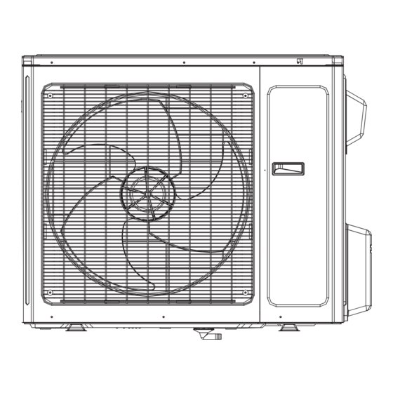
- Page 90 Step Procedure 3. Remove panel Twist off the screws connecting the panel, chassis and motor support with screwd- river, and then remove the panel. panel 4. Remove guard grille guard grille Twist off the screws fixing the guard grille and then remove the guard grille. 5.
- Page 91 Step Procedure 6. Remove right side plate right side plate Twist off the screws connecting the right side plate and chassis, valve support and condenser, and then remove the right side plate. 7. Remove electric box electric box cover Twist off the screws on electric box cover with screwdriver, and then remove the electric box cover.
- Page 92 Step Procedure electric box 1 Twist off the screws between electric box 1 and left side plate with screw- driver, pull it upwards to remove the electric box 1. 8. Remove left side plate left side plate Twist off the screws connecting the left side plate and chassis with screwdriver, and then remove the left side plate.
- Page 93 Step Procedure 10. Remove motor and motor support Twist off the tapping screws fixing the motor, pull out the pin of leading wire for motor and then remove the motor. motor motor support Twist off the tapping screws fixing the motor support, pull it upwards and then remove the motor support.
- Page 94 Step Procedure 12. Remove gas valve and liquid valve Twist off the 2 bolts fixing the valve sub-assy. Unsolder the soldering joint between gas valve and air-return pipeand then remove the gas valve.(note: when unsoldering the soldering joint, wrap the gas valve with wet cloth completely to avoid the damage to valve, and release all refrigerant completely at...
- Page 95 Step Procedure 15. Remove support plate of condenser Twist off the screws connecting the support plate of condenser and condenser with screwdriver, and then remove the support plate of condenser. support plate of condenser 16. Remove chassis and condenser Pull it upwards to separate the chassis and condenser.
- Page 96 Add: West Jinji Rd, Qianshan, Zhuhai, Guangdong, China, 519070 Tel: (+86-756) 8522218 Fax: (+86-756) 8669426 E-mail: gree@gree.com.cn www.gree.com For continuous improvement in the products, Gree reserves the right to modidy the product specification and appearance in this manual without notice and without incurring any obligations.
Need help?
Do you have a question about the GWH30LB-D3DNA3E and is the answer not in the manual?
Questions and answers