
Related Manuals for Portwell PCOM-B217VG-II


Summary of Contents for Portwell PCOM-B217VG-II
- Page 1 PCOM-B217VG-II COM Express Type II Module User's Manual Version 1.0 Copyright © Portwell, Inc., 2011. All rights reserved. All other brand names are registered trademarks of their respective owners...
-
Page 2: Table Of Contents
Preface Table of Contents How to Use This Manual Chapter 1 System Overview.......................1-1 1.1 Introduction ....................... 1-1 1.2 Check List......................1-1 1.3 Product Specification..................1-2 1.4 Mechanical Drawing..................1-3 1.5 System Architecture..................1-4 Chapter 2 Hardware Configuration ...................2-1 2.1 Jumper Setting ....................2-1 2.2 Connector Allocation.................. -
Page 3: How To Use This Manual
The content of this manual and EC declaration document is subject to change without prior notice. These changes will be incorporated in new editions of the document. Portwell may make supplement or change in the products described in this document at any time. -
Page 4: Chapter 1 System Overview
Implement PCOM-B217VG that with turbo boost can maximize CPU and graphic performance for your demand. Check List The PCOM-B217VG-II series package should cover the following basic items One PCOM-B217VG-II module board If any of these items is damaged or missing, please contact your vendor and keep all packing materials for future replacement and maintenance. -
Page 5: Product Specification
Intel 82579LM Gigabit Ethernet controller is equipped, 4 MDI pairs on Row A- B - IDE Interface Support one enhanced IDE channel with PIO mode 4 ultra DMA/33/66/100 - SATA Interface Support Two SATA 3.0 ports, Two SATA 2.0 ports - USB Interface Support eight USB 2.0 ports PCOM-B217VG-II... -
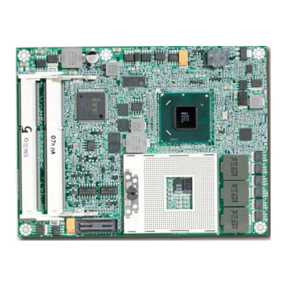
Page 6: Mechanical Drawing
System Overview Outline Dimension (L X W): 95mm (3.74”) X 125mm (4.92”) Operating Temperature: 0°C ~ 60°C (32°F ~ 140°F) Storage Temperature: -20°C ~ 80°C Relative Humidity: 5% ~ 90%, non-condensing Mechanical Drawing PCOM-B217VG-II... -
Page 7: System Architecture
System Overview System Architecture PCOM-B217VG-II... -
Page 8: Chapter 2 Hardware Configuration
( ). Jumper Setting In order to customize PCOM-B217VG-II’s features for users, in the following sections, Short means covering a jumper cap over jumper pins; Open or N/C (Not Connected) means removing a jumper cap from jumper pins. Users can refer to Figure 2-1 and Figure 2-2 for the Jumper locations. - Page 9 Hardware Configuration Figure 2-2 PCOM-B217VG-II Bottom-side Connector Location PCOM-B217VG-II...
-
Page 10: Connector Allocation
B11 GND (FIXED) C11 GND (FIXED) D11 GND (FIXED) A12 GBE0_MDI0- B12 PWRBTN# IDE_D14 IDE_IRQ A13 GBE0_MDI0+ B13 SMB_CK C13 IDE_IORDY D13 IDE_A0 A14 GBE0_CTREF B14 SMB_DAT C14 IDE_IOR# D14 IDE_A1 A15 SUS_S3# B15 SMB_ALERT# C15 PCI_PME# D15 IDE_A2 PCOM-B217VG-II... - Page 11 A52 PCIE_TX5+ B52 PCIE_RX5+ C52 PEG_RX0+ D52 PEG_TX0+ A53 PCIE_TX5- B53 PCIE_RX5- C53 PEG_RX0- D53 PEG_TX0- A54 GPI0 B54 GPO1 C54 TYPE0# D54 PEG_LANE_RV# A55 PCIE_TX4+ B55 PCIE_RX4+ C55 PEG_RX1+ D55 PEG_TX1+ A56 PCIE_TX4- B56 PCIE_RX4- C56 PEG_RX1- D56 PEG_TX1- PCOM-B217VG-II...
- Page 12 A93 GPO0 B93 VGA_HSYNC C93 GND D93 GND A94 SPI_CLK B94 VGA_VSYNC C94 PEG_RX13+ D94 PEG_TX13+ A95 SPI_MOSI B95 VGA_I2C_CK C95 PEG_RX13- D95 PEG_TX13- A96 GND B96 VGA_I2C_DAT C96 GND D96 GND A97 TYPE10# B97 SPI_CS# C97 RSVD D97 PEG_ENABLE# PCOM-B217VG-II...
- Page 13 C106 VCC_12V D106 VCC_12V A107 VCC_12V B107 VCC_12V C107 VCC_12V D107 VCC_12V A108 VCC_12V B108 VCC_12V C108 VCC_12V D108 VCC_12V A109 VCC_12V B109 VCC_12V C109 VCC_12V D109 VCC_12V A110 GND (FIXED) B110 GND (FIXED) C110 GND (FIXED) D110 GND (FIXED) PCOM-B217VG-II...
-
Page 14: Chapter 3 System Installation
Step 1 : Check all jumpers setting on proper position Step 2 : Install and configure CPU and memory module on right position Step 3 : Place PCOM-B217VG-II into the dedicated position in the system Step 4 : Attach cables to existing peripheral devices and secure it... -
Page 15: Chipset Component Driver
3.3.1 Chipset Component Driver PCOM-B217VG-II uses state-of-art Intel® QM67 chipset. It’s a new chipset that some old operating systems might not be able to recognize. To overcome this compatibility issue, for Windows Operating Systems such as Windows 2000 /XP, please install its INF before any of other Drivers are installed. -
Page 16: Intel® Active Management Technology (Intel® Amt)
Intel® Active Management Technology (Intel® AMT) Please find the latest Intel® 6.0 driver from PCOM-B217VG-II CD-title. The drivers support Windows 2000/XP/Vista/Win7. Clear CMOS Operation There is no backup battery designed on PCOM-B217VG-II, all setting will reset to default when disconnecting PCM-B217VG-II with carrier board. PCOM-B217VG-II... -
Page 17: Chapter 4 Bios Setup Information
Chapter 4 BIOS Setup Information PCOM-B217VG-II is equipped with the AMI BIOS stored in Flash ROM. These BIOS has a built-in Setup program that allows users to modify the basic system configuration easily. This type of information is stored in CMOS RAM so that it is retained during power-off periods. -
Page 18: Main
These items show the firmware of your system. Read only. System Time The time format is <Hour> <Minute> <Second>. Use [+] or [-] to configure system Time. System Date The date format is <Day>, <Month> <Date> <Year>. Use [+] or [-] to configure system Date. PCOM-B217VG-II... -
Page 19: Advanced
Use this menu to set up the items of special enhanced features. Launch PXE OpROM Enable or Disable Boot Option for Legacy Network Devices. Launch Storage OpROM Enable or Disable Boot Option for Mass Storage Devices with Option ROM PCOM-B217VG-II... - Page 20 Enables or Disables PCI Device to Generate PEER#. SERR# Generation Enables or Disables PCI Device to Generate SEER#. Relaxed Ordering Enables or Disables PCI Express Device Relaxed Ordering. Extended Tag If ENABLED allows Device to use 8-bit Tag field as a requester. PCOM-B217VG-II...
- Page 21 ASPM Support Set the ASPM Level: Force L0 – Force all links to L0 State AUTO – BIOS auto configure DISABLE – Disables ASPM Extended Synch If ENABLED allows generation of Extended Synchronization patterns. ACPI settings System ACPI Parameters. PCOM-B217VG-II...
- Page 22 The choice: Suspend Disabled, S1 (CPU Stop Clock), S3 (Suspend to RAM) Lock Legacy Resources Enables or Disable Lock of Legacy Resources. Trusted Computing Trusted Computing (TPM) settings. TPM SUPPORT Enables or Disable TPM support. O.S. will not show TPM. Reset of platform is required. PCOM-B217VG-II...
- Page 23 OS (Windows Server 2003 Sp1, Windows XP SP2, SuSE Linux 9.2 RedHat Enterprise 3 Update 3.). Hardware Prefetcher To turn on/off the Mid Level Cache (L2) streamer prefetcher. Adjacent Cache Line Prefetch To turn on/off prefetching of adjacent cache lines. PCOM-B217VG-II...
- Page 24 Time window which the long duration power is maintained. Short duration power limit Short duration power limit in Watts. SATA Configuration SATA Controller(s) Enable or disable SATA Device. SATA Mode Selection Determines how SATA controller(s) operate. The choice: IDE, AHCI, RAID PCOM-B217VG-II...
- Page 25 Active Trip Point 0 Fan Speed Active Trip Point 0 Fan Speed in percentage. Value must be between 0 (Fan off) – 100 (Max fan speed). This is the speed at which fan will run when Active Trip Point 0 is crossed. PCOM-B217VG-II...
- Page 26 The choice: 1, 2, 5, 9, 10, 14, 20 Thermal Reporting EC PEC Enable Packet Error Checking (PEC) for SMBus Block Read. DIMM1 TS READ DIMM1 Thermal Sensor Read Enable. DIMM2 TS READ DIMM2 Thermal Sensor Read Enable. 4-10 PCOM-B217VG-II...
- Page 27 Enable or disable PCH Thermal Device (D31:F6) MCH Temp Read MCH Temperature Read Enable. PCH Temp Read PCH Temperature Read Enable. CPU Energy Read CPU Energy Read Enable. CPU Temp Read CPU Temperature Read Enable. Intel TXT (LT) Configuration Intel Trusted Execution Technology. 4-11 PCOM-B217VG-II...
- Page 28 BIOS Setup Information PCH-FW Configuration Configuration Management Engine Technology Parameters. Firmware Update Configuration Configuration Management Engine Technology Parameters. 4-12 PCOM-B217VG-II...
- Page 29 Enable/Disable Intel AT in BIOS for testing only. Intel Anti-Theft Technology Recove Set the number of times Recovery attemped will be allowed. Range: 1- 64 Enter Intel AT Suspend Mode Request that platform enter Intel AT Suspend Mode. 4-13 PCOM-B217VG-II...
- Page 30 OEMFLag Bit 2: Enable/Disable MEBx selection screen. Verbose Mebx Output OEMFLag Bit 3: Enable/Disable Verbose Mebx Output. Hide Un-Configure ME Confirmation OEMFLag Bit 6: Hide Un-Configure ME without password Confirmation Prompt. MEBx Debug Message Output OEMFLag Bit 14: Enable MEBx debug message Output. 4-14 PCOM-B217VG-II...
- Page 31 Activate Remote Assistance Process Trigger CIRA boot. USB Configure Enable/Disable USB Configure function. PET Progress User can Enable/Disable PET Events progress to receive PET events or not. Intel AMT SPI Protected Enable/Disable Intel AMT SPI write protect. WatchDog Enable/Disable WatchDog Timer. 4-15 PCOM-B217VG-II...
- Page 32 The choice: 1 sec, 5 sec, 10 sec, 20 sec Device reset time-out USB mass storage device Start Unit Command time-out. The choice: 10 sec, 20 sec, 30 sec, 40 sec Device power-up delay USB mass storage device Start Unit Command time-out. 4-16 PCOM-B217VG-II...
- Page 33 BIOS Setup Information Super IO Configuration System Super IO Chip parameters. Serial Port 0 Configuration Set Parameters of Serial port 0 (COMA) 4-17 PCOM-B217VG-II...
- Page 34 Change the Serial Port mode. Select <High Speed> or <Normal mode> mode The Choice: Standard Serial Port Mode, IrDA 1.0 (HP SIR) Mode, ASKIR Mode Serial Port 0 Configuration Set Parameters of Serial port 0 (COMA) Serial Port Enable or Disable Serial Port (COM). 4-18 PCOM-B217VG-II...
- Page 35 Change the Serial Port mode. Select <High Speed> or <Normal mode> mode The Choice: Standard Serial Port Mode, IrDA 1.0 (HP SIR) Mode, ASKIR Mode Parallel Port Configuration Set Parameters of Parallel Port (LPT/LPTE) Parallel Port Enable or Disable Parallel Port (LPT/LPTE) 4-19 PCOM-B217VG-II...
- Page 36 Device Mode Change the Printer Port mode. The Choice: Standard Parallel Port Mode, EPP Mode, ECP Mode, ECP Mode & ECP mode CIR Controller Configuration Set Parameters of CIR Controller (CIR) CIR Controller Enable or Disable CIR Controller 4-20 PCOM-B217VG-II...
- Page 37 BIOS Setup Information Change Settings AUTO IO=3E0h; IRQ=10; IO=3E0h; IRQ=3, 4, 5, 6, 7, 10, 11, 12; IO=2E0h; IRQ=3, 4, 5, 6, 7, 10, 11, 12; IO=298h; IRQ=3, 4, 5, 6, 7, 10, 11, 12; H/W Monitor Monitor Hardware status 4-21 PCOM-B217VG-II...
- Page 38 Terminal VT-UTF8 is the preferred terminal type for out-of-band management. The next best choice is VT100+ and then VT100. See above, in console Redirection Settings page, for more Help with Terminal Type/Emulation. The choice: VT100, VT100+, VT-UTF8, ANSI 4-22 PCOM-B217VG-II...
- Page 39 Platform must be powered off for changes to take effect. Lock ICC registers All registers: all ICC registers will be locked. Static only – only static ICC registers will be locked. The choice: Static only, All registers 4-23 PCOM-B217VG-II...
- Page 40 BIOS Setup Information DIV-1S Integrated Clock Control options DIV-2S Integrated Clock Control options 4-24 PCOM-B217VG-II...
- Page 41 Changes will be applied permanently, starting after the next reboot. Use it to provide changes that are verified and safe. DIV-3 Integrated Clock Control options DIV-4 Integrated Clock Control options DIV-1NS Integrated Clock Control options DIV-2NS Integrated Clock Control options 4-25 PCOM-B217VG-II...
- Page 42 Long duration power limit in watts, 0 means use factory default. Long duration maintained Time window which the long duration power is maintained. Short duration power limit Short duration power limit in watts, 0 means use factory default. TCC active offset Offset from factory TCC activation temperature. 4-26 PCOM-B217VG-II...
- Page 43 BIOS Setup Information Switchable Graphics Switchable Graphics selections Sandybridge DTS Configuration Sandybridge DTS Configuration Parameters 4-27 PCOM-B217VG-II...
- Page 44 VT-d Check to enable VT-d function on MCH CHAP Device (B0:D7:F0) Enable or disable SA CHAP Device. Thermal Device (B0:D4:F0) Enable or disable SA Thermal Device. Enable NB CRID Enable or disable NB CRID WorkAround. WatchDogTimer WatchDogTimer settings. 4-28 PCOM-B217VG-II...
- Page 45 The choice: Auto, IGFX, PEG, PCI, SG Internal Graphics Keep IGD enabled based on the setup options. The choice: Auto, Disabled, Enabled GTT Size Select the GTT Size The choice: 1MB, 2MB Aperture Size Select the Aperture Size The choice: 128MB, 256MB, 512MB 4-29 PCOM-B217VG-II...
- Page 46 Select the video Device which will be activated during POST. This has no effect if external graphics present. Secondary boot display selection will appear based on your selection. VGA modes will be supported only on primary display. The choice: CRT, LVDS, HDMI/DP, DVI 4-30 PCOM-B217VG-II...
- Page 47 Int-LVDS: VBIOS enables LVDS driver by Integrated encoder. SDVO LVDS: VBIOS enables LVDS driver by SDVO encoder. eDP Port-A: LFP Driven by Int-DisplaypPort encoder from Port-A. Panel Color Depth Select the LFP Panel Color Depth The choice: 18 Bit, 24 Bit 4-31 PCOM-B217VG-II...
- Page 48 Enable or disable the control of Active State Power Management on SA side of the DMI Link. The choice: Disable, L0s, L1, L0sL1 DMI Extended Synch Control Enable DMI Extended Synchronization. DMI Gen 2 Enable or disable DMI Gen 2 4-32 PCOM-B217VG-II...
- Page 49 Configure PEG2 B0:D1:F2 Gen1-Gen2 PEG3 – Gen X Configure PEG3 B0:D6:F0 Gen1-Gen2 Always Enable PEG To enable the PEG slot. PEG ASPM Control ASPM support for the PEG Device. This has no effect if PEG is not the currently active device. 4-33 PCOM-B217VG-II...
- Page 50 Select DIMM timing profile that should be used. Memory Frequency Maximum Memory Frequency Selections in Mhz. ECC Support Enable or disable DDR ECC Support. Max TOLUD Maximum Value of TOLUD. Dynamic assignment would adjust TOLUD automatically based on largest MMIO length of installed graphic controller 4-34 PCOM-B217VG-II...
- Page 51 Enable or disable dims on channel A The choice: Enable Both DIMMs, Disable DIMM0, Disable DIMM1, Disable Both DIMMs Channel B DIMM control Enable or disable dims on channel B The choice: Enable Both DIMMs, Disable DIMM0, Disable DIMM1, Disable Both DIMMs 4-35 PCOM-B217VG-II...
- Page 52 Enable or disable routing TS-on-Board ALERT# and THERW# to EXTTS# pins on the PCH. EXTTS# via TS-on-DIMM Enable or disable routing TS-on-DIMM ALERT# to EXTTS# pin on the PCH. Virtual Temperature Sensor (VTS) Enable or disable Virtual Temperature Sensor (VTS). 4-36 PCOM-B217VG-II...
- Page 53 BIOS Setup Information GT – Power Management Control GT – Power Management Control Options RC6 (Render Standby) Check to enable render standby support. GT OverClocking Support Enable or disable GT OverClocking Support 4-37 PCOM-B217VG-II...
- Page 54 Control Detection of the Azalia device. Disable = Azalia will be unconditionally disabled Enable = Azalia will be unconditionally Enabled Auto Azalia will be enabled if present, disable otherwise. Azalia Docking Support Enable or disable Azalia Docking Support of Audio Controller. 4-38 PCOM-B217VG-II...
- Page 55 Restore AC Power Loss Select AC power state when power is re-applied after a power failure. Set NAND Management Override Option to Override NAND Management to allow driver or 3 parties software to configure the NAND module after POST. 4-39 PCOM-B217VG-II...
- Page 56 Control the USB EHCI (USB 2.0) functions. One EHCI controller must always be enabled. EHCI 2 Control the USB EHCI (USB 2.0) functions. One EHCI controller must always be enabled. USB Ports Per-Port Disable Control Control each of the USB ports (0~9) disabling. 4-40 PCOM-B217VG-II...
- Page 57 DMI Link ASPM Control The control of Active State Power Management on both NB side and SB side of the DMI Link DMI Link Extended Synch Control The control of Extended Synch on SB side of the DMI Link 4-41 PCOM-B217VG-II...
- Page 58 : DISABLE – Disables ASPM Enable or disable PCI Express Unsupported Request Reporting. Enable or disable PCI Express Device Fatal Error Reporting. NFER Enable or disable PCI Express Device Non-Fatal Error Reporting. Enable or disable PCI Express Device Correctable Error Reporting. 4-42 PCOM-B217VG-II...
- Page 59 Set the ASPM Level: Force L0 – Force all links to L0 state : AUTO – BIOS auto configure : DISABLE – Disables ASPM Enable or disable PCI Express Unsupported Request Reporting. Enable or disable PCI Express Device Fatal Error Reporting. NFER Enable or disable PCI Express Device Non-Fatal Error Reporting. 4-43 PCOM-B217VG-II...
- Page 60 Set the ASPM Level: Force L0 – Force all links to L0 state : AUTO – BIOS auto configure : DISABLE – Disables ASPM Enable or disable PCI Express Unsupported Request Reporting. Enable or disable PCI Express Device Fatal Error Reporting. 4-44 PCOM-B217VG-II...
- Page 61 Reserved I/O (4K/8K/12K/16K/20K) Range for this Root Bridge PCI Express Root Port 4 Control the PCI Express Root Port. ASPM Support Set the ASPM Level: Force L0 – Force all links to L0 state : AUTO – BIOS auto configure : DISABLE – Disables ASPM 4-45 PCOM-B217VG-II...
- Page 62 Extra Bus Reserved (0-7) for bridges behind this Root Bridge. Reserved Memory Reserved Memory and prefetchable Memory (0-20MB) Range for this Root Bridge Reserved I/O Reserved I/O (4K/8K/12K/16K/20K) Range for this Root Bridge PCI Express Root Port 5 Control the PCI Express Root Port. 4-46 PCOM-B217VG-II...
- Page 63 Enable or disable PCI Express Hot Plug. Extra Bus Reserved Extra Bus Reserved (0-7) for bridges behind this Root Bridge. Reserved Memory Reserved Memory and prefetchable Memory (0-20MB) Range for this Root Bridge Reserved I/O Reserved I/O (4K/8K/12K/16K/20K) Range for this Root Bridge 4-47 PCOM-B217VG-II...
- Page 64 Enable or disable PCI Express PME SCI. Hot Plug Enable or disable PCI Express Hot Plug. Extra Bus Reserved Extra Bus Reserved (0-7) for bridges behind this Root Bridge. Reserved Memory Reserved Memory and prefetchable Memory (0-20MB) Range for this Root Bridge 4-48 PCOM-B217VG-II...
- Page 65 Enable or disable Root PCI Express System Error on Correctable Error. PME SCI Enable or disable PCI Express PME SCI. Hot Plug Enable or disable PCI Express Hot Plug. Extra Bus Reserved Extra Bus Reserved (0-7) for bridges behind this Root Bridge. 4-49 PCOM-B217VG-II...
- Page 66 Reserved I/O (4K/8K/12K/16K/20K) Range for this Root Bridge Boot Configuration Setup Prompt Timeout Number of seconds to wait for setup activation key. 65535(0xFFFF) means indefinite waiting. Boot NumLock State Select the keyboard NumLock state Quiet Boot Enable or disable Quiet Boot option 4-50 PCOM-B217VG-II...
- Page 67 Option ROM Messages Set display mode for Option ROM Interrupt 19 Capture Enable: Allows Option ROMs to trap Int 19 Boot Option #1 Sets the system boot order Security Administrator Password Set Setup Administrator Password User Password Set User password 4-51 PCOM-B217VG-II...
- Page 68 Reset the system without saving the changes. Save Changes Save Changes done so far to any of the setup options. Discard Changes Discard Changes done so far to any of the setup options. Restore Defaults Restore/Load Default Values for all the setup options. 4-52 PCOM-B217VG-II...
- Page 69 Save the changes done so far as User Defaults. Restore User Defaults Restore the User Defaults to all the setup options. Lanch EFI Shell from filesystem device Attempts to Launch EFI Shell application (Shellx64.efi) from one of the available filesystem devices 4-53 PCOM-B217VG-II...
-
Page 70: Chapter 5 Troubleshooting
BIOS setting that Portwell has highly endorsed. As a matter of fact, users can load the default BIOS setting any time when system appears to be unstable in boot up sequence. - Page 71 Hard Disk Event IRQ 15 Usable IRQ 【Unassigned】 It is then very easy to find out which IRQ resource is ready for additional peripherals. If IRQ resource is not enough, please disable some devices listed above to release further IRQ numbers. PCOM-B217VG-II...
-
Page 72: System Memory Address Map
Program Area 0F6C-9BBF 561K 【Available】 First Meg -- Conventional memory end at 623K -- 9BC0-9CFF Extended BIOS Area 9D00-9FFF Unused A000-AFFF VGA Graphics B000-B7FF Unused B800-BFFF VGA Text C000-CFBF Video ROM CFC0-EFFF 133K Unused F000-FFFF System ROM First 64K Extended PCOM-B217VG-II...
Need help?
Do you have a question about the PCOM-B217VG-II and is the answer not in the manual?
Questions and answers