Advertisement
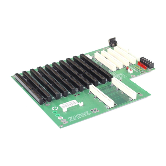
PBP-14P4
he PBP-14P4 backplane is fully PICMG Rev 2.1 compliant. It is a member of
T
PBP's PCI product family and is intended to support all PICMG compliant
boards on the market.
Introduction
Traditional PC is outstanding with the all-in-one facility, in which processor seat,
chipset, memory sockets, ISA/PCI slots, device and power connectors are
accommodated over a single PCB. This would absolutely draw the limitation line on
multiple peripheral cards adopti on as well as the timing needed for board
replacement in the event of system failure. The new generation industrial PC has
made a new platform with a combination of two parts – SBC and backplane.
Different from traditional motherboards, industrial PC features on easily removable
SBC as the working board that has PICMG or ISA form factor so that users may
easily apply or remove the SBC from the system. Reducing the system down time is
obviously visible. Backplane is hence designed with PICMG slots to hold the SBC as
a system. Some backplanes also have ISA/PCI slots to hold ISA/PCI peripheral
cards. This design has been proved successful to provide far more PCI slots than
traditional motherboard could ever holds (4 PCI slots) to meet the requirement of
current technology and market demands, especially in CTI market.
As a matter of fact, with the needs from industrial PC users moving on, applications
with SBC and backplane have been fully required and are currently leading the
industrial PC market.
Design Philosophy
Our backplane is designed to meet customer's demand. Better power distribution,
thick PCB with more ruggedness, and user-friendly designed are the key design
routes. We hold the remind to produce backplane of trustable quality throughout the
design phases, and this is how our backplane is made and presented.
In order to keep good power filtering and avoid fire explosion, Electrolytic capacitor
and Ceramic capacitor are used to replace traditional Tantalum capacitor. All our
backplane models have 4 l a yers with separate power layer and ground layer to
reduce power noise. Assorted connectors, including keyboard connectors and power
connectors, are provided for easy installation and expansion. All backplanes models
are made to meet industrial grade environment requirement (temperature, humidity,
etc.).
As a matter of fact, with the needs from industrial PC users moving on, applications
with SBC and backplane have been fully required and are currently leading the
industry market.
PRC-4184 User's Manual
Arrow.com.
Downloaded from
8 ISA/ 4 PCI/ 2 PICMG Passive Backplane
17
Advertisement
Table of Contents

Related Manuals for Portwell PBP-14P4


Summary of Contents for Portwell PBP-14P4
- Page 1 PBP-14P4 8 ISA/ 4 PCI/ 2 PICMG Passive Backplane he PBP-14P4 backplane is fully PICMG Rev 2.1 compliant. It is a member of PBP’s PCI product family and is intended to support all PICMG compliant boards on the market. Introduction...
-
Page 2: Product Features
Product Features Two PCI/ISA slots for the CPU board Connector Eight ISA slots for full-sized ISA boards Four 5V 32-bit PCI slots for full-sized boards on the Primary bus. The ID Select of these slots are configurable through jumpers One AT standard power connector: 12 pins, 5A max. per pin for +5V, -5V, +12V, -12V voltages and Ground One ATX standard power connector: 20 pins, 5A max. -
Page 3: Jumpers And Connectors
Board Drawing Jumpers and Connectors JUMPER/ CONNECTOR DESCRIPTION PCI A,B PICMG connectors ISA 7, 10 PCI1-4 32-BIT PCI BUS connectors (primary) KB1, KB2, KB3 Keyboard connector CN1, CN2 Fan connector Power extension pins ATX power connector P8/P9 power connector Power extension terminal block ATX P/S control connector PRC-4184 User’s Manual Arrow.com. -
Page 4: Pin Assignment
Pin Assignment CN5 (P8 / P9) CN4 (ATX) NAME NAME NAME +3.3V +3.3V +3.3V -12V +12V -12V PS-ON PWR-OK 5V STB +12V CN6 (Power Extension) CN7 (For ATX PSU only) NAME NAME NAME +12V PW-OK +12V @ 5A 5VSB +5V @ 5A PS-ON -12V @ 0.5A *Note: If you are using a non-ATX... - Page 5 Power Supply 1. If you use AT power supply, please apply the P8/P9 connector over CN5 (Fig. 2). If your use ATX power supply, please apply the 20-pin ATX power connector over CN4 (Fig. 3). Besides, you need to apply one 4-pin ATX power control cable between your SBC and backplane over the 4-pin header CN7.
- Page 6 2. If you use a PS/2 keyboard, simply apply them over the PS/2 connector on your SBC. In this application, the 5-pin keyboard control connector is not required (Fig. 7). Fig. 7 Chassis Make sure the copper lifting stands are placed below all the mounting holes of your backplane.
Need help?
Do you have a question about the PBP-14P4 and is the answer not in the manual?
Questions and answers