
Subscribe to Our Youtube Channel
Related Manuals for Digisol DG-WM2005SI


Summary of Contents for Digisol DG-WM2005SI
-
Page 1: User Manual
DG-WM2005SI User Manual DG-WM2005SI 300Mbps CEILING MOUNT ACCESS POINT User Manual V1.0 2014-05-14 As our products undergo continuous development the specifications are subject to change without prior notice... -
Page 2: Table Of Contents
DG-WM2005SI User Manual Table of contents 1. INTRODUCTION ............................6 1.1 P ..........................6 ACKAGE ONTENTS 1.2 H ......................... 8 ARDWARE NSTALLATION 1.2.1 WARNING ............................8 1.2.2 SYSTEM REQUIREMENTS ......................8 1.2.3 Hardware Configuration ....................... 10 1.2.4 Mounting on the Ceiling / Wall ...................... 11 1.2.5 LED Indicators .......................... - Page 3 DG-WM2005SI User Manual 3.3 S ..............................53 YSTEM 3.3.1 System Information ........................54 3.3.2 System Status ..........................54 3.3.2.1 Web Log ............................... 54 3.3.2.2 Syslog ..............................55 3.3.2.3 Email Alert ............................55 3.3.3 System Tools ..........................56 3.3.3.1 Change Password ..........................56 3.3.3.2 FW Upgrade ............................
- Page 4 Trademarks: DIGISOL™ is a trademark of Smartlink Network Systems Ltd. All other trademarks are the property of the respective manufacturers. FCC Interference Statement This equipment has been tested and found to comply with the limits for a Class B digital device pursuant to Part 15 of the FCC Rules.
-
Page 5: Ce Declaration Of Conformity
DG-WM2005SI User Manual CE Declaration of Conformity This equipment complies with the requirements relating to electromagnetic compatibility, EN 55022/A1 Class B. -
Page 6: Introduction
DG-WM2005SI User Manual 1. Introduction Congratulations on your purchase of this outstanding product: APC772-001 WiFi 2.4G N 300 Ceiling Access Point are designed for small- and medium-sized businesses to extend the existing wired networks and has the ability to operate in different modes and can be used in a wide variety of wireless applications like AP, Point-to-Point. - Page 7 DG-WM2005SI User Manual 1 No. RJ45 Cable Installation Guide CD 1 No.
-
Page 8: Hardware Installation
DG-WM2005SI User Manual 1.2 Hardware Installation 1.2.1 WARNING Do not use the product in high humidity or high temperatures. Do not use the same power source for the Product as other equipment. Only use the power adapter that comes with the package. Using a different voltage rating power adaptor may damage the device. - Page 9 DG-WM2005SI User Manual higher) Windows® Users: Make sure you have the latest version of Java installed. Visit www.java.com to download the latest version. Computer with the following: • Windows® 7, Vista®, or XP with Service Pack 2 CD Installation Wizard Requirements •...
-
Page 10: Hardware Configuration
DG-WM2005SI User Manual 1.2.3 Hardware Configuration Rear View: PoE-PD Receptor Ethernet for Power Port Adapter... -
Page 11: Mounting On The Ceiling / Wall
DG-WM2005SI User Manual 1.2.4 Mounting on the Ceiling / Wall This device is designed for easily mounted on the ceiling or wall with a simple mount bracket. Before mounting it to the expected location, please make proper configuration for the device setting and run the PoE Ethernet cable to the location in advance. - Page 12 DG-WM2005SI User Manual Plug-in the cable (Ethernet cable, Power cord) to the connectors in the button side. Run the cables upward to proper location. Attached this device to mounting bracket by rotating it clock wisely to click into place. Installation completed.
-
Page 13: Led Indicators
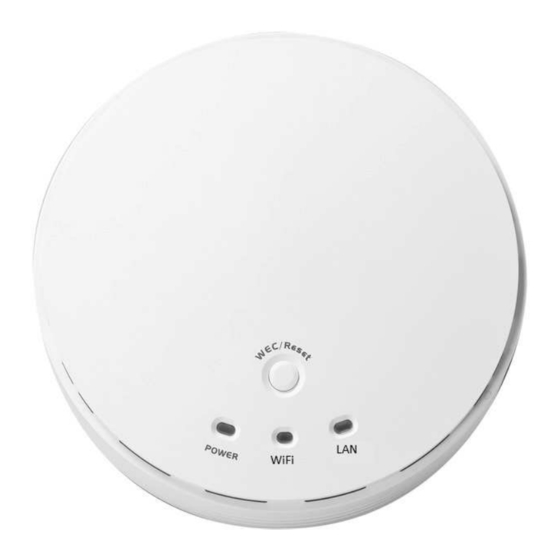
DG-WM2005SI User Manual 1.2.5 LED Indicators Description When the device is booted up and ready: When WEC/Reset is triggered (with button pressed): Status LED flashes at different rate according button-pressed duration. Stage 1 (1 ~ 5 sec) : Flash very fast... - Page 14 DG-WM2005SI User Manual Solid Green: Ethernet connection is linked up. Flash Green: Data packet is transferred over the Ethernet link.
-
Page 15: Button Definition
DG-WM2005SI User Manual 1.2.6 Button Definition There is one multi-function push button “WEC/Reset” in this device. According to different button pressed duration, the device will take specific reaction. For ease of interacting with the device, you can also check the Status and WiFi LED to determine when to release the button. The Reset/WEC button’s behavior is defined below:... - Page 16 DG-WM2005SI User Manual Besides the above “Master to Slave” configuration, the easy configuration process also supports “Slave to Slave” configuration. Press the WEC/Reset button of the first Slave AP (say Slave1 that has been paired and configured) for 1~3 seconds, release it to trigger the WEC process. Then, the WiFi LED flashes fast.
- Page 17 DG-WM2005SI User Manual Press the WEC/Reset button for about 11~15 seconds and release it. Reset Slave WEC/Reset The Slave AP will be marked as an un-configured Configuration (Press 13 sec) device, so that it can be paired with another Master or configured Slave AP later.
-
Page 18: Getting Started
DG-WM2005SI User Manual 2. Getting Started Before you can install this product to designated location and make it operate properly, you have to configure the device setting to fit in your network environment. Hardware Preparation: a. Connect an Ethernet cable between this device and the computer that you will operate to set up the device. -
Page 19: Easy Setup Via Web Ui
DG-WM2005SI User Manual Referring to Appendix A, and set the TCP/IPv4 address of your computer to 192.168.123.25, and subnet mask to 255.255.255.0. After applying this setting, you can now access to the web UI for configuring the device. Easy Setup via Web UI You can browse web UI to configure the device. - Page 20 DG-WM2005SI User Manual Type the default password “admin” in the system authentication fields, and then click ‘login’ button. Select your language. Select “Wizard” for basic settings in a simple way. Or, you can go to Basic Network / Advanced Network / Applications / System to setup the...
- Page 21 DG-WM2005SI User Manual Press “Next” to start the Setup Wizard. Configure with the Setup Wizard Step 1 You can change the password of administrator here. Step 2 LAN IP Address. You have to change the IP address of this device...
- Page 22 DG-WM2005SI User Manual Wireless settings. Specify VAP1’s wireless authentication and encryption. Step 4 Check the information again. Step 5 System is applying the setting. Step 6 Click finish to complete it.
-
Page 23: Use Wec Button To Setup Wireless Profiles
DG-WM2005SI User Manual Use WEC Button to Setup Wireless Profiles WEC (Wireless Easy Connection) is an easy configuration feature that is similar to well-known WPS function. It can be used to duplicate one device’s wireless configuration to the other AP devices from the same manufacture by clicking one button for both devices. - Page 24 DG-WM2005SI User Manual Step Button Description 1. Make sure AP1 is in Master Mode (WiFi LED should be “Green” color, if not, you have to toggle its AP mode via pressing the WEC button for Set AP1 in Master Mode, 9~10 seconds) and configure it via web UI.
-
Page 25: One Master And A Series Of Connected Slaves
DG-WM2005SI User Manual Master AP AP1. 3. Install AP3 to its location and verify its wireless network connectivity with a client device (Client1) at the location beyond the service range of AP1. In this case, AP3 is located out of the service range of AP1, you don’t have to check AP3’s WiFi LED,... - Page 26 DG-WM2005SI User Manual Step Button Description Make sure AP1 is in Master Mode (WiFi LED should be “Green” color, if not, you have to toggle its AP Set AP1 in Master Mode, mode via pressing the WEC button for 8 seconds) and configure it via web UI.
- Page 27 DG-WM2005SI User Manual expected locations. Install AP2 to its location and verify its wireless network connectivity with a client device at the location beyond the service range of AP1. Besides, You can also check the AP2’s WiFi LED, it should be “Solid Amber” if AP2 already connected a Master AP AP1.
-
Page 28: Making Configurations
DG-WM2005SI User Manual 3 Making Configurations Whenever you want to configure your network or this device, you can access the Configuration Menu by opening the web-browser and typing in the IP Address of the device. The default IP Address is: 192.168.123.50. In the configuration section you may want to check the connection status of this device, to do Basic or Advanced Network setup or to check the system status. - Page 29 DG-WM2005SI User Manual Note: You can see the Connection Status screen below after you logged in. Note : You can see all the status of this device in the ‘ ‘ ‘ ‘ Status’ ’ ’ ’ main menu section.
-
Page 30: Basic Network
DG-WM2005SI User Manual Basic Network You can enter Basic Network for Ethernet LAN, Wireless and IPv6 settings in this web page. 3.1.1 Ethernet LAN... -
Page 31: Wireless
DG-WM2005SI User Manual 1. Device Network Type: This device supports two network types for connecting to your local network. Static IP: Allow a device to act as a Static host. If you need Static host and please entry IP Address. -
Page 32: Wireless Setup
DG-WM2005SI User Manual The embedded RF Module1/Wireless is a IEEE 802.11b/g/n compliant 2.4GHz Wireless Module. 3.1.2.1 Wireless Setup There are several wireless operation modes provided by this device. They are: “AP Only Mode”, “WDS Hybrid Mode”, “WDS Only Mode”, and “Universal Repeater Mode”. You can choose the expected mode and configure the device manually. - Page 33 DG-WM2005SI User Manual 1. Wireless Module: Enable the wireless function. 2. Wireless Operation Mode: Choose “AP Only Mode” from the list. 3. Green AP: Enable the Green AP function to reduce the power consumption when there is no wireless traffic.
- Page 34 DG-WM2005SI User Manual scanned by wireless clients. Those who know the SSID can manually specify the SSID on their client device to connect the hidden wireless network. VLAN ID: This device supports mapping of a SSID to a certain VLAN ID to separate workgroups across wireless and wired domains.
- Page 35 DG-WM2005SI User Manual In this mode, you can only choose “None” or “WEP” in the encryption field. Shared Shared key authentication relies on the fact that both stations taking part in the authentication process have the same "shared" key or passphrase. The shared key is manually set on both the client station and the AP.
-
Page 36: Wds Hybrid Mode
DG-WM2005SI User Manual and port number for the RADIUS Server, and then fill in 64 hexadecimal (0, 1, 2…8, 9, A, B…F) digits, or 8 to 63 ASCII characters as the shared key. The key value is shared by the RADIUS server and this router. This key value must be consistent with the key value in the RADIUS server. - Page 37 DG-WM2005SI User Manual 1. Lazy Mode: This device support the Lazy Mode to automatically learn the MAC address of WDS peers, you don’t have to input other peer AP's MAC address. However, not all the APs can be set to enable the Lazy mode simultaneously; at least there must be one AP with all the WDS peers’...
- Page 38 DG-WM2005SI User Manual clients can know how many AP devices by scanning the network. Therefore, if this setting is configured as “Disable”, you can hide the wireless network from been scanned by wireless clients. Those who know the SSID can manually specify the SSID on their client device to connect the hidden wireless network.
- Page 39 DG-WM2005SI User Manual In this mode, you can only choose “None” or “WEP” in the encryption field. Shared Shared key authentication relies on the fact that both stations taking part in the authentication process have the same "shared" key or passphrase. The shared key is manually set on both the client station and the AP.
-
Page 40: Wds Only Mode
DG-WM2005SI User Manual 3.1.2.1.3 WDS Only Mode WDS (Wireless Distributed System) function let APs acts as a wireless LAN bridge. All stations associated with WDS APs could see each other and roam through APs without changing WiFi configurations. You can use this feature to build up a large wireless network in... - Page 41 DG-WM2005SI User Manual 1. Lazy Mode: This device support the Lazy Mode to automatically learn the MAC address of WDS peers, you don’t have to input other peer AP's MAC address. However, not all the APs can be set to enable the Lazy mode simultaneously; at least there must be one AP with all the WDS peers’...
- Page 42 DG-WM2005SI User Manual authentication request by the client that contains the station ID (typically the MAC address). This is followed by an authentication response from the AP containing a success or failure message. An example of when a failure may occur is if the client's MAC address is explicitly excluded in the AP’s configuration.
-
Page 43: Universal Repeater Mode
DG-WM2005SI User Manual 3.1.2.1.4 Universal Repeater Mode Universal Repeater is a technology used to extend wireless coverage. It provides the function to act as Adapter (Client) and AP at the same time and can use this function to connect to a Root AP and use AP (SSID name must be the same as that of Root AP) function to service all wireless stations within its coverage. - Page 44 DG-WM2005SI User Manual 1. Green AP: Enable the Green AP function to reduce the power consumption when there is no wireless traffic. 2. Network ID (SSID): Network ID is used for identifying a Wireless LAN. Client stations can roam freely over this device and other Access Points that have the same Network ID.
-
Page 45: Advanced Wireless Setup
DG-WM2005SI User Manual 3.1.3 Advanced Wireless Setup This device provides advanced wireless setup for professional user to optimize the wireless performance under the specific installation environment. 3.1.3.1 Advanced RF Module1/Wireless Settings 1. Beacon interval: Beacons are packets sent by a wireless router to synchronize wireless devices. - Page 46 DG-WM2005SI User Manual broadcast or multicast messages for associated clients, it sends the next DTIM with a DTIM Interval value. 6. WMM Capable: WMM can help control latency and jitter when transmitting multimedia content over a wireless connection. 7. WLAN Partition: You can check the WLAN Partition function to separate the wireless clients associated to the same VAP.
-
Page 47: Ipv6
DG-WM2005SI User Manual 3.1.4 IPv6 The growth of the Internet has created a need for more addresses than are possible with IPv4. IPv6 (Internet Protocol version 6) is a version of the Internet Protocol (IP) intended to succeed IPv4, which is the protocol currently used to direct almost all Internet traffic. IPv6 also implements additional features not present in IPv4. -
Page 48: Advanced Network
DG-WM2005SI User Manual Advanced Network This device also supports other advanced network features for you to further manage the device. You can finish the configuration for Firewall, and Management in this section. -
Page 49: Firewall
DG-WM2005SI User Manual 3.2.1 Firewall 3.2.1.1 MAC Address Control MAC Address Control allows you to assign different access right for different users and to assign a specific IP address to a certain MAC address. 1. MAC Address Control: Check “Enable” to enable the “MAC Address Control”. All of the settings in this page will take effect only when “Enable”... -
Page 50: Management
DG-WM2005SI User Manual 3.2.2 Management 3.2.2.1 UPNP UPnP Internet Gateway Device (IGD) Standardized Device Control Protocol is a NAT port mapping protocol and is supported by some Network device. It is a common communication protocol of automatically configuring port forwarding. Applications using peer-to-peer networks, multiplayer gaming, and remote assistance programs need a way to communicate through home and business gateways. -
Page 51: Snmp
DG-WM2005SI User Manual 3.2.2.2 SNMP In brief, SNMP, the Simple Network Management Protocol, is a protocol designed to give a user the capability to remotely manage a computer network by polling and setting terminal values and monitoring network events. - Page 52 DG-WM2005SI User Manual 1. Enable SNMP: Enable this Function. 2. SNMP Version: Supports SNMP V1, V2c, and V3. 3. Get Community: The community of GetRequest that this device will respond. This is a text password mechanism that is used to weakly authenticate queries to agents of managed network devices.
-
Page 53: System
DG-WM2005SI User Manual Trap message to the management PCs consequently. Afterwards, click on “Save” to store your settings or click “Undo” to give up the changes. System In this section you can see system information, system logs, use system tools for system update... -
Page 54: System Information
DG-WM2005SI User Manual 3.3.1 System Information You can view the System Information in this page. 3.3.2 System Status 3.3.2.1 Web Log Log Types: You can select the log types to be collected in the web log area. There are “System”, “Attacks”, “Drop”, and “Debug” types for you to select. -
Page 55: Syslog
DG-WM2005SI User Manual 3.3.2.2 Syslog This device also can export system logs to specific destination by means of syslog (UDP) and SMTP(TCP). With enabled Syslog function, this device will send log to a certain host periodically. You need to install a syslog utility on a host to receive syslogs. -
Page 56: System Tools
DG-WM2005SI User Manual This device can also export system logs via sending emails to specific recipients. The items you have to setup include: Setting of Email alert: Check if you want to enable Email alert (send syslog via email). SMTP Server: Port: Input the SMTP server IP and port, which are connected with ':'. If you do not specify port number, the default value is 25. -
Page 57: Fw Upgrade
DG-WM2005SI User Manual 3.3.3.2 FW Upgrade If new firmware is available, you can upgrade device firmware through the WEB GUI here Press “browse” button to indicate the file name of new firmware, and then press Upgrade button to start to upgrade new firmware on this device. If you want to upgrade a firmware which is from GPL policy, please check “Accept unofficial firmware”. -
Page 58: System Time
DG-WM2005SI User Manual 3.3.3.3 System Time If new firmware is available, you can upgrade device firmware through the WEB GUI here. Time Zone: Select a time zone where this device locates. Auto-Synchronization: Check the “Enable” checkbox to enable this function. Besides, you can select a NTP time server to consult UTC time. -
Page 59: Others
DG-WM2005SI User Manual 3.3.3.4 Others In this section you can do system backup, reset to default, system reboot settings and ping test. Backup Setting: You can backup your settings by clicking the “Backup” button and save it as a bin file. Once you want to restore these settings, please click Firmware Upgrade button and use the bin file you saved. -
Page 60: Mmi
DG-WM2005SI User Manual 3.3.4 MMI 3.3.4.1 Web UI You can set UI administration time-out duration in this page. If the value is “0”, means the time-out is unlimited. -
Page 61: Troubleshooting
DG-WM2005SI User Manual 4 Troubleshooting This Chapter provides solutions to problems for the installation and operation of the WiFi Concurrent N300 Business AP. You can refer to the following if you are having problems. Why can’t I configure the device even the cable is plugged and the LED is lit? - Page 62 DG-WM2005SI User Manual properly. Network adapter names will vary depending on your specific adapter. The installation steps listed below are applicable for all network adapters. Go to Start > Right click on “My Computer” > Properties. Select the Hardware Tab.
- Page 63 DG-WM2005SI User Manual III. Disable all security settings such as WEP, and MAC Address Control. IV. Turn off the WiFi Concurrent N300 Business AP and the client, then restart it and then turn on the client again. V. Ensure that the LEDs are indicating normally. If not, make sure that the power and Ethernet cables are firmly connected.
- Page 64 DG-WM2005SI User Manual Try changing the channel on the WiFi Concurrent N300 Business AP, and your Access Point and Wireless adapter to a different channel to avoid interference. III. Keep your product away from electrical devices that generate RF noise, like microwaves, monitors, electric motors, etc.
-
Page 65: Appendix A. Assigning A Static Ip In Windows Pc
DG-WM2005SI User Manual Appendix A. Assigning a Static IP in Windows PC When organizing your local network it’s easier to assign each computer it’s own IP address than using DHCP. Here we will take a look at doing it in XP, Windows 7, Windows 8 and Windows 8.1. - Page 66 DG-WM2005SI User Manual Then when the Network and Sharing Center opens, click on Change adapter settings. This will be the same on Windows 7 or 8.x.
- Page 67 DG-WM2005SI User Manual Right-click on your local adapter and select Properties. In the Local Area Connection Properties window highlight Internet Protocol Version 4 (TCP/IPv4) then click the Properties button.
- Page 68 DG-WM2005SI User Manual Now select the radio button Use the following IP address and enter in the correct IP, Subnet mask, and Default gateway that corresponds with your network setup. Then enter your Preferred and Alternate DNS server addresses. Here we’re on a home network and using a simple Class C network configuration and Google DNS.
- Page 69 DG-WM2005SI User Manual Now close out of the Local Area Connections Properties window.
- Page 70 DG-WM2005SI User Manual Windows 7 will run network diagnostics and verify the connection is good. Here we had no problems with it, but if you did, you could run the network troubleshooting wizard. Now you can open the command prompt and do an ipconfig to see the network adapter settings have been successfully changed.
- Page 71 DG-WM2005SI User Manual Right-click on the adapter you want to set the IP for and select Properties. Highlight Internet Protocol (TCP/IP) and click the Properties button.
- Page 72 DG-WM2005SI User Manual Now change the IP, Subnet mask, Default Gateway, and DNS Server Addresses. When you’re finished click OK.
- Page 73 DG-WM2005SI User Manual You will need to close out of the Network Connection Properties screen before the changes go into effect.
- Page 74 DG-WM2005SI User Manual Again you can verify the settings by doing an ipconfig in the command prompt. In case you’re not sure how to do this, click on Start then Run. In the Run box type in cmd and click OK.
-
Page 75: Warranty Information
DG-WM2005SI User Manual Then at the prompt type in ipconfig and hit Enter. This will show the IP address for the network adapter you changed. If you have a small office or home network, assigning each computer a specific IP address makes it a lot easier to manage and troubleshoot network connection problems.
Need help?
Do you have a question about the DG-WM2005SI and is the answer not in the manual?
Questions and answers