Advertisement
Quick Links
Advertisement

Related Manuals for Extreme Flight 120cc SLICK 580 EXP


Summary of Contents for Extreme Flight 120cc SLICK 580 EXP
- Page 1 120cc SLICK 580 Assembly Manual Copyright 2017 Extreme Flight RC...
- Page 2 If you are not willing to accept ALL liability for the use of this product, please return it to the place of purchase immediately. Extreme Flight RC, Ltd. guarantees this kit to be free of defects in materials and workmanship for a period of 30 DAYS from the date of purchase. All warranty claims must be accompanied by the original dated receipt.
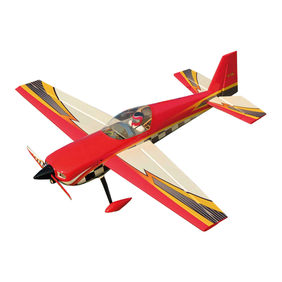
- Page 3 Congratulations on your purchase of the Extreme Flight RC 120cc Slick 580 EXP! Designed by Extreme Flight and developed by Jase Dussia, the Slick 580 was conceived as a no holds barred, no excuses all out Freestyle competition machine. The first prototypes were sent directly to the Dussia's in Michigan in the Summer of 2016.
- Page 4 1 x Extreme Flight 1.5" single aluminum servo arm for rudder if using single rear mounted servo 1 x Extreme Flight 4” double offset aluminum arm for the rudder if using pull pull rudder setup. 2 x 6” Extreme Flight 20 AWG Servo Extensions for inboard aileron servo 3 X 24"...
- Page 5 Your flying experience will be greatly enhanced once your plane is properly dialed in. 7. Extreme Flight now has their own Vimeo channel. There are many assembly videos providing extreme detail on certain aspects of the...
- Page 6 Let's Begin: 1. Locate the wing panels/ailerons and horizontal stabilizers/elevators and associated hardware bags. We will begin by hinging all of these at one time. I strongly recommend 30 minute (or slower curing) epoxy for installing hinges. I have found it easier to apply 3-5 drops of glue in the hinge hole and then using a toothpick, or similar, spread the glue around the sides of the hinge hole.
- Page 7 2. Install the control horns for the ailerons. ***PLEASE NOTE*** There are 2 different size control horns for the ailerons. The 2 longer sets are for the outboard aileron servos, the 2 shorter sets are for the inboard locations. Pay very close attention when separating and grouping the horns to be sure you are gluing the correct horns in the correct location! Insert the horns into the base plate and then temporarily install them in the...
- Page 9 3. Install the aileron servos and orient the output shaft of the servo towards the hinge line. You will notice there are 2 types of ball links included: one standard ball link and one with a built in riser. The standard ball link is sandwiched between the control horns, the ball link with the riser is secured to the aluminum servo arm.
- Page 11 4. Install the elevator servos, orient the output shaft toward the hinge line of the horizontal stabilizer. It will be easier to install the servo arms after mounting the servo. Make all hookups for the pushrods/ball links as we did in the previous step.
- Page 13 6. Next we will install the main landing gear, axles, tires, wheel pants and wheel cuffs. Use the provided bolts, washers and nuts from the main landing gear hardware kit to mount the carbon gear to the fuselage.
- Page 15 7. Slide the landing gear cuffs into place against the fuselage and secure with Goop style silicon glue. Tape in place until glue is fully cured. 8. Insert the axles into the holes on the landing gear leg and secure with a washer and lock nut.
- Page 17 9. Next we will install the tailwheel. Notice there is a 3mm hole in the bottom of the rudder about 3" inches from the hinge line. Remove the covering over this hole and then glue the included ball link into this hole with epoxy. You will also notice that the mounting plate for the tailwheel assembly is recessed.
- Page 19 10. Next we'll install the engine. There are laser marked locations to drill if using the DA-120. There is also a laser scribed cross to use a template for other engine makes. Drill for 1/4x20 mounting bolts at the proper locations. 11.
- Page 20 12. The following picture shows the location I mounted my throttle servo as well as the mufflers installed. Use a rotary tool to open the bottom of the cowl to fit the mufflers and to provide an exit for air. Notice I've also made a hole so that I can reach the choke lever easily with my finger.
- Page 22 13. A set of engine baffles has been provided to duct air over the engine cylinders. These will need to be trimmed to fit your chosen engine. Glue in place with Goop or epoxy. 14. Mount the cowl using the 3 3mm socket head cap screws and washers. The longest of the 3 bolts is used to secure the bottom of the cowl and the remaining bolts secure the top of the cowl as shown.
- Page 23 15. Secure your choice of tank to the tank tray over the carbon wing tube with Velcro or cable ties. We used the EF Flowmaster 34 ounce tank and fuel tubing along with an EF fuel dot. There is a laser cut hole in each side of the fuselage to install the EF fuel dot.
- Page 24 16. When preparing the Slick for flight, slide the stab tube into the socket in the rear of the model. Slide the stab onto the tube and secure the servo lead to the servo extension with heat shrink tubing (or an EF servo safety clip as shown if you plan to remove the stabs for transport).
- Page 25 17. Slide the wing tube into the fuselage socket and slide the wings onto the tube. Connect the aileron servo extensions to the receiver (this is where the EF mutli-plug is of great benefit, please see picture). 18. Secure the wing using 4 4mm bolts and washers inserted into the mounting tabs extending from the root of the wings.
- Page 26 19. A set of SFGs and wing tips are included. They are secured with 3 mm bolts. We suggest you experiment with each configuration and decide which works best for your flying style. Attaching the racing wing tips will slow the roll rate slightly which some flyers may find beneficial.
- Page 27 I get the planes to look so shiny, this is my secret. You may wish to apply all of your graphics before applying the coat of wax. Thanks again for your purchase of the Extreme Flight RC 120cc Slick 580 EXP. I hope you enjoy assembling and flying yours as much as I have mine.
Need help?
Do you have a question about the 120cc SLICK 580 EXP and is the answer not in the manual?
Questions and answers