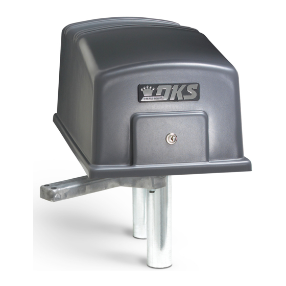
DKS Series 6050 Owner's Manual
Vehicular swing gate opener
Hide thumbs
Also See for Series 6050:
- Owner's manual (42 pages) ,
- Quick start (2 pages) ,
- Installation & owner's manual (42 pages)
Table of Contents
Advertisement
Quick Links
Installation/Owner's Manual
Use this manual for circuit board 4502-010 Revision K or higher.
For operators manufactured July 2011and later.
P o
s t M
o u
n t
d M
P a
Date Installed:
Installer/Company Name:
Phone Number:
Leave Manual with Owner
UL 325 Compliant
n t
o u
Copyright 2011 DoorKing, Inc. All rights reserved.
Series 6050 and 6100
Series 6050 and 6100
Vehicular Swing Gate Operator
Circuit Board
Serial Number
and Revision Letter:
Copyright 2009 DoorKing, Inc. All rights reserved.
6050-065-V-7-11
TM
Advertisement
Table of Contents
Troubleshooting

Related Manuals for DKS Series 6050


Summary of Contents for DKS Series 6050
- Page 1 Installation/Owner’s Manual Series 6050 and 6100 Series 6050 and 6100 Vehicular Swing Gate Operator Use this manual for circuit board 4502-010 Revision K or higher. 6050-065-V-7-11 For operators manufactured July 2011and later. s t M Date Installed: Installer/Company Name: Circuit Board...
-
Page 3: Specifications
6050 / 6100 SPECIFICATIONS Use this manual for the Model 6050/6100 operators with circuit board 4502-010 Rev K or higher ONLY. For operators manufactured July 2011 and later. UL325 Class of Operation Model 6050 Class I Only ; Model 6100 Class I, II, III, IV Type of Gate Vehicular Swing Gates Only Entrapment Protection... -
Page 4: Table Of Contents
TABLE OF CONTENTS SPECIFICATIONS ASTM F2200 Standard for Gate Construction Important Safety Instructions Instructions regarding intended installation: Important Notices UL 325 Entrapment Protection Glossary Swing Gate Requirements Swing Gate Protection SECTION 1 - INSTALLATION 1.1 Operator Position 1.2 Post Mount or Pad Mount Base Assembly 1.3 Underground Conduit Requirements 11-12 1.4 Pad Mount... -
Page 5: V-7-11
TABLE OF CONTENTS SECTION 4 - ENTRAPMENT AND SAFETY PROTECTION 4.1 Main and Auxiliary Terminal Descriptions 4.2 Entrapment and Safety Device Locations 4.3 Loop Detector Wiring SECTION 5 - CIRCUIT BOARD WIRING 5.1 Main Terminal Description 5.2 Control Wiring 5.3 Auxiliary Terminal Description 5.4 Auxiliary Terminal Wiring SECTION 6 - OPERATING INSTRUCTIONS 6.1 Power and Reset Switches... -
Page 6: Astm F2200 Standard For Gate Construction
ASTM F2200 Standard for Gate Construction Vehicular gates should be constructed and installed in accordance with ASTM F2200; Standard Specification for Automated Vehicular Gate Construction. For a copy of this standard, contact ASTM directly at 610-832-9585; service@astm.org; or www.astm.org. Important Safety Instructions WARNING - To reduce the risk of injury or death: 1. -
Page 7: Important Notices
• For gate operators utilizing contact sensors: 1. One or more contact sensors shall be located where the risk of entrapment or obstruction exist, such as at the leading edge, trailing edge, and post mounted both inside and outside of a vehicular horizontal slide gate. 2. -
Page 8: Ul 325 Entrapment Protection
UL 325 Entrapment Protection Class I Class II A vehicular gate operator (or system) intended for use in a A vehicular gate operator (or system) intended for use in a home of one-to four single family dwelling, or a garage or commercial location or building such as a multi-family parking area associated therewith. -
Page 9: Glossary
Glossary GATE - A moving barrier such as a swinging, sliding, raising, lowering, or the like, barrier, that is a stand-alone passage barrier or is that portion of a wall or fence system that controls entrance and/or egress by persons or vehicles and completes the perimeter of a defined area. -
Page 10: Swing Gate Requirements
Swing Gate Requirements The operator is intended for installation only on gates used for vehicles. Pedestrians must be supplied with a separate access opening. The pedestrian access opening shall be designed to promote pedestrian usage. Locate the gate such that persons will not come in contact with the vehicular gate during the entire path of travel of the vehicular gate. -
Page 11: Swing Gate Protection
Swing Gate Protection Non-contact Sensor Minimizes the potential Reverse Loop of the gate closing on Minimizes the potential of the gate vehicular or other traffic closing when a vehicle is present. that loops cannot sense. Number and placement of loops is See pages 23 and 24 for dependent on the application. -
Page 12: Section 1 - Installation
SECTION 1 - INSTALLATION Prior to beginning the installation of the swing gate operator, we suggest that you become familiar with the instructions, illustrations, and wiring guide-lines in this manual. This will help insure that your installation is performed in an efficient and professional manner compliant with UL 325 safety and ASTM F2200 construction standards. - Page 13 1.2 Post Mount or Pad Mount Base Assembly (2) 1” bolts through the main gear bracket mounting holes. (2) 1 1/2” bolts through the main gear bracket mounting holes. Post Support Base Screw the posts to the support plate and mount into concrete BEFORE attaching the operator.
-
Page 14: Underground Conduit Requirements
1.3 Underground Conduit Requirements Primary Secondary Operator Operator Position Position DoorKing’s Primary/Secondary Interconnection Cable (Dual Operator Application Only) (Secondary Operator AC Power and Communication wires) Control and/or P.A.M.S. Wires (Low Voltage wire insulation) Loop Lead-In Wires (Low Voltage wire insulation) AC Input Power (High Voltage wire insulation) Concrete Pad Sweeps... -
Page 15: Post Mount
Note: 2” thick 1.5 Post Mount Important Note: These post mount measurements will ONLY gate Illustrated. work when the standard or convenience open models are “1.1 Operator Position” positioned using the measurements Mount the post base into the concrete on page 10. 90°... -
Page 16: Manually Adjust The Open And Closed Gate Positions
1.7 Manually Adjust the Open and Closed Gate Positions DO NOT power up the operator to set the open and closed gate positions. The first time the operator is powered up and cycled, it will automatically set the open and close limits. To do this, the arms MUST already be in the correct configuration. Closed Arms Position Open Arms Position Closed Gate... -
Page 17: Gates Opening Wider Than
1.9 Gates Opening Wider Than 90° The installation of an operator opening gates wider that 90° is the same for 1.3 through 1.8 except the operator and concrete pad will be in a different position. Individual requirements can be calculated following this 105° demonstrated sample. Gate Bracket Arm Assembly... -
Page 18: Section 2 - Ac Power To Operator(S)
SECTION 2 - AC POWER TO OPERATOR(S) Before attempting to connect any wiring to the operator, be sure that the circuit breaker in the electrical panel is in the OFF position. Permanent wiring must be installed to the operator as required by local electrical codes. It is recommended that a licensed electrical contractor perform this work. -
Page 19: Bi-Parting Gates Wiring - Dual Gate Operators
2.3 Bi-Parting Gates Wiring - Dual Gate Operators Connect the Primary/Secondary operators together with DoorKing’s interconnection cable as shown (Different lengths sold separately P/N 2600-75x). High voltage power and low voltage communications are supplied to the secondary operator by DoorKing’s UL approved cable Blue that is run in a single conduit. -
Page 20: Section 3 - Adjustments
SECTION 3 - ADJUSTMENTS The switch settings and adjustments in this chapter should be made after your installation and wiring to the operator(s) is complete. Whenever any of the programming switches on the circuit board are changed, power must be shut-off, and then turned back on for the new setting to take effect. -
Page 21: Dip-Switch Sw 1 Settings
3.2 DIP-Switch SW 1 Settings The two DIP-switches located on the circuit board are used to program the operator to operate in various modes and to turn on or off various operating features. Whenever a switch setting is changed, power to the operator must be turned OFF and then turned back on for the new setting to take affect. -
Page 22: Dip-Switch Sw 2 Settings
3.3 DIP-Switch SW 2 Settings Every time the operator is powered up, the First open command will automatically set the open and close limits of the gate. (See page 21). SW 2 (Bottom 8 Switches) Switch Function Setting Description Primary Opens Counter-Clockwise using OFF setting. -
Page 23: Automatic Open / Close Limit Adjustment
3.4 Automatic Open / Close Limit Adjustment The 6050/6100’s open/close limits DO NOT have to be physically adjusted. The gate open and close positions are determined by the physical stop “Flange” on the elbow assembly (See below). The arms MUST already be in the correct closed configuration (See Section 1.7 on page 14). -
Page 24: Clutch Adjustment
3.5 Clutch Adjustment This vehicular gate operator is equipped with an inherent adjustable clutch (Type C) that is used as the Primary entrapment protection system. The clutch MUST slip upon sensing an obstruction during the open or close cycle which will cause the gate to reverse direction. -
Page 25: Section 4 - Entrapment And Safety Protection
SECTION 4 - ENTRAPMENT AND SAFETY PROTECTION Secondary Entrapment Protection Device: In addition to the inherent reversing sensor system, the Models 6050/6100 has terminal connections for photo sensors-Type B1 secondary entrapment protection device required by UL 325 standards. Entrapment protection devices must be installed to reduce the risk of injury. -
Page 26: Entrapment And Safety Protection Device Locations
4.2 Entrapment and Safety Protection Device Locations Typical UL Photo Sensor mounting height and distance away from gate. Opening-Direction Photo Sensors Closing-Direction Photo Sensors UL sensor mounted just above top of operator 5” or less Wall 21” Typical 27.5” Max. If this space is less than 16 inches, Non-Secure Side Secure Side... -
Page 27: Loop Detector Wiring
4.3 Loop Detector Wiring • Loop detector wiring is shown for DoorKing plug-in loop detectors. If other loop detectors are used, refer to the installation instructions supplied To help protect the operator from accidentally closing on vehicles with those detectors for wiring instructions. in the gate’s path, DoorKing highly recommends that loops and •... -
Page 28: Section 5 - Circuit Board Wiring
SECTION 5 - CIRCUIT BOARD WIRING 5.1 Main Terminal Description DANGER HIGH VOLTAGE! • When gate is closed, input will open gate. • When gate is open and auto close timer Power - Neutral SW 1, switch 4 is turned ON, input will re-set and hold timer. -
Page 29: Control Wiring
(2) Two 115 VAC 5.2 Control Wiring Convenience Outlets On 6100 with Convenience Open Model ONLY. Important: Controls must be installed a minimum of 10-feet from the gate or Antenna mounted installed in such a way that the person outside operator cover. using the control cannot come in Coax Antenna Kit contact with the gate or gate operator. -
Page 30: Auxiliary Terminal Description
5.3 Auxiliary Terminal Description Tracker LEDs 4502 Auxiliary Terminal 1. Alarm Output: Provides power to activate the entrapment alarm. 2. Alarm Reset Input: Input to reset the operator after an entrapment alarm. 3. Common: Common for alarm output and alarm reset input. 4. -
Page 31: Section 6 - Operating Instructions
SECTION 6 - OPERATING INSTRUCTIONS IMPORTANT SAFETY INSTRUCTIONS WARNING - To reduce the risk of injury or death: 1. READ AND FOLLOW ALL INSTRUCTIONS. 2. Never let children operate or play with gate controls. Keep the remote control away from children. 3. -
Page 32: Shutdown Conditions
6.2 Shutdown Conditions Under various entrapment conditions the operator will assume either a soft or hard (alarm) shutdown. To determine what type of reset action is required, you will need to understand how the different entrapment conditions affect the gate operator. -
Page 33: Manual Gate Operation
Resetting a Hard Shutdown When the operator is in a hard shutdown condition (audio alarm activated or audio alarm “chirps” every 5 seconds), the only way to reset the gate operator and return it to normal operation is to activate the alarm reset input (auxiliary terminals 2 and 3). -
Page 34: Manual Gate Operation
FAIL-SAFE Manual Operation The FAIL-SAFE manual operation system is the most reliable and safest method for placing an automated gate in manual operation and is the preferred method of emergency gate operation under worse case conditions by many Fire Chiefs and Building Inspectors and is typically used in CLASS I and CLASS II applications. This system requires no keys, cranks or tools for manual gate operation and is completely automatic. -
Page 35: Section 7 - Optional Convenience Open System
SECTION 7 - OPTIONAL CONVENIENCE OPEN SYSTEM The optional convenience open system installed in your vehicular gate operator is designed as a convenience enhancement only. It is not designed or intended to provide continuous gate operation during a power outage. Its sole purpose is to provide a method to open the vehicular gate to allow unimpeded traffic flow when the gate and access control system is without power. -
Page 36: Dc System Description
7.2 DC System Description Timer needs to Do Not Adjust Do Not Adjust Charging LED be adjusted. Batteries Gate will automatically or manually OPEN and stay open during an AC power failure. 2340 Timer DIP-Switch 3 setting will determine how operator will return to normal operation DIP-Switches once AC power has been restored. -
Page 37: Section 8 - Maintenance And Troubleshooting
SECTION 8 - MAINTENANCE AND TROUBLESHOOTING Inspection and service of this gate operator by a qualified technician should be performed anytime a malfunction is observed or suspected. High cycle usage may require more frequent service checks. 8.1 Maintenance When servicing the gate operator, always check any secondary (external) reversing devices (loops, photo eyes, etc.) for proper operation. -
Page 38: Troubleshooting
8.2 Troubleshooting Have a good VOM meter to check voltages and continuity. A Meg-Ohm meter capable of checking up to 500 meg-ohms of resistance is necessary to properly check the integrity of the ground loops. When a malfunction occurs, isolate the problem to one of three areas: 1) the operator, 2) the loop system, 3) the keying devices. - Page 39 Symptom Possible Solution(s) • Check that the clutch is adjusted properly and is not slipping. Gate opens a short • Disconnect the gate from the gate operator and check that the gate swings freely without any binding. distance, then stops •...
-
Page 40: Accessory Items
8.3 Accessory Items The following accessory items are available for the model 6050 and 6100 swing gate operators. Contact Sensors - For use as a secondary entrapment protection device. Miller Edge, Inc., MGO20, MGR20, MGS20 Photo Cell - Non-contact (photo-cells) sensors for use as a secondary entrapment protection device. MMTC, Inc. -
Page 41: Model 6050/6100 Wiring Diagrams
Model 6050 / 6100 6050 1/2 HP - 4.3 amp 6050 30uf Capacitor 6100 1/2 HP - 5.4 amp 6100 50uf Capacitor Magnetic Blue Limit Sensor Blue White Ground Ground Board Ground Blue Yellow Brown POWER Orange 4502 Yellow White White White Black... - Page 42 Model 6100 / Convenience Open 1/2 HP Batteries 50uf Capacitor Magnetic Blue Limit Sensor Blue White Ground Ground Board Ground Blue White Black/White Purple Red/White Green Purple Yellow Brown Green POWER 2340 Orange White 4502 Yellow White White Convenience Outlets White Brown Neutral...
- Page 43 Model 6050 / 6100 Secondary Operator Magnetic Limit Sensor 6050 1/2 HP - 4.3 amp 6100 1/2 HP - 5.4 amp 8. Gray Orange Orange 7. Orange Brown Brown 6. Brown Yellow Yellow 5. Yellow 4. Purple White White 3. White Blue Blue 2.
- Page 44 Model 6100 Secondary Operator / Convenience Open Magnetic Limit Sensor Green 8. Gray 1/2 HP Orange Orange 7. Orange White Brown Brown 6. Brown Yellow Yellow 5. Yellow Purple 4. Purple White White 3. White Blue Blue 2. Blue Ground 1.
- Page 45 6050-065-V-7-11...
-
Page 46: 6050-065
Installation/Owner’s Manual Series 6050 and 6100 Series 6050 and 6100 Vehicular Swing Gate Operator Use this manual for circuit board 4502-010 Revision K or higher. 6050-065-V-7-11 For operators manufactured July 2011and later. www.doorking.com DoorKing, Inc. 120 Glasgow Avenue Inglewood, California 90301 U.S.A.
Need help?
Do you have a question about the Series 6050 and is the answer not in the manual?
Questions and answers