Table of Contents
Advertisement
Quick Links
Installation/Owner's Manual
Use this manual for circuit board 4100-010 Revision D or higher.
Date Installed:
Installer/Company Name:
Phone Number:
Leave Manual with Owner
UL 325 Compliant
Circuit Board
Serial Number
and Revision Letter:
Copyright 2014 DoorKing, Inc. All rights reserved.
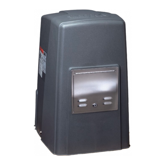
Model 9024
Model 9024
Model 9024
Vehicular Slide Gate Operator
Copyright 2009 DoorKing, Inc. All rights reserved.
9024-065-G-11-14
Optional Solar Power
Advertisement
Table of Contents
Troubleshooting

Related Manuals for DKS 9024


Summary of Contents for DKS 9024
- Page 1 Model 9024 Model 9024 Model 9024 Installation/Owner’s Manual Vehicular Slide Gate Operator Use this manual for circuit board 4100-010 Revision D or higher. 9024-065-G-11-14 Optional Solar Power Date Installed: Installer/Company Name: Circuit Board Serial Number Phone Number: and Revision Letter: Leave Manual with Owner Copyright 2014 DoorKing, Inc.
-
Page 3: Specifications
SPECIFICATIONS Use this manual for the Model 9024 operator with circuit board 4100-010 Rev D or higher ONLY. Class of Operation UL 325 Class I, II, III, IV Type of Gate Vehicular Slide Gates Only Drive Sprocket Size #40 Chain... -
Page 4: Table Of Contents
2.2 Setting Input Power Jumper and Turning Power ON 2.3 Solar Power Limitations SECTION 3 - AC POWER TO OPERATOR(S) 3.1 AC Power Wire Runs and Terminal Connection 3.2 Setting Input Power Jumper and Turning Power ON 3.3 Bi-Parting Gates - Dual Gate Operators 9024-065-G-11-14... - Page 5 Hard Shutdown 7.3 Manual Gate Operation SECTION 8 - MAINTENANCE AND TROUBLESHOOTING 8.1 Maintenance 8.2 Built-In Diagnostics 8.3 Troubleshooting 40-41 8.4 Accessory Items Model 9024-080 AC Input Power ONLY Wiring Diagram Model 9024-081 Solar Input Power ONLY Wiring Diagram 9024-065-G-11-14...
-
Page 6: Slide Gate Requirements
2 1/4 inches or less. non-compliant A contact sensor should be gate AND installed in this area for non-compliant adjacent fence safety. (See on next page that covers and page 30). open gate position (See above). Gate Frame and Adjacent Fence Area 9024-065-G-11-14... -
Page 7: Safety Information For Slide Gate Operators
Do not let children operate the gate or play in the gate area. This entrance is for vehicles only. Pedestrians must use separate entrance. Physical Stop Separate Pedestrian Walkway Located so pedestrians cannot come in contact with the vehicular gate. 9024-065-G-11-14... -
Page 8: Astm 2200 Standard For Gate Construction
2. Care shall be exercised to reduce the risk of nuisance tripping, such as when a vehicle trips the sensor while the gate is still moving in the opening direction. 3. One or more non-contact sensors shall be located where the risk of entrapment or obstruction exist, such as the perimeter reachable by a moving gate or barrier. 9024-065-G-11-14... -
Page 9: Important Notices
Do not allow children to play in the area of the operator or to play with any gate-operating device. • To remove the gate operator from service, operate the gate to the full open position and then shut off power to the operator at the service panel. 9024-065-G-11-14... -
Page 10: Ul325 Entrapment Protection
C - Inherent adjustable clutch or pressure relief device. D - Provision for connection of, or supplied with, an actuating device requiring continuous pressure to maintain opening or closing motion of the gate. E - An inherent audio alarm. 9024-065-G-11-14... -
Page 11: Glossary
ENTRAPMENT - The condition when an object is caught or held in a position that increases the risk of injury. 9024-065-G-11-14... -
Page 12: Section 1 - Installation
Sweep • DoorKing recommends using 3/4-inch conduit. Elbow • Be sure that all conduits are installed in accordance with local codes. • Never run low voltage rated wire insulation in the same conduit as high voltage rated wire insulation. 9024-065-G-11-14... -
Page 13: Gate Types
1.3 Typical Gate Types The Model 9024 operator is designed to be installed on any of these gate types. See the next 3 pages for specific operator mounting positions. • Steel or Aluminum. • 1,000 lb max. weight per gate. -
Page 14: Operator Mounting Positions
1.4 Operator Mounting Positions The Model 9024 operator is designed to be installed in the front, rear and center mounting positions shown on this page and the next 2 pages. V-wheel V-rail ornamental gates are shown as examples but other gate types on the previous page can use the same mounting setups. - Page 15 Additional hardware required. Post mount kit (P/N 9000-015). Endless idler assembly (P/N 2600-818) and additional chain #40 (P/N 2600-442 - 20 ft. per box) may be needed. 9024-065-G-11-14...
- Page 16 I d l e See page 17 for more information about endless idlers. DoorKing’s Chain Tray Kit for Long Gates See page 18 for more information. Gate shown in open position. Gate End Retainer Chain Tray 9024-065-G-11-14...
-
Page 17: Concrete Pad Setup Or Optional Post Mount Kit
Side View Optional Post Mount Kit Base Plate DoorKing offers a post mount kit specifically for the Model 9024 (P/N 9000-015). The kit Wall includes a base plate, 2 posts and hardware to Operator attach the operator to the base plate. This kit 4”... -
Page 18: Positioning Operator And Chain
Adjust the chain nuts to to Post Mount Plate tighten the chain. The chain should sag no Washers Use bolts provided in post more than one (1) inch per 10 feet of travel. mount kit. Do not over tighten the chain. 9024-065-G-11-14... -
Page 19: Endless Idler Assembly ( On Select Installations )
On Select Installations DoorKing offers an endless idler assembly with a protective cover designed for the Model 9024 installations (P/N 2600-818). Make sure the endless idler assembly is securely fastened to the wall or post (Depending on which type of installation will be used). -
Page 20: Doorking's Chain Tray Kit
Permanently install the supplied warning signs in locations so that the signs are visible by persons on both sides of the gate. • Use appropriate hardware such as wood or sheet metal screws (not supplied) to install the warning signs. 9024-065-G-11-14... -
Page 21: Concerns Before Solar Panel Installation
SOLAR POWER ONLY! MODEL 9024-081 1.11 Concerns BEFORE Solar Panel Installation Correct positioning of the solar panel will determine the efficiency of the system. In general, the panel should be facing TRUE SOUTH at a specific TILT ANGLE towards the sun using the information provided on the next page to achieve the highest efficiency. -
Page 22: Solar Panel Positioning
SOLAR POWER ONLY! MODEL 9024-081 1.12 Solar Panel Positioning These charts should be used only for estimates. Solar systems can vary from this information. These maps do not take into account small climate changes and may not be 100% accurate for all locations. -
Page 23: Section 2 - Solar Power To Operator(S)
2.1 Solar Power Connections Connect 24 VDC power to Model # 9024-081 ONLY. DoorKing Solar Power Kit P/N XXXX-XXX can be used. Third party 24 VDC batteries and solar panel can be used if desired. ONLY 24 VDC can be used with Model # 9024-081 operator. -
Page 24: Setting Input Power Jumper And Turning Power On
SECTION 2 - SOLAR POWER ONLY! MODEL 9024-081 2.2 Setting Input Power Jumper and Turning Power ON There is a “IN POWER/BATT” jumper on the circuit board that MUST be set correctly or the operator could get damaged. DO NOT cycle the operator until the “DIP-Switches”... -
Page 25: Section 3 - Ac Power To Operator(S)
SECTION 3 - AC INPUT POWER ONLY! MODEL 9024-080 Before attempting to connect any wiring to the operator, be sure that the circuit breaker in the electrical panel is in the OFF position. Permanent wiring must be installed to the operator as required by local electrical codes. It is recommended that a licensed electrical contractor perform this work. -
Page 26: Setting Input Power Jumper And Turning Power On
SECTION 3 - AC INPUT POWER ONLY! MODEL 9024-080 3.2 Setting Input Power Jumper and Turning Power ON There is a “IN POWER/BATT” jumper on the circuit board that MUST be set correctly or the operator could get damaged. DO NOT cycle the operator until the “DIP-Switches”... -
Page 27: Section 4 - Adjustments
Battery Plug P2 Terminal by placing the relay shorting bar on the N.O. 20-Pin or N.C. pins respectively. SW 1, switches 6 Main Terminal and 7 must be set to control relay. See next See pages 34 and 35. page for descriptions. 9024-065-G-11-14... -
Page 28: Dip-Switch Settings For 4100 Circuit Board
Normal Setting. Main terminal 10 is a REVERSE input. Reverse/Shadow Input Main terminal 10 is a SHADOW loop and is NOT used on the 9024. Single gate setting or overlapping gates are NOT used. Gates open at same time. Overlapping Overlapping gates ARE used (Dual gates ONLY). - Page 29 ONLY battery power (OFF) until batteries are drained. Then gate operator will fully open gate and shut down. MUST be turned OFF for the Model 9024. Terminal #10 is a reverse input. Do not turn ON. Switch 4 Switch 5 When the gate overlap is OFF, the gate operator(s) will start the open and close cycles at the same time.
-
Page 30: Limit Switches
Side View of Partial Open Assembly Magnet MUST align with partial open sensor. Adjustment Partial Open Sensor Lock-Plate Loosen adjustment nut Magnet to position the partial Clip open assembly to stop the opening gate at a desired “Partial Open” position. “Open” Limit Nut 9024-065-G-11-14... -
Page 31: Inherent Reverse Sensor Adjustment
Dual Operators: Each gate operator’s reverse sensor will have to be adjusted when dual operators have been installed. Model 9024-080 ONLY. Test the operator reversing sensitivity: Place an immobile object along the gate path, allowing the gate to strike it while in the open and close cycles. The gate must reverse direction after striking the object. -
Page 32: Section 5 - Entrapment And Safety Protection
Secondary Entrapment Protection Devices: In addition to the inherent reversing sensor system, the Model 9024 has a UL 325 terminal for the connection of photo sensors-Type B1 and reversing edges-Type B2 secondary entrapment protection devices required by UL 325 standards. Entrapment protection devices must be installed to reduce the risk of injury. -
Page 33: Secondary Entrapment Protection Device Locations
SW 1, switch 4 MUST be OFF. Photo Sensor Power Note: Photo sensors can be powered by the built-in convenience outlets (model 9024-080 ONLY) located on the operator (See previous page). 9024-065-G-11-14... - Page 34 Photo Sensor and Wireless Reverse Edge Sample Setup Photo Sensor Power Note: Photo sensors can be Closing- powered by the built-in convenience outlets (model Direction 9024-080 ONLY) located on the operator (See page 30). Install Opening-Direction Reversing reverse edges on the gate Edge support post(s) in this area.
-
Page 35: Loop Detectors
Note: Loop detector wiring is shown for LOOP DoorKing plug-in loop detector (P/N 9410-010 Single Channel). If third party loop detectors are used, refer to the installation instructions supplied with those detectors for wiring and Single Channel Loop separate power instructions. 9024-065-G-11-14... -
Page 36: Section 6 - Main Terminal Wiring
Connects to a DoorKing Tracker Expansion Board. Data will be reported about this gate operator’s SPECIFIC activity to a DoorKing 19 20 access control system. A list of the events will be “Tracked” and stored in the access control system. 9024-065-G-11-14... -
Page 37: Control Wiring
1837 or 1838) tracker system can be connected. The tracker board MUST 1 2 3 4 5 6 7 8 9 10 use a separate power source ONLY when using the model 9024-081 solar powered operator (DO NOT connected terminal #3 to the tracker board). -
Page 38: Section 7 - Operating Instructions
- Powers the AC ON (toggle up) or AC Power Switch OFF (toggle down). Not available on Model 9024-081. DC Power Switch - Powers the DC ON (toggle left) or OFF (toggle right). Note: If powering up operator using ONLY DC power,... -
Page 39: Shutdown Conditions
Activating this button will return the gate operator to normal operation, but will not cycle the gate operator. A remote alarm/reset station (P/N 1404-080) can be mounted external of the gate operator provided that it is installed in the line-of-sight of the gate and gate operator. 9024-065-G-11-14... -
Page 40: Manual Gate Operation
Pull Manual Release Handle Pull straight OUT as far as possible and then UP. Release Handle With handle in UP position, slide back down to lock it in manual release position. Manually Push Gate to Desired Position 9024-065-G-11-14... -
Page 41: Section 8 - Maintenance And Troubleshooting
Check that the black current sensor wire has been passed through the hole in the primary current sensor donut on the circuit board with the correct number of loops (1/2 HP motor - 2 loops, 1 HP motor - 1 loop). 9024-065-G-11-14... -
Page 42: Troubleshooting
If the motor does not run, or runs in only one direction, problem can be a bad motor, wire connections from the control board to the motor or a bad control board. If the motor runs in both steps above, contunue troubleshooting control board and accessories. 9024-065-G-11-14... - Page 43 Check that the operator is running in the proper direction (see “gate closes but will not open” above). Alarm sounds for 5 • Operator is in a “hard shutdown” condition. Reset button must be pressed to return operator to minutes and then normal operation. chirps once every 5 seconds. Operator will not run. 9024-065-G-11-14...
-
Page 44: Accessory Items
8.4 Accessory Items The following accessory items are available for the model 9024 slide gate operator. Contact Sensors - For use as a secondary entrapment protection device. Miller Edge, Inc., MGO20, MGR20, MGS20 Photo Cell - Non-contact (photocell) sensors for use as a secondary entrapment protection device. -
Page 45: Model 9024-080 Ac Input Power Only Wiring Diagram
Model 9024-080 AC Input Power ONLY Remote Radio Receiver Terminal Limit Switch Partial Limit Switch White Open 1 2 3 6 7 8 9 2 3 4 5 6 7 8 9 10 Sensor Brown Orange Yellow SELF TEST Orange... -
Page 46: Model 9024-081 Solar Input Power Only Wiring Diagram
Model 9024-081 Solar Input Power ONLY Remote Radio Receiver Terminal Limit Switch Partial Limit Switch White Open 1 2 3 6 7 8 9 2 3 4 5 6 7 8 9 10 Sensor Brown Orange Yellow SELF TEST Orange... - Page 47 9024-065-G-11-14...
-
Page 48: 9024-065
Model 9024 Model 9024 Model 9024 Installation/Owner’s Manual Vehicular Slide Gate Operator Use this manual for circuit board 4405-010 Revision D or higher. 9024-065-G-11-14 Optional Solar Power www.doorking.com DoorKing, Inc. 120 S. Glasgow Avenue Inglewood, California 90301 U.S.A. Phone: 310-645-0023 Fax: 310-641-1586 Copyright 2009 DoorKing, Inc.
Need help?
Do you have a question about the 9024 and is the answer not in the manual?
Questions and answers