Table of Contents
Advertisement
Quick Links
Download this manual
See also:
Owner's Manual
Installation/Owner's Manual
Use this manual for circuit board 4404-010 Revision A or higher.
Date Installed:
Installer/Company Name:
Phone Number:
Leave Manual with Owner
UL 325 Compliant
Heavy-Duty Vehicular Slide Gate Operator
C O
N F
A N
O R
M S
S I/
U L
T O
-3 2
C A
C E
5
W A
N /C
R T
S A
IF IE
V E
C 2
D
T O
H IC
2 .2
R N
N O
U L
C L
A R
. 2
53
A S
4 7
38
2
I N
S
G A
T E
G
M O
O P
D E
L
E R
A T
S E
O R
R IA
H P
L
V O
LT
S
A M
P S
M O
M A
X G
P H
S E
V IN
A S
A T
E
R IO
G
E L
G A
O A
U S
D o
D
6 0
O pe
T E
o rK
H z
IN
in g
an
ra te
J U
C A
d fr
ga
N
, In
ee
te
R Y
C A
c. ,
on
In g
D o
of
pe
ly
O R
U S
no
op
w he
le w
or
t al
le
n ga
D E
E
o o
op
lo w
an
A T
d ,
er at
d ob
te
C A
e ga
ch
ar ea
H
D o
ild
st ru
no
te .
re n
ct io
is
pa
t st
to
ns
in
si gh
th
an
pl ay
.
w hi
d in
t
le
in
R ea
ga
ga
ga
d ow
te
te
te
is
pa
th
ar ea
ne
m ov
or
r' s
in g.
w al
m an
k th
ua
l an
ro
ug
d sa
h
fe ty
in st
ru
ct io
ns
.
Circuit Board
Serial Number
and Revision Letter:
Copyright 2011 DoorKing, Inc. All rights reserved.
Series 9200
Series 9200
Series 9200
9210-065-B-9-11
Copyright 2009 DoorKing, Inc. All rights reserved.
TM
Advertisement
Table of Contents
Troubleshooting

Related Manuals for DKS 9200 Series


Summary of Contents for DKS 9200 Series
- Page 1 Installation/Owner’s Manual Series 9200 Series 9200 Series 9200 Heavy-Duty Vehicular Slide Gate Operator Use this manual for circuit board 4404-010 Revision A or higher. 9210-065-B-9-11 S I/ -3 2 N /C IF IE H IC 2 .2 R IA V IN R IO O pe o rK...
-
Page 3: Specifications
SPECIFICATIONS Use this manual for the 9200 series operators with circuit board 4404-010 Rev A or higher ONLY. Horse Mech. Disc Gate Slow Max Gate Electronic Pedestal Volt/Phase Amps Gearbox Chain # Power Brake Speed Down Weight - lbs. Module... -
Page 4: Table Of Contents
TABLE OF CONTENTS SPECIFICATIONS Gate Construction Important Safety Instructions Instructions regarding intended installation: Important Notices UL325 Entrapment Protection Glossary Slide Gate Requirements Slide Gate Protection SECTION 1 - INSTALLATION 1.1 Gate Hardware 1.2 Underground Conduit Requirements 1.3 Installation Options, Gate Types 11-12 1.4 Installation #1 1.5 Installation #2, Chain Tray Kit... - Page 5 TABLE OF CONTENTS 3.4 Inherent Reverse Sensor Adjustment 3.5 Current Sensor Adjustment 3.6 AC Module Adjustment SECTION 4 - ENTRAPMENT AND SAFETY PROTECTION 4.1 UL 325 Terminal Description 4.2 Secondary Entrapment Protection Device Locations 26-27 4.3 Loop Detector Wiring SECTION 5 - MAIN TERMINAL WIRING 5.1 Main Terminal Description 5.2 Control Wiring for Single/Primary Operator 5.3 Auxiliary Device Wiring...
-
Page 6: Gate Construction
ASTM F2200 Standard for Gate Construction Vehicular gates should be constructed and installed in accordance with ASTM F2200; Standard Specification for Automated Vehicular Gate Construction. For a copy of this standard, contact ASTM directly at 610-832-9585; service@astm.org; or www.astm.org. Important Safety Instructions WARNING - To reduce the risk of injury or death: 1. -
Page 7: Important Notices
• For gate operators utilizing contact sensors: 1. One or more contact sensors shall be located where the risk of entrapment or obstruction exist, such as at the leading edge, trailing edge, and post mounted both inside and outside of a vehicular horizontal slide gate. 2. -
Page 8: Ul325 Entrapment Protection
UL325 Entrapment Protection Class I Class II A vehicular gate operator (or system) intended for use in a A vehicular gate operator (or system) intended for use in a home of one-to four single family dwelling, or a garage or commercial location or building such as a multi-family parking area associated therewith. -
Page 9: Glossary
Glossary GATE - A moving barrier such as a swinging, sliding, raising, lowering, or the like, barrier, that is a stand-alone passage barrier or is that portion of a wall or fence system that controls entrance and/or egress by persons or vehicles and completes the perimeter of a defined area. -
Page 10: Slide Gate Requirements
Slide Gate Requirements The operator is intended for installation only on gates used for vehicles. Pedestrians must be supplied with a separate access opening. The pedestrian access opening shall be designed to promote pedestrian usage. Locate the gate such that persons will not come in contact with the vehicular gate during the entire path of travel of the vehicular gate. -
Page 11: Slide Gate Protection
Slide Gate Protection Entrapment protection devices are required to reduce the risk of injury. Install sensors where the risk of entrapment or obstruction exists while gate is moving. Individual requirements will vary. Contact Sensor (Reversing Edges) Warning Signs Installed on the fence to help minimize the potential of Permanently mounted entrapment between the gate and fence. -
Page 12: Section 1 - Installation
SECTION 1 - INSTALLATION Prior to beginning the installation of the slide gate operator, we suggest that you become familiar with the instructions, illustrations, and wiring guide-lines in this manual. This will help insure that your installation is performed in an efficient and professional manner compliant with UL 325 safety and ASTM F2200 construction standards. -
Page 13: Installation Options, Gate Types
1.3 Installation Options The operator MUST be level. See the next page for typical gate types. We suggest that you contact the local building depart- ment to determine the required depth of the concrete pad since soil conditions and code requirements vary from city to city. #1 - Operator Mounted Directly on a Concrete Pad Typically used when gates are less than 20 feet in length and under 2000 lbs. -
Page 14: Gate Types
1.3 Continued Gate Types v e r o v e t i l e g a t • Steel or Aluminum. n d e • 8,000 lb Max. Weight n t a per Gate (9240). r e c r a y r n a i n t c h a... -
Page 15: Installation #1
The operator is heavy. Two persons are required 1.4 Installation #1 when handling the operator during installation. Operator Mounted Directly on a Concrete Pad Tip: Trace the base plate of the operator on a piece of masonite (Not provided) and make a SI /U L- 32 IF IE... -
Page 16: Installation #2, Chain Tray Kit
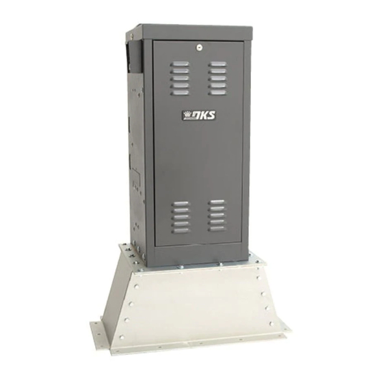
1.5 Installation #2 Operator Mounted on the Heavy-Duty Pedestal Mounting Stand The operator is heavy. Two persons are required when handling the operator during installation. Caution: DO NOT lay the operator on it’s side or oil will leak out of the gear reducer. 1. - Page 17 1.5 Continued - Chain Tray Kit Installing the Chain Tray Kit A chain tray is recommended for gates longer than 20 ft. to support the weight of the chain. DoorKing offers a chain tray kit in sections to fit any length gate. (DoorKing P/N 2601-270 10 Ft. section) Chain Tray Supporting Bracket...
-
Page 18: Chain Installation
Note: Be sure to follow all 3 guidelines. Installing the chain in any 1.6 Chain Installation other manner will cause excessive noise, chain idler wheel wear and chain stretching. Operator MUST be parallel to gate! Chain brackets MUST align with Chain brackets MUST be mounted idler wheels so chain stays parallel so the chain remains the same... -
Page 19: Installation Of Warning Signs
1.7 Installation of Warning Signs This DoorKing Slide Gate Operator is shipped with two warning signs. The purpose of the warning sign is to alert uninformed persons, and to remind persons familiar with the gate system, that a possible hazard exists so that appropriate action can be taken to avoid the hazard or to reduce exposure to the hazard. -
Page 20: High Voltage Terminal Connection
2.2 High Voltage Terminal Connection • Route incoming AC power wire through the high voltage conduit and run wire in the operator electronic box as shown. • Be sure wiring is installed in accordance with local codes. Be sure to color code all wiring. •... -
Page 21: Section 3 - Adjustments
SECTION 3 - ADJUSTMENTS The switch settings and adjustments in this chapter should be made after your installation and wiring to the operator(s) is complete. Whenever any of the programming switches on the circuit board are changed, power must be shut-off, and then turned back on for the new setting to take effect. -
Page 22: Dip-Switch Sw 1 And Sw 2 Settings
3.2 DIP-Switch SW 1 and SW 2 Settings The two DIP-switches located on the circuit board are used to program the operator to operate in various modes and to turn on or off various operating features. Whenever a switch setting is changed, power to the operator must be turned OFF and then turned back on for the new setting to take affect. - Page 23 3.2 Continued The two DIP-switches located on the circuit board (Upside-Down ) are used to program the operator to operate in various modes and to turn on or off various operating features. Whenever a switch setting is changed, power to the operator must be turned OFF and then turned back on for the new setting to take affect.
-
Page 24: Limit Switches
Check the polarity of “Three Phase” operator ONLY: Position the gate half 3.3 Limit Switches way open. Give open command and while gate is opening, activate the appropriate limit switch with your finger. Gate should STOP. If it does not, activate the other limit switch. -
Page 25: Inherent Reverse Sensor Adjustment
3.4 Inherent Reverse Sensors Adjustment This vehicular gate operator is equipped with an inherent adjustable reversing sensor (Type A) used as the primary entrapment protection system according to UL 325 standards. The gate will reverse direction after “physically” encountering an obstruction in either the opening or closing gate cycle. -
Page 26: Ac Module Adjustment
3.6 AC Module Adjustment The 9220, 9230 and 9240 models are equipped with an AC module that allows you to adjust the speed of the gate from 0 to 2 feet per second. To adjust the speed, simply rotate the speed control knob clockwise to increase the gate speed, or counter- clockwise to decrease the gate speed. -
Page 27: Section 4 - Entrapment And Safety Protection
Secondary Entrapment Protection Devices: In addition to the inherent reversing sensor system, the 9200 Series has a 6-pin UL 325 terminal for the connection of photo sensors-Type B1 and reversing edges-Type B2 secondary entrapment protection devices required by UL 325 standards. Entrapment protection devices must be installed to reduce the risk of injury. -
Page 28: Secondary Entrapment Protection Device Locations
4.2 Secondary Entrapment Protection Device Locations Typical UL Photo Sensor mounting height If the distance between the gate and distance away from gate. and wall is greater than 2 1/4”. Filler Post or Barrier Secure Side Non-Secure Side Inside Property Outside Property Reversing Edge (Open Contact Sensor) 5”... - Page 29 Wireless Reverse Edge Sample Setup - Single Receiver Edge Normally Open 9 V battery operated transmitter mounted on gate. Transmitter Filler Post Note: Install reversing edges on all Normally Open the gate support posts or filler post in this area (e.g.
-
Page 30: Loop Detector Wiring
4.3 Loop Detector Wiring To help protect the operator from accidentally closing on vehicles in the gate’s path, DoorKing highly recommends that loops and loop detectors be installed. Loops are laid underneath, cut into asphalt or concrete driveways or buried beneath gravel and earth driveways. -
Page 31: Section 5 - Main Terminal Wiring
SECTION 5 - MAIN TERMINAL WIRING 5.1 Main Terminal Description Auxiliary Common 4404 Terminal Connect any low voltage common wire to these 2 terminals. #2 - Jumper Wire - SW 1, switch 3 OFF (Dual Operators Full Open) #1 - Jumper Wire - SW 1, switch 3 OFF (Single Operator Exit Loop Partial Open) 19 19 18 18 17 16 15 14 13 12 11 10 9 8 7 6 5 4 3 2 1... -
Page 32: Control Wiring For Single/Primary Operator
5.2 Control Wiring for Single/Primary Operator Important: Controls must be far enough from the gate so that the user is prevented from coming in contact with the gate while operating the controls. Outdoor or easily accessible controls should have a security feature to prevent unauthorized use. Auxiliary Common Terminal 4404-010... -
Page 33: Auxiliary Device Wiring
5.3 Auxiliary Device Wiring 4404-010 20 19 18 17 16 15 14 13 12 11 10 9 8 3 2 1 Jumper Blue Alarm Reset Terminal Red Alarm Output Terminal White Common Terminal Remote Alarm Reset Station (DoorKing P/N 1404-080 Only) MUST be mounted in the line-of-sight of the gate operator. -
Page 34: Bi-Parting Gates Wiring - Dual Gate Operators
5.4 Bi-Parting Gates Wiring - Dual Gate Operators • Requires AC power to each operator. 1 2 3 UL 325 UL 325 UL 325 UL 325 4404-010 Terminal Terminal Terminal Terminal • Both operator DIP-switches must be set. • Connect all control devices, auxiliary Primary Operator devices and loops to the primary 20 19 18 17 16 15 14 13 12 11 10 9 8... -
Page 35: Section 6 - Operating Instructions
SECTION 6 - OPERATING INSTRUCTIONS IMPORTANT SAFETY INSTRUCTIONS WARNING - To reduce the risk of injury or death: 1. READ AND FOLLOW ALL INSTRUCTIONS. 2. Never let children operate or play with gate controls. Keep the remote control away from children. 3. -
Page 36: Shutdown Conditions
6.2 Shutdown Conditions Under various entrapment conditions the operator will assume either a soft or hard (alarm) shutdown. To determine what type of reset action is required, you will need to understand how the different entrapment conditions affect the gate operator. Soft Shutdown This occurs in various situations where the inherent or secondary entrapment protection devices have been activated. -
Page 37: Manual Gate Operation
6.3 Manual Gate Operation Caution: Never attempt to manually operate any gate until you have verified that power to the operator has been shut-off. Manual Crank Insert the supplied manual hand crank into the access hole until it engages with the motor shaft. Turn the crank to open the gate. -
Page 38: Section 7 - Maintenance And Troubleshooting
SECTION 7 - MAINTENANCE AND TROUBLESHOOTING Inspection and service of this gate operator by a qualified technician should be performed anytime a malfunction is observed or suspected. High cycle usage may require more frequent service checks. 7.1 Maintenance When servicing the gate operator, always check any secondary (external) reversing devices (loops, photocells, etc.) for proper operation. -
Page 39: Built-In Diagnostic Tests
7.2 Built-In Diagnostic Tests This gate operator is designed with built-in diagnostics that will alert you to potential or existing problems that the microproces- sor has detected. Specific fault conditions are checked and the operator will signal that a fault exist through the built-in alarm. Constant alarm is heard when power is applied: This indicates that the limit switch wire harness is not connected to the circuit board. - Page 40 Symptom Possible Solution • Check that AC power to the operator is turned ON. • Transformer may be overheated. Turn power off and allow board to cool for several minutes then retest. Check Operator will not run. for low VAC power and low voltage shorts. Power LED is OFF.
-
Page 41: Accessory Items
Chain Tray Kit - 10 Ft. section. Sections connect together to fit any length gate. P/N 2601-270 Pedestal Mounting Stand - Heavy-duty pedestal mounting stand for the 9200 series operator. P/N 9200-135 Heater and Fan Kit - Recommended for cold weather climates. -
Page 42: 9210-065
Installation/Owner’s Manual Series 9200 Series 9200 Series 9200 Heavy-Duty Vehicular Slide Gate Operator Use this manual for circuit board 4404-010 Revision A or higher. 9210-065-B-9-11 www.doorking.com DoorKing, Inc. 120 Glasgow Avenue Inglewood, California 90301 U.S.A. Phone: 310-645-0023 Fax: 310-641-1586 Copyright 2009 DoorKing, Inc. All rights reserved.
Need help?
Do you have a question about the 9200 Series and is the answer not in the manual?
Questions and answers