Table of Contents
Advertisement
Quick Links
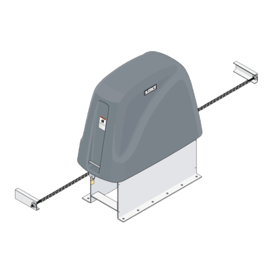
Installation/Owner's Manual
Maximum Security Heavy-Duty Vehicular Slide Gate Operator
Use this manual for circuit board 4404-010 Revision AA or higher.
EXTERNAL ENTRAPMENT PROTECTION MUST be
installed or the gate operator WILL NOT function.
THIS PRODUCT IS TO BE INSTALLED AND SERVICED BY A TRAINED GATE SYSTEMS TECHNICIAN ONLY.
Visit www.dkslocator.com to find a professional installing and servicing dealer in your area.
Date Installed:
Installer/Company Name:
Phone Number:
Leave Manual with Owner
UL 325 Compliant
Circuit Board
Serial Number
and Revision Letter:
Copyright 2016 DoorKing, Inc. All rights reserved.
Series 9500
Series 9500
Series 9500
9510-065-R-11-16
This vehicular gate operator is
designed for Class III and Class IV
applications ONLY and must
NEVER be used in applications
serving the general public.
Copyright 2009 DoorKing, Inc. All rights reserved.
Advertisement
Table of Contents
Troubleshooting

Related Manuals for DKS 9500 Series


Summary of Contents for DKS 9500 Series
- Page 1 Installation/Owner’s Manual Series 9500 Series 9500 Series 9500 Maximum Security Heavy-Duty Vehicular Slide Gate Operator Use this manual for circuit board 4404-010 Revision AA or higher. 9510-065-R-11-16 EXTERNAL ENTRAPMENT PROTECTION MUST be installed or the gate operator WILL NOT function. THIS PRODUCT IS TO BE INSTALLED AND SERVICED BY A TRAINED GATE SYSTEMS TECHNICIAN ONLY.
-
Page 2: Quick Guide: Dip-Switches
QUICK GUIDE: DIP-Switches See page 17 for more information about DIP-switches. The two DIP-switches located on the circuit board are used to program the operator to operate in various modes and to turn on or off various operating features. Whenever a switch setting is changed, power to the operator must be turned OFF and then turned back on for the new setting to take affect. -
Page 3: Quick Guide: Terminal Descriptions
QUICK GUIDE: Terminal Descriptions See page 26 for terminal wiring. 4404 Auxiliary Common Main Terminal Input LEDs Terminal #2 - Jumper Wire - SW 1, switch 3 OFF (Dual Operators Full Open) #1 - Jumper Wire - SW 1, switch 3 OFF (Single Operator Exit Loop Partial Open) 19 19 18 18 17 16 15 14 13 12 11 10 9 8 7 6 5 4 3 2 1... -
Page 4: Operator Specifications
OPERATOR SPECIFICATIONS Use this manual for the 9500 series operators with circuit board 4404-010 Rev AA or higher ONLY. Horse Mechanical Disc Gate Slow Max Gate Electronic Volt/Phase Amps Gearbox Chain # Power Brake Speed Down Weight - lbs. Module... -
Page 5: Table Of Contents
TABLE OF CONTENTS QUICK GUIDES Quick Guide: DIP-Switches Quick Guide-1 Quick Guide: Terminal Descriptions Quick Guide-2 Operator Specifications Previous Page Slide Gate Requirements Safety Information for Slide Gate Operators Gate Construction Important Safety Instructions Instructions regarding intended installation: Important Notices UL325 Entrapment Protection Glossary SECTION 1 - INSTALLATION... -
Page 6: Slide Gate Requirements
Slide Gate Requirements The operator is intended for installation only on gates used for vehicles. Pedestrians must be supplied with a separate access opening. The pedestrian access opening shall be designed to promote pedestrian usage. Locate the gate such that persons will not come in contact with the vehicular gate during the entire path of travel of the vehicular gate. -
Page 7: Safety Information For Slide Gate Operators
Illustration not to scale. Safety Information for Slide Gate Operators Physical Stops Entrapment protection devices are required to reduce the risk of injury. Positive stops shall be required Install sensors where the risk of entrapment or obstruction exists while to limit travel to the designed gate is moving. -
Page 8: Gate Construction
ASTM F2200 Standard for Gate Construction Vehicular gates should be constructed and installed in accordance with ASTM F2200; Standard Specification for Automated Vehicular Gate Construction. For a copy of this standard, contact ASTM directly at 610-832-9585; service@astm.org; or www.astm.org. Important Safety Instructions WARNING - To reduce the risk of injury or death: 1. -
Page 9: Important Notices
Important Notices Vehicular gate operator products provide convenience and security. However, gate operators must use high levels of force to move gates and most people underestimate the power of these systems and do not realize the potential hazards associated with an incorrectly designed or installed system. These hazards may include: •... -
Page 10: Ul325 Entrapment Protection
UL325 Entrapment Protection UL 325 Classifications Authoriz ed Personn el ONLY Class I - Residential Class III - Industrial/Limited Access Vehicular Gate Operator Vehicular Gate Operator A vehicular gate operator (or system) intended for use in garages A vehicular gate operator (or system) intended for use in an or parking areas associated with a residence of one-to four single industrial location or building such as a factory or loading dock families. -
Page 11: Glossary
Glossary GATE - A moving barrier such as a swinging, sliding, raising, lowering, or the like, barrier, that is a stand-alone passage barrier or is that portion of a wall or fence system that controls entrance and/or egress by persons or vehicles and completes the perimeter of a defined area. -
Page 12: Section 1 - Installation
SECTION 1 - INSTALLATION Prior to beginning the installation of the slide gate operator, we suggest that you become familiar with the instructions, illustrations, and wiring guide-lines in this manual. This will help insure that your installation is performed in an efficient and professional manner compliant with UL 325 safety and ASTM F2200 construction standards. -
Page 13: Concrete Pad Description, Gate Types
1.4 Concrete Pad Description Be sure the top of the concrete pad is level and a minimum of four (4) inches above ground level. See the next page for typical gate types. We suggest that you contact the local building department to determine the required depth of the pad since soil conditions and code requirements vary from city to city. - Page 14 Gate Types • Steel or aluminum. • 25,000 lb max. weight per gate (9575). • Chain tray recommended for gates v e r over 20 ft. t i l e • Single gate: 160 ft max. n t a • Dual gates: 320 ft max.
-
Page 15: Mounting Operator And Chain
1.5 Mounting Operator and Chain Positioning Operator and Chain Brackets Operator MUST be parallel to gate! Top View Chain brackets MUST align with idler wheels so chain stays parallel to gate! Chain Bracket Idler Wheels 4” minimum from operator chassis to gate. Note: Be sure to follow all 3 guidelines. -
Page 16: Installation Of Chain Tray
1.6 Installation of Chain Tray A chain tray is recommended for longer gates to support the weight of the chain. DoorKing offers a chain tray and supporting brackets in sections to fit any length gate. (DoorKing P/N 2601-270 10 Ft. section) View A WARNING MOVING GATE CAN CAUSE... -
Page 17: Section 2 - Ac Power To Operator(S)
SECTION 2 - AC POWER TO OPERATOR(S) Before attempting to connect any wiring to the operator, be sure that the circuit breaker in the electrical panel is in the OFF position. Permanent wiring must be installed to the operator as required by local electrical codes. It is recommended that a licensed electrical contractor perform this work. -
Page 18: High Voltage Terminal Connection
2.2 High Voltage Terminal Connection • Route incoming AC power wire through the high voltage conduit and run wire in the operator electronic box as shown. • Be sure wiring is installed in accordance with local codes. Be sure to color code all wiring. •... -
Page 19: Section 3 - Adjustments
SECTION 3 - ADJUSTMENTS The switch settings and adjustments in this chapter should be made after your installation and wiring to the operator(s) is complete. Whenever any of the programming switches on the circuit board are changed, power must be shut-off, and then turned back on for the new setting to take effect. -
Page 20: Dip-Switch Sw 1 And Sw 2 Settings
3.2 DIP-Switch SW 1 and SW 2 Settings The two DIP-switches located on the circuit board are used to program the operator to operate in various modes and to turn on or off various operating features. Whenever a switch setting is changed, power to the operator must be turned OFF and then turned back on for the new setting to take affect. - Page 21 3.2 Continued The two DIP-switches located on the circuit board (Upside-Down )are used to program the operator to operate in various modes and to turn on or off various operating features. Whenever a switch setting is changed, power to the operator must be turned OFF and then turned back on for the new setting to take affect.
-
Page 22: Limit Switches
Check the polarity: Position the gate half way open. Give open command 3.3 Limit Switches and while gate is opening, activate the appropriate limit switch with your finger. Gate should STOP. If it does not, activate the other limit switch. If this STOPS the gate, AC power wires must be changed (Reverse the connection of any 2 wires and re-check limits). -
Page 23: Inherent Reverse Sensor Adjustment
3.4 Inherent Reverse Sensors Adjustment This vehicular gate operator is equipped with an inherent adjustable reversing sensor (Type A) used as the primary entrapment protection system according to UL 325 standards. The gate will reverse direction after “physically” encountering an obstruction in either the opening or closing gate cycle. -
Page 24: Ac Module Adjustment
3.6 AC Module Adjustment 9500s are equipped with an AC module that allows you to adjust the speed of the gate from 0 to 2 ft/ sec or 0 to 4 ft/sec on the high speed models. To adjust the speed, simply rotate the speed control knob clockwise to increase the gate speed, or counter- clockwise to decrease the gate speed. -
Page 25: Section 4 - Entrapment And Safety Protection
SECTION 4 - ENTRAPMENT AND SAFETY PROTECTION External Entrapment Protection Devices: In addition to the inherent reversing sensor system, this operator has a UL 325 terminal for the connection of photo sensors-Type B1 and/or reversing edges-Type B2 entrapment protection required by UL 325 standards. External entrapment protection devices MUST be installed in BOTH directions of gate travel or the operator will NOT function. -
Page 26: Entrapment Protection Device Locations
4.2 Entrapment Protection Device Locations Typical UL Photo Sensor mounting height If the distance between the gate and distance away from gate. and wall is greater than 2 1/4”. Filler Post or Barrier 5” 5” Secure Side Non-Secure Side Inside Property Outside Property Reversing Edge (Open Contact Sensor) Less... - Page 27 Wireless Reverse Edge Sample Setup - Single Receiver Open Edge Edge transmitter mounted on gate. Open Beam Close Edge IMPORTANT: Photo sensors must Mount transmitter on gate. use Normally Closed (NC) contacts Edge with the beam set for light operate Transmitter (relay activated when beam is not obstructed).
-
Page 28: Loop Detector Wiring
4.3 Loop Detector Wiring To help protect the operator from accidentally closing on vehicles in the gate’s path, DoorKing highly recommends that loops and loop detectors be installed. Loops are laid underneath, cut into asphalt or concrete driveways or buried beneath gravel and earth driveways. -
Page 29: Section 5 - Main Terminal Wiring
SECTION 5 - MAIN TERMINAL WIRING 5.1 Main Terminal Description 4404 Auxiliary Common Main Terminal Input LEDs Terminal #2 - Jumper Wire - SW 1, switch 3 OFF (Dual Operators Full Open) #1 - Jumper Wire - SW 1, switch 3 OFF (Single Operator Exit Loop Partial Open) 19 19 18 18 17 16 15 14 13 12 11 10 9 8 7 6 5 4 3 2 1... -
Page 30: Control Wiring For Single/Primary Operator
5.2 Control Wiring for Single/Primary Operator Important: Controls intended for user activation must be located at least six (6) feet away from any moving part of the gate and where the user is prevented from reaching over, under, around or through the gate to operate the controls. Emergency access controls only accessible by authorized personnel (e.g., fire, police, EMS) may be placed at any location in the line-of-sight of the gate. -
Page 31: Auxiliary Device Wiring
5.3 Auxiliary Device Wiring 4404-010 20 19 18 17 16 15 14 12 11 10 9 Gate Tracker - DoorKing Access Control System (Model 1833, 1835, 1837 or 1838) tracker system can be connected. This system can keep track of gate operator cycle count, shorted inputs, loop detector problems, any forced entry attempts, if the gate has struck anything during the open or close cycle, power interruptions, etc. -
Page 32: Bi-Parting Gates Wiring - Dual Gate Operators
5.4 Bi-Parting Gates Wiring - Dual Gate Operators • Requires AC power to each operator. 1 2 3 3 2 1 UL 325 UL 325 UL 325 UL 325 UL 325 DIP-switches 1, 4404-010 Terminal Terminal Terminal Terminal 2 and 3 MUST be ON. •... -
Page 33: Section 6 - Operating Instructions
SECTION 6 - OPERATING INSTRUCTIONS IMPORTANT SAFETY INSTRUCTIONS This vehicular gate operator is designed for Class III and Class IV applications only. All users of this gate operating system MUST be trained on the proper and safe operation of the system and must made aware of all hazards that may be associated with the system. -
Page 34: Shutdown Conditions
6.2 Shutdown Conditions Under various entrapment conditions the operator will assume either a soft or hard (alarm) shutdown. To determine what type of reset action is required, you will need to understand how the different entrapment conditions affect the gate operator. Soft Shutdown This occurs in various situations where the inherent or external entrapment protection devices have been activated. -
Page 35: Manual Gate Operation
6.3 Manual Gate Operation Caution: Never attempt to manually operate any gate until you have verified that power to the operator has been shut-off. Manually Remove the Cover Crank - Cuts off AC Interlock power to the operator. Inside Cover Catch Padlock Bracket... -
Page 36: Section 7 - Maintenance And Troubleshooting
SECTION 7 - MAINTENANCE AND TROUBLESHOOTING Inspection and service of this gate operator by a qualified technician should be performed anytime a malfunction is observed or suspected. High cycle usage may require more frequent service checks. 7.1 Maintenance When servicing the gate operator, always check any secondary (external) reversing devices (loops, photocells, etc.) for proper operation. -
Page 37: Built-In Diagnostic Tests
7.2 Built-In Diagnostic Tests This gate operator is designed with built-in diagnostics that will alert you to potential or existing problems that the microproces- sor has detected. Specific fault conditions are checked and the operator will signal that a fault exist through the built-in alarm. Constant alarm is heard when power is applied: This indicates that the limit switch wire harness is not connected to the circuit board. - Page 38 Symptom Possible Solution • Check that AC power to the operator is turned ON. • Transformer may be overheated. Turn power off and allow board to cool for several minutes then retest. Check Operator will not run. for low VAC power and low voltage shorts. Power LED is OFF.
-
Page 39: Accessory Items
7.4 Accessory Items UL 325 Monitored Entrapment Protection Devices available for the series 9500 slide gate operators. Type B2 Contact Sensors (Reversing Edge) Miller Edge Sensing Edges - all models with a T2 (resistive) termination. Miller Edge Monitored Gate Link Model MGL-K20 Type B1 Non-contact Sensors (Photo Cell) Miller Edge Reflective-Guard Model RG Miller Edge Prime-Guard Model PG... - Page 40 Installation/Owner’s Manual Series 9500 Series 9500 Series 9500 Maximum Security Heavy-Duty Vehicular Slide Gate Operator Use this manual for circuit board 4404-010 Revision AA or higher. 9510-065-R-11-16 EXTERNAL ENTRAPMENT PROTECTION MUST be installed or the gate operator WILL NOT function. This vehicular gate operator is designed for Class III and Class IV applications ONLY and must NEVER be used in applications serving the general public.
Need help?
Do you have a question about the 9500 Series and is the answer not in the manual?
Questions and answers