Table of Contents
Advertisement
Quick Links
Installation/Owner's Manual
Use this manual for circuit board 4100-010 Revision D or higher.
Solar Powered
Date Installed:
Installer/Company Name:
Phone Number:
Leave Manual with Owner
UL 325 Compliant
Model 9024-081
Model 9024-081
Model 9024-081
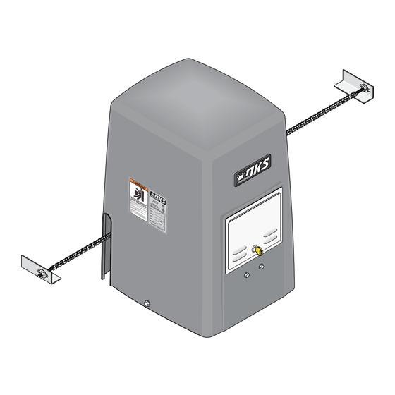
Solar Powered Vehicular Slide Gate Operator
Circuit Board
Serial Number
and Revision Letter:
Copyright 2015 DoorKing, Inc. All rights reserved.
9024-066-H-1-15
Solar Powered
Copyright 2009 DoorKing, Inc. All rights reserved.
Advertisement
Table of Contents
Troubleshooting

Subscribe to Our Youtube Channel
Related Manuals for DKS 9024-081


Summary of Contents for DKS 9024-081
- Page 1 Installation/Owner’s Manual Model 9024-081 Model 9024-081 Model 9024-081 Solar Powered Vehicular Slide Gate Operator Use this manual for circuit board 4100-010 Revision D or higher. 9024-066-H-1-15 Solar Powered Solar Powered Date Installed: Installer/Company Name: Circuit Board Serial Number Phone Number:...
-
Page 2: Quick Guide: Dip-Switches
QUICK GUIDE: DIP-Switches See page 24 for more information about DIP-switches. Reset button on circuit board MUST be pressed before new DIP-switch settings will take affect. SW 1 (Top 8 DIP Switches) Switch Function Setting Description Opening direction Opening direction Operator Changes direction operator will cycle open using ON setting. -
Page 3: Quick Guide: Terminal Descriptions
QUICK GUIDE: Terminal Descriptions See page 25 for terminal wiring. UL 325 Terminal Terminals 1, 2 and 3 are ALWAYS powered up. Even when circuit board has powered down to manage the UL 325 power drain on the batteries. See pages 27 - 29 ONLY connect opening devices to terminal 2. -
Page 4: Specifications For Model 9024-081
SPECIFICATIONS FOR MODEL 9024-081 Use this manual for the Model 9024-081 operator with circuit board 4100-010 Rev D or higher ONLY. Class of Operation UL 325 Class I, II, III, IV Type of Gate Vehicular Slide Gates Only Drive Sprocket Size... -
Page 5: Table Of Contents
SECTION 6 - OPERATING INSTRUCTIONS 6.1 Operator Controls and Resets 6.2 Shutdown Conditions 6.3 Manual Gate Operation SECTION 7 - MAINTENANCE AND TROUBLESHOOTING 7.1 Maintenance 7.2 Built-In Diagnostics 7.3 Troubleshooting 37-38 7.4 Accessory Items Model 9024-081 Solar Input Power Wiring Diagram 9024-066-A-1-15... -
Page 6: Slide Gate Requirements
Illustrations not to scale. Slide Gate Requirements The operator is intended for installation only on gates used for vehicles. Pedestrians must be supplied with a separate access opening. The pedestrian access opening shall be designed to promote pedestrian usage. Locate the gate such that persons will not come in contact with the vehicular gate during the entire path of travel of the vehicular gate. -
Page 7: Safety Information For Slide Gate Operators
Illustration not to scale. Safety Information for Slide Gate Operators Entrapment protection devices are required to reduce the risk of injury. Physical Stops Install sensors where the risk of entrapment or obstruction exists while Positive stops shall be required gate is moving. Individual requirements will vary. See pages 27-29 for to limit travel to the designed more information on typical layout locations and setup. -
Page 8: Astm 2200 Standard For Gate Construction
ASTM F2200 Standard for Gate Construction Vehicular gates should be constructed and installed in accordance with ASTM F2200; Standard Specification for Automated Vehicular Gate Construction. For a copy of this standard, contact ASTM directly at 610-832-9585; service@astm.org; or www.astm.org. Important Safety Instructions WARNING - To reduce the risk of injury or death: 1. -
Page 9: Important Notices
• For gate operators utilizing contact sensors: 1. One or more contact sensors shall be located where the risk of entrapment or obstruction exist, such as at the leading edge, trailing edge, and post mounted both inside and outside of a vehicular horizontal slide gate. 2. -
Page 10: Ul325 Entrapment Protection
UL 325 Entrapment Protection Class I Class II A vehicular gate operator (or system) intended for use in a A vehicular gate operator (or system) intended for use in a home of one-to four single family dwelling, or a garage or commercial location or building such as a multi-family parking area associated therewith. -
Page 11: Glossary
Glossary GATE - A moving barrier such as a swinging, sliding, raising, lowering, or the like, barrier, that is a stand-alone passage barrier or is that portion of a wall or fence system that controls entrance and/or egress by persons or vehicles and completes the perimeter of a defined area. -
Page 12: Section 1 - Installation
SECTION 1 - INSTALLATION Prior to beginning the installation of the slide gate operator, we suggest that you become familiar with the instructions, illustrations, and wiring guide-lines in this manual. This will help insure that your installation is performed in an efficient and professional manner compliant with UL 325 safety and ASTM F2200 construction standards. -
Page 13: Typical Gate Types
1.3 Typical Gate Types The Model 9024 operator is designed to be installed on any of these gate types. See pages 13-15 for specific operator mounting positions. • Steel or Aluminum. • 1,000 lb max. weight per gate. • Chain tray recommended for gates over 20 ft. (Post mount installation when using a chain tray.) •... -
Page 14: Concerns Before Solar Panel Installation
OPTIONAL DKS Solar Power Kit P/N xxxx-xxx. If other solar sources are used, output MUST be 24 VDC. 9024-066-A-1-15... -
Page 15: Solar Panel Positioning
1.5 Solar Panel Positioning These charts should be used only for estimates. Solar systems can vary from this information. These maps do not take into account small climate changes and may not be 100% accurate for all locations. Solar Panel MUST Point “TRUE SOUTH” It is important for proper system operation that the solar panel is oriented to TRUE SOUTH. -
Page 16: Operator Mounting Positions
1.6 Operator Mounting Positions The Model 9024 operator is designed to be installed in the front, rear and center mounting positions shown on this page and the next 2 pages. V-wheel V-rail ornamental gates are shown as examples but other gate types on the previous page can use the same mounting setups. - Page 17 Rear Position with Concrete Pad Idler Wheels and Chain Setup Hides the chain from outside the property looking in. • Set one chain Idler wheel at the top and one in the center position. A filler post or barrier may need to be installed between Top View the gate and wall area (See page 3 for more information).
- Page 18 Center Position with Post Mount Kit Hides the chain from outside the property looking in. Allows the use of DoorKing’s chain tray kit to attach to gate. This is useful with long gates. It supports the chain’s weight and helps prevent chain “stretching”. Idler Wheels and Chain Setup •...
-
Page 19: Concrete Pad Setup Or Optional Post Mount Kit
1.7 Concrete Pad Setup OR Post Mounting Concrete Pad Setup Gate 4” Minimum Side View 8” 13” Conduit Concrete pad Area MUST be level. Concrete Pad 3.75” 2” 2” 2” 2.5” 3.75” Center 4.5” 3.5” 12” 12” 4” min. above ground. Concrete Pad 24”... -
Page 20: Positioning Operator And Chain
1.8 Positioning Operator and Chain Operator and chain are NOT Operator and chain Chain Chain parallel to gate. Bracket MUST be parallel to gate! Idler Wheels Lines up with Idler Wheels Chain bracket MUST line up with chain idler wheels! Chain bracket does NOT align with... -
Page 21: Endless Idler Assembly (On Select Installations)
1.10 Endless Idler Assembly On Select Installations DoorKing offers an endless idler assembly with a protective cover designed for the Model 9024 installations (P/N 2600-818). Make sure the endless idler assembly is securely fastened to the wall or post (Depending on which type of installation will be used). -
Page 22: Doorking's Chain Tray Kit
1.11 DoorKing’s Chain Tray Kit A chain tray is recommended for gates longer than 20 ft. to support the weight of the chain. DoorKing offers a chain tray kit in 10 ft. sections to fit any length gate. (DoorKing P/N 2601-270 10 Ft. section) The Chain tray supporting brackets can be mounted facing up (as shown) Chain Tray... -
Page 23: Section 2 - Solar Input Power To Operator
CAUTION DO NOT connect an AC input power wire to the Model 9024-081’s power terminal DKS Solar Power Kit 12V 18 A/Hr batteries when using Solar Power or DAMAGE will fit in battery rack in operator. occur and VOID the warranty! -
Page 24: Power Select Jumper And Turning Power On
2.2 Power Select Jumper and Turning Power ON The “POWER SEL” jumper on the circuit board MUST be set correctly or operator will not function correctly. DO NOT To power up operator: turn DC power cycle the operator until the “DIP-Switches” and the “Limit Switches” switch ON. -
Page 25: Section 3 - Adjustments
SECTION 3 - ADJUSTMENTS The switch settings and adjustments in this chapter should be made after your installation and wiring to the operator(s) is complete. Whenever any of the programming DIP-switches on the circuit board are changed, reset button MUST be pressed before the new setting will take effect. -
Page 26: Dip-Switch Settings For 4100 Circuit Board
3.2 DIP-Switch Settings for 4100 Circuit Board The two DIP-switches located on the circuit board are used to program the operator to operate in various modes and to turn on or off various operating features. Whenever a switch setting is changed, reset button must be pressed for the new setting to take affect. - Page 27 3.2 DIP-Switches Continued SW-1 Switch (Top 8 switches on circuit board) Must OPEN the operator’s gate upon initial AC power up and Switch 1 - Operator Opening Direction: Typical Settings open command. If the first open command begins to close the gate, turn AC power off and reverse this SW 1 Opening - RT/LT switch.
-
Page 28: Limit Switches
3.3 Limit Switches Open and Close Limits MUST be Set The operator normally stops a cycling gate using the open and close limits. If the limits have not been set, the gate could continue beyond its full open and close positions, damaging the gate and operator. DO NOT allow this to occur! “Opening Direction”... -
Page 29: Inherent Reverse Sensor Adjustment
3.4 Inherent Reverse Sensor Adjustment This vehicular gate operator is equipped with an inherent adjustable reversing sensor (Type A) used as the primary entrapment protection system according to UL 325 standards. The gate will reverse direction after “physically” encountering an obstruction in either the opening or closing gate cycle. -
Page 30: Section 4 - Entrapment And Safety Protection
SECTION 4 - ENTRAPMENT AND SAFETY PROTECTION Secondary Entrapment Protection Devices: In addition to the inherent reversing sensor system, the Model 9024 has a UL 325 terminal for the connection of photo sensors-Type B1 and reversing edges-Type B2 secondary entrapment protection devices required by UL 325 standards. Entrapment protection devices must be installed to reduce the risk of injury. -
Page 31: Secondary Entrapment Protection Device Locations
4.2 Secondary Entrapment Protection Device Locations Typical UL Photo Sensor mounting height If the distance between the gate and distance away from gate. and wall is greater than 2 1/4”. Filler Post or Barrier Non-Secure Side Secure Side Outside Property Inside Property 5”... - Page 32 Wireless Reverse Edge Sample Setup - Single Receiver Edge Normally Open 9 V battery operated transmitter mounted on gate. Transmitter Filler Post Note: Install reversing edges on all Normally Open the gate support posts or filler post in this area (e.g.
-
Page 33: Loop Detectors
4.3 Loop Detector Wiring To help protect the operator from accidentally closing on vehicles in the gate’s path, DoorKing highly recommends that loops and loop detectors be installed. Loops are laid underneath, cut into asphalt or concrete driveways or buried beneath gravel and earth driveways. -
Page 34: Section 5 - Main Terminal Wiring
SECTION 5 - MAIN TERMINAL WIRING 5.1 Terminal Descriptions Terminals 1, 2 and 3 are ALWAYS powered up. Even when circuit board has powered down to manage the UL 325 Terminal power drain on the batteries. See pages 27 - 29 ONLY connect opening devices to terminal 2. -
Page 35: Control Wiring
5.2 Control Wiring UL 325 10-Pin Terminal 3-Wire Important: Radio Controls UL 325 intended for user activation Receiver See pages 27 - 29 must be located at least ten (10) feet away from any 3-Pin moving part of the gate and Remote e Gat Slid... -
Page 36: Section 6 - Operating Instructions
SECTION 6 - OPERATING INSTRUCTIONS IMPORTANT SAFETY INSTRUCTIONS WARNING - To reduce the risk of injury or death: 1. READ AND FOLLOW ALL INSTRUCTIONS. 2. Never let children operate or play with gate controls. Keep the remote control away from children. 3. -
Page 37: Shutdown Conditions
6.2 Shutdown Conditions Under various entrapment conditions the operator will assume either a soft or hard (alarm) shutdown. To determine what type of reset action is required, you will need to understand how the different entrapment conditions affect the gate operator. Soft Shutdown (NO Alarm will Sound) This occurs in various situations where the inherent or secondary entrapment protection devices have been activated. -
Page 38: Manual Gate Operation
6.3 Manual Gate Operation Caution: Never attempt to manually operate any gate until you have verified that power to operator has been shut-off. Pull Manual Release Handle Pull straight OUT as far as possible and then UP. Release Handle With handle in UP position, slide back down to lock it in manual release position. Manually Push Gate to Desired Position 9024-066-A-1-15... -
Page 39: Section 7 - Maintenance And Troubleshooting
SECTION 7 - MAINTENANCE AND TROUBLESHOOTING Inspection and service of this gate operator by a qualified technician should be performed anytime a malfunction is observed or suspected. High cycle usage may require more frequent service checks. 7.1 Maintenance When servicing the gate operator, always check any secondary (external) reversing devices (loops, photocells, etc.) for proper operation. If external reversing devices cannot be made operable, do not place this operator in service until the malfunction can be identified and corrected. -
Page 40: Troubleshooting
7.3 Troubleshooting Have a good VOM meter with Min/ Max test button to check voltages and continuity. A Meg-Ohm meter capable of checking up to 500 meg-ohms of resistance is necessary to properly check the integrity of the ground loops. When a malfunction occurs, isolate the problem to one of three areas: 1) the operator, 2) the loop system, 3) the keying devices. - Page 41 Symptom Possible Solution(s) Secondary operator • Check that SW-2, switch 3 is ON. motor will not run. • Check Motor: Gate must be half way open before testing motor. Turn AC power OFF and remove plug P2 from circuit board. On the P2 terminal, connect terminal 1 to terminal 5 and terminal 2 to terminal 6.
-
Page 42: Accessory Items
7.4 Accessory Items The following accessory items are available for the model 9024 slide gate operator. Contact Sensors - For use as a secondary entrapment protection device. Miller Edge, Inc., MGO20, MGR20, MGS20 Photo Cell - Non-contact (photocell) sensors for use as a secondary entrapment protection device. MMTC, Inc. -
Page 43: Model 9024-081 Solar Input Power Wiring Diagram
Model 9024-081 Solar Input Power ONLY Remote Radio Receiver Terminal Limit Switch Partial Open Limit Switch White Sensor 1 2 3 6 7 8 9 2 3 4 5 6 7 8 9 10 (Not Used) Brown Orange Yellow SELF TEST... -
Page 44: 9024-066
Installation/Owner’s Manual Model 9024-081 Model 9024-081 Model 9024-081 Solar Powered Vehicular Slide Gate Operator Use this manual for circuit board 4100-010 Revision D or higher. 9024-066-H-1-15 www.doorking.com DoorKing, Inc. 120 S. Glasgow Avenue Inglewood, California 90301 U.S.A. Phone: 310-645-0023 Fax: 310-641-1586...
Need help?
Do you have a question about the 9024-081 and is the answer not in the manual?
Questions and answers