Kemppi KM 300 Service Manual
Hide thumbs
Also See for KM 300:
- Operating manual (31 pages) ,
- Operating manual (20 pages) ,
- Operating manual (22 pages)

Related Manuals for Kemppi KM 300


Summary of Contents for Kemppi KM 300
-
Page 1: Service Manual
Service manual v. 1.0 FastMig KM 300 KMS 300 KM 400 KMS 400 KM 500 KMS 500 MF 29 MF 33 MSF 53 MSF 55 MSF 57... -
Page 2: Table Of Contents
Table of contents Technical data Fastmig KM / MF................3 FastMig KMS / MFS................ 4 Fastmig KMS / MVU................ 5 Main circuit diagram KM....................6-7 MF....................8 KMS....................9 MSF....................10 KM / MVU..................11 KMS / MVU..................12 Block diagram....................13 Main circuit card Z001 KM / KMS Operating diagram................ -
Page 3: Technical Data
Technical data FastMig KM / MF... -
Page 4: Fastmig Kms / Mfs
Technical data FastMig KMS / MSF... -
Page 5: Fastmig Kms / Mvu
Technical data FastMig KMS / MVU... -
Page 6: Main Circuit Diagram
Main circuit diagram L001 Z002 Z001 T001 Z003 Choke Capasitor card Main circuit Main transformer Secondary card card R001 S001 L001 RC001 Varistors Main switch Secondary choke RC-protection G003 Diode bridge T002 M001 A001 F001 H001 / 002 A002 P001 Aux. - Page 7 Main circuit diagram KM...
- Page 8 Main circuit diagram MF...
-
Page 9: Kms
Main circuit diagram KMS... -
Page 10: Msf
Main circuit diagram MSF... -
Page 11: Km / Mvu
Main circuit diagram KM / MVU... -
Page 12: Kms / Mvu
Main circuit diagram KMS / MVU... -
Page 13: Block Diagram
Block diagram Control card A001 Main circuit card Z001 •Microcontroller •PWM circuit •EMI filtering •Secondary voltage measurement •Three phase rectifier (V6) •Secondary current measurement •Switching-ON transient suppression •IGBT driver •Power Stage •Auxiliary device connection •Current transformer (T1) •Auxiliary power supply •Machine size jumpers (J1, J2) •Primary current limit jumpers... -
Page 14: Main Circuit Card Z001 Km / Kms
Main circuit card Z001 KM / KMS DC-link (+) IGBT gates From main switch Main transformer primary coil DC-link (-) Operating diagram - EMI filtering - Three phase rectifier (V6) - Switching-ON transient suppression - Power Stage - Current transformer (T1) -
Page 15: Operation Principle
Main circuit card Z001 Operation principle Approx.. + 570 V When IGBT-transistors G1 and G4 conduct, there is a positive voltage U in main transformer T1 primary and when IGBT-transistors G2 and G3 conduct there is a negative voltage U in main transformer primary. -
Page 16: Connectors
Main circuit card Z001 Connectors Z001 connectors / signals Z001 connectors / signals Primary choke Main switch Primary choke Main switch DC-link voltage (+) Main switch DC-link voltage (+) Chassis ground DC-link voltage (-) Chassis ground DC-link voltage (-) Main transformer Chassis ground Main transformer Current transformer secondary... -
Page 17: Operational Measurings
Main circuit card Z001 Operational measurings Main transformer T001 primary voltage, IGBT-gate pulses, set values 50 A/16,5 V set values 50 A/16,5 V... -
Page 18: Capacitor Card Z002
Capacitor card Z002 Operating diagram - Energy storage - Discharging Connectors Z002 connectors / signals DC + DC + DC - DC -... -
Page 19: Secondary Rectifier Card Z003
Secondary rectifier card Z003 Operating diagram Z003 X5-X8 X1-X4 - Rectifying - Snubber - Protection against HF Connectors Z003 connectors / signals Main transformer Main transformer Main transformer Main transformer Secondary choke Secondary choke Secondary choke Secondary choke Operational mesurings X003, machine (-) pole Z003 Voltage after secondary rectifier card Z003,... -
Page 20: Control Card A001
Control card A001 Operating diagram - Microcontroller - PWM circuit - Secondary voltage measurement - Secondary current measurement - IGBT driver - Auxiliary device connection - Auxiliary power supply - Machine size jumpers (J1, J2) - Primary current limit jumpers (J3, J4, J5) - Operational jumpers - LED’s - Water cooler connection... -
Page 21: Connectors
Control card A001 Connectors A001 / X1 A001 / X9 / KM X9/1 System bus DATA DC-link voltage (+) X9/2 System bus DATA B X9/3 A001 / X2 X9/4 + 50 V X2/1 20V auxiliary voltage~ X9/6 X2/2 20V auxiliary voltage ground X9/7 X2/3 20V auxiliary voltage~... -
Page 22: Operation Of The Leds On Control Card
Control card A001 Connectors A001 / X13 A001 / X16 X13/1 PTC, Rg 101 (Z001) X16/7 H002 + (yellow led) X13/2 PTC, Rg 101 (Z001) X16/8 H002 - X16/9 H001 + (green led) X16/10 H001 - A001 / X14 X14/1 PTC, Rt 101 (T001) A001 / X17 X14/2 PTC, Rt 101 (T001) X17/1 +24V... -
Page 23: Motor Control Card A002
Motor control card A002 Operating diagram - WF-motor control - Connection to the panel card P001 - Remote controller connection - MIG gun connection - Solenoid valve connection - Fuse - ID-Chip connection (MSF) -
Page 24: Connectors
Motor control card A002 (A001 = MSF) Connectors A002 / X1 / KM X1/1 Connection to A001, X9/4 X1/4 Connection to A001, X9/10 A001 / X1 / MSF X1/1 Bus +50V X1/3 Tacho +5V X1/4 Bus GND X1/5 Tacho GND X1/6 Tacho Signal A002/A001 / X2... -
Page 25: Id-Chip Card A002 (Msf)
ID chip card A002 (MSF) A002 ID-chip card Connectors A002 ID Bus 1 (connection to A001) ID Bus 2 (connection to A001) -
Page 26: Operating Diagram
Panel card P001 / KM Operating diagram - Main micro controller - User interface (buttons, potentiometers, displays, LED’s) - Connection to the A002 Connectors P001 / X2 Connection to A002... -
Page 27: Error Codes
Error codes Power source 1 ..50 MIG Logic 51 ….. 100 Curve Access 101 ….. 130 Robot Interface 131 ….. 150 MIG / TIG Unit 151 ….. 200 User interface 201 ….. 250 Others 0 ….. 999 Err 2: Power source undervoltage ( new start up ) Err 3: Power source overvoltage ( new start up ) -
Page 28: Setup Menu
Setup menu MF 29 / 33 FastMig Basic (MF) SETUP menu SF 51, 52, 53, 54 Normal MIG 1-MIG FR-MIG All MIG processes FastMig Synergic (MSF) setup menu... -
Page 29: Wire Feed Speed Calibration / Km
Wire feed speed calibration / KM • In factory set Wfs is adjusted in the range of 4...100 without any unit • LED light and feed roll symbol tells that the parameter to be set is Wfs • After Wfs Calibration m/min unit is displayed •... - Page 30 Wire feed speed calibration If wire feeding speed is not correct (too slow or too fast), motor control card A002 must be calibrated by following instruction: • Set ‘MIN’ and ‘MAX’ -trimmers to middle position. • Set ‘IR-comp’ -trimmer to clock vice maximum. •...
-
Page 31: Structure
Structure KM / KMS Mains connector varistors Z001 Main circuit board S001 Main switch Z002 DC-link R001 Capasitor board Shunt resistor P001 Panel card A002 (KM) Wire feed control card A001 Control card Water cooler Power connector... - Page 32 Structure KM / KMS T002 L001 Auxiliary Choke transformer L002 Secondary Z003 choke Secondary rectifier diodes Capacitors and varistors...
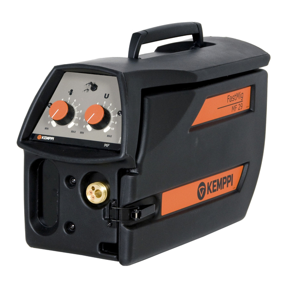
- Page 33 Structure MF 29 / 33 Dura Torque wire feeding mechanism Axle for wire reel coop Control cable connector & wiring Welding gun connection Solenoid valve Welding current connector Dura Torque wire feeding mechanism & copper bar...
-
Page 34: Mfs
Structure MSF 53 / 55 / 57 A001 Motor control card A002 ID-chip card... -
Page 35: Igbt Testing
IGBT testing C1/3 B1/4 X14/G3 X11/ X10/G4 C2E1/1 X12/G1 B2/6 X8/G2 E2/2 C1/3 B1/4 C2E1/1 B2/6 B1/4 E2/2... -
Page 36: Igbt Replacing
IGBT replacing Mounting the IGBT to the heat sink The tools and premises used in this work must be clean and free of dirt and dust. Even very small particles (0,050mm) between the surfaces may increase the gap between heatsink and module, causing overheating ans possible damage.
Need help?
Do you have a question about the KM 300 and is the answer not in the manual?
Questions and answers